Viale Vicenza, 14
36063 Marostica VI - Italy
www.vimar.com
49401655A0 01 2212
CARATTERISTICHE
• Tensione di alimentazione dal bus: da 9 a 15 V
• Corrente assorbita: 80 mA
• Temperatura di funzionamento: da -10 a +40 °C
• Grado di sicurezza: 3
• Classe ambientale: III
• Dimensioni (L x A x P): 140 x 150 x 20 mm
CONFORMITA' NORMATIVA.
Direttiva EMC. Direttiva RoHS.
Norme EN 50130-4, EN 50130-5, EN 55032, EN 50131-3, EN IEC 63000
Regolamento REACh (UE) n. 1907/2006 – art.33. Il prodotto potrebbe contenere tracce di
piombo.
RAEE - Informazione agli utilizzatori
Il simbolo del cassonetto barrato riportato sull’apparecchiatura o sulla sua confezione indica che il prodotto alla fine della
propria vita utile deve essere raccolto separatamente dagli altri rifiuti. L’utente dovrà, pertanto, conferire l’apparecchiatura
giunta a fine vita agli idonei centri comunali di raccolta differenziata dei rifiuti elettrotecnici ed elettronici. In alternativa alla
gestione autonoma, è possibile consegnare gratuitamente l’apparecchiatura che si desidera smaltire al distributore, al mo-
mento dell’acquisto di una nuova apparecchiatura di tipo equivalente. Presso i distributori di prodotti elettronici con superficie
di vendita di almeno 400 m2è inoltre possibile consegnare gratuitamente, senza obbligo di acquisto, i prodotti elettronici
da smaltire con dimensioni inferiori a 25 cm. L’adeguata raccolta differenziata per l’avvio successivo dell’apparecchiatura
dismessa al riciclaggio, al trattamento e allo smaltimento ambientalmente compatibile contribuisce ad evitare possibili ef-
fetti negativi sull’ambiente e sulla salute e favorisce il reimpiego e/o riciclo dei materiali di cui è composta l’apparecchiatura.
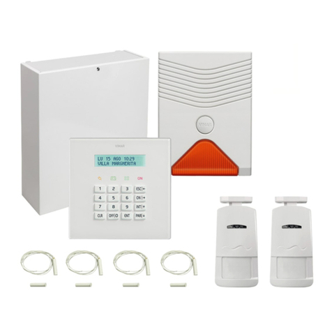
By-alarm Plus keypad with monochrome LCD display, 12 Vdc power supply,
23 backlit keys, 5 status LEDs, surface mounting.
The keypad is the most complete peripheral for managing the burglar alarm system. The
installer assigns the areas and system zones to each keypad. Users with the appropriate code
can access and operate these areas and zones. The graphic display shows all the information
through a user-friendly interface that is easy to navigate.
CONNECTIONS
Connect it to the control unit with a 4-wire (or more) shielded cable.
Caution: Connect the shield to one of the earth (or GND) terminals at the control unit end
only, and ensure that it follows the entire BUS without being connected to earth at any
other point.
Connect the keypad to the “+ D S -” terminals on the control unit.
INSTALLATION
1.Choose a suitable location for installation.
2.Detach the front panel from the bracket with the terminals to open the keypad.
3. Fasten the bracket to the wall. The bracket can be fitted to various types of flush mounting
box (round, square and rectangular) or directly to the wall.
4.Route the cables through the cable outlet holes and wire them to the terminal block.
5.Mount the keypad on the bracket, inserting the retaining tabs into their seats first and then
pushing the keypad towards the wall.
6.Insert the fixing screw in position.
NAVIGATION KEYS
To open the User or Installer menu
To return to the previous menu
To enable/disable or activate/deactivate
To manage outputs that can be activated manually
LED INDICATIONS
LED status: OFF
Red LED All keypad areas are deactivated
Yellow LED There are no active faults
Blue LED All zones of the keypad areas are at rest
Violet LED All zones of the keypad areas are enabled in the system
Green LED There is no primary power supply (230V~)
LED status: ON
Red LED Al least one keypad area is activated
Yellow LED There is at least one active fault
Blue LED Zones in the keypad areas are open
Violet LED At least on of the keypad areas is disabled or inhibited
Green LED There is primary power supply (230V~).
LED status: flashing slowly
Red LED
All keypad areas are deactivated.
There is an alarm memory/tampering in at least one keypad area, or
there is a system alarm memory.
Yellow LED There is at least one active fault or a fault memory, or remote access has
been enabled for the installer.
LED status: flashing fast
Red LED
At least one keypad area is activated.
There is an alarm/tampering in at least one keypad area, or there is a
system alarm.
Yellow LED There is at least one active fault.
Green LED There is no primary power supply (230V~) and a low battery condition
has been detected.
BUZZER INDICATIONS
The keypads emit acoustic signals to indicate the various system statuses.
Entrance, exit and warning times are indicated for the enabled areas.
If programmed from the control unit, the keypads can also repeat alarm indications on the buzzer.
EMERGENCY FUNCTIONS
Special key combinations on the keypad can be used to activate the following indications on
the control unit:
• Fire Emergency
• Health Emergency
• Public Safety Emergency
Activating any of these emergency conditions activates outputs and sends alerts, as pro-
grammed in the control unit.
Press the keys highlighted in grey for at least 3 s.
Key combination Indication
Fire Emergency
Health Emergency
Public Safety Emergency
DISPLAY
The 192 x 64 pixel LCD display is backlit, and its brightness can be adjusted from the corre-
sponding menu.
The contents displayed vary with the situation or current control unit status, i.e.:
• Rest, the normal operating condition of the control unit, without any active alarm, tampering
or fault indications. In this condition, the first line of the display shows the user logged into the
system and the current date, the second line shows the current time, and the third line shows
a set of functions that can be activated with the corresponding function keys. The functions
that can be activated depend on the system status and configuration.
• Zone alarm or tampering, when the control unit detects a violation or indicates a violation in
a zone, either an intrusion or tampering with a device. In this state, the first line of the display
indicates the alarm type: INTRUSION, FIRE, TAMPER or ENVIRONMENT ALARM, and the
second line shows the name of the zone with the alarm. If more than one zone has an alarm,
the first one to be violated will be displayed.
• Maintenance, the operating state in which the control unit is set for maintenance or program-
ming. In this condition, the first line of the display shows the installer logged onto the system
and the current date, the second line shows the “Maintenance” state, and the third line shows
a set of functions that can be activated with the corresponding function keys. The functions
that can be activated depend on the system status and configuration.
Status icons shown on the display
This is shown in the menu pages to indicate that there is an active alarm. On
opening the alarms list, the icon flashes and may be followed by the name of
the areas with an alarm.
On opening the alarms list, if the icon flashes next to the zone with the alarm,
it indicates that the alarm condition still persists (e.g. the zone was violated
and is still open).
It is shown in the middle of the display, in the keyboard home page, after:
- writing in the system with the By-alarm Plus Manager software;
- modification of descriptions:
- after a reset to factory settings.
For the user, it indicates an alignment phase between the control unit and the
keyboards during which the keyboard cannot be used (it does not respond to
key pressing).
