Climecon CLEANMASTER Series User manual
INSTALLATION MANUAL
AND QUICK GUIDE
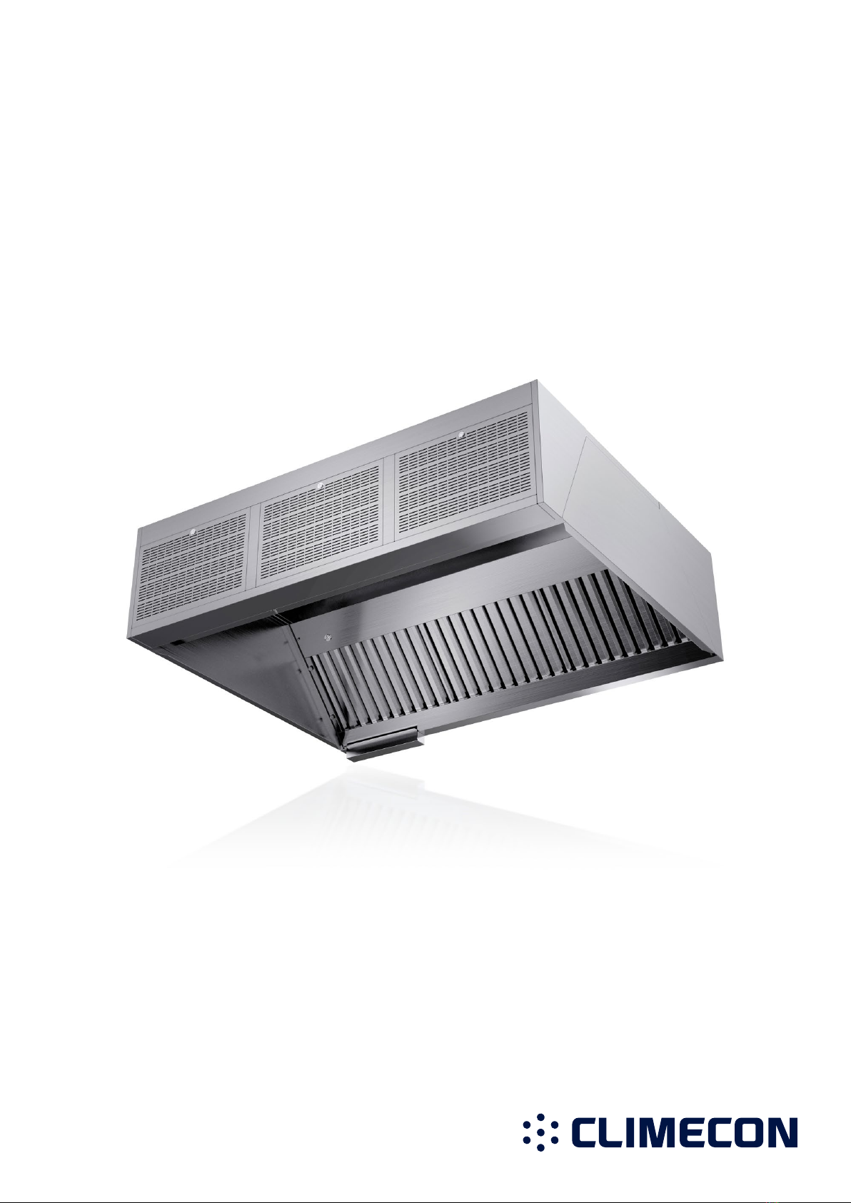
CleanMaster®
climecon.fi
09.20
climecon.fi
2
Lämmittäjänkatu 4 A, 00880 Helsinki, FINLAND · Tel. +358 (0)20 198 6600
© Climecon
CONTRACTOR!
IMPORTANT!
READ THE INSTALLATION MANUAL CAREFULLY
Check at least the following sections to ensure an acceptable installation.
1. When you first start the device, determine its purpose of use and the
number of separators. See page 10.
2. CHECK THAT THE SLIDESAFE SWITCH IS WORKING.
When the switch is opened (downward position),
the UV system has to shut down.
3. CHECK THAT THE SEPARATORS
HAVE BEEN INSTALLED CORRECTLY!
The upper part of the separator has
a ‘tongue’ which should be placed
in the groove in the upper part of
the grease chamber. The UV separator
is formed of two parts.
4. CHECK THAT THE INSTRUCTIONAL LABELS ENCLOSED TO
THE DELIVERY are installed in the immediate vicinity of the hoods.
5. USERS MUST BE TRAINED TO OPERATE THE DEVICE and this
training should also be written down for the client.
6. MAKE SURE THAT THE COMMISSINING RECORD HAS BEEN
FILLED IN CORRECTLY and that all the necessary tests have been per-
formed and recorded!
You can also order the commissioning, installation, (excluding hauling and
HVAC contract work) training and maintenance services directly from Climecon.
Lämmittäjänkatu 4 A
00880 HELSINKI
Puh. +358 20 198 6600
climecon.fi
Please make sure that the fold
and the three holes are
facing upwards!

climecon.fi
3
Lämmittäjänkatu 4 A, 00880 Helsinki, FINLAND · Tel. +358 (0)20 198 6600
© Climecon
Contents
1. General....................................................................................................................4
2. The content of CleanMaster® hood deliveries: .....................................................5
3. Warnings.................................................................................................................6
4. CleanMaster quick guide........................................................................................7
5. Installation instructions for CleanMaster® hoods.................................................8
6. Electrical connections of the CleanMaster hood...................................................9
7. Operation modes (A, B or C)...................................................................................10
8. Starting the CleanMaster hood..............................................................................11
9. Disconnecting the grease separators ....................................................................13
10. Changing the UV lamp............................................................................................14
Adjustment instructions for CleanMaster® hoods................................................15
12. K value table of CleanMaster®-hoods ...................................................................16
13. Installing the UV lamp............................................................................................17
14. Installing the grease separators and locking the SlideSafe safety lock ...............18
15. Maintenance instructions for CleanMaster® hoods..............................................19
...................................................23
17. Climecon CleanMaster® – updating an external controller..................................24
.........................................................................26

climecon.fi
4
Lämmittäjänkatu 4 A, 00880 Helsinki, FINLAND · Tel. +358 (0)20 198 6600
© Climecon
1. General
These installation, adjustment and maintenance instructions apply to Climecon CleanMaster® hoods.
The Climecon CleanMaster® hood range includes:
• CleanMaster® hoods
Read these installation, adjustment and maintenance instructions carefully through before installing
and using the product. If you have any questions regarding the product’s installation or use, please
contact Climecon’s customer service.
Climecon Oy
Lämmittäjänkatu 4 A
00880 HELSINKI
Puh 020 198 6600
Fax 020 198 6609
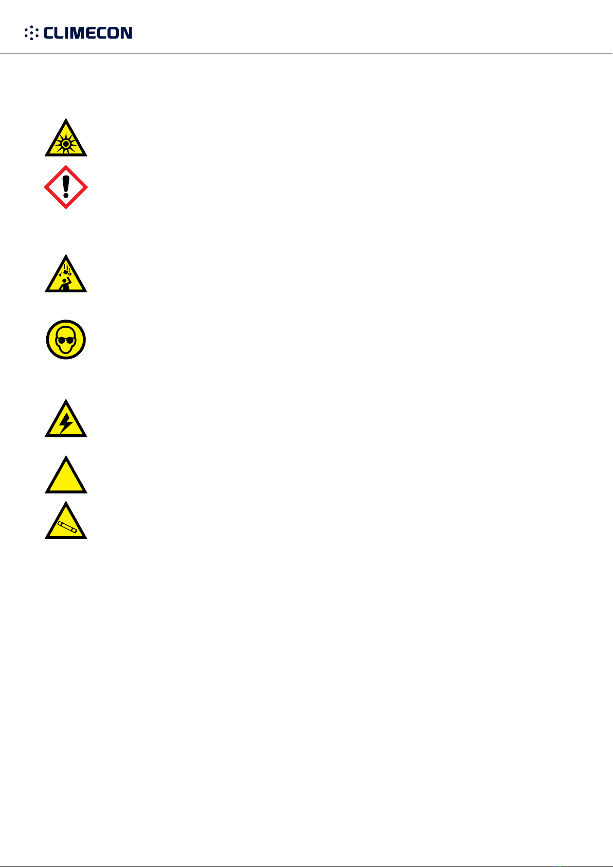
1.1 Occupational safety and the product’s safe installation
Use that violates the user or safety instructions, neglecting these or improper use of UV devices
may lead to personal injury!
NOTE! The electrical connections of the CleanMaster® system can only be performed by an author-
UV lamps are used.
No replacement parts or UV lamps other than original ones or ones ordered from Climecon can be
+358 (0)20 1986 600)
Ultraviolet radiation and ozone are hazardous to health! Skin and eyes are especially vulnerable to
ultraviolet radiation. The radiation can cause burns and long-term exposure can lead to cataracts.
in case of quartz shards that
may occur if a UV lamp breaks.
1.2 Receiving a delivery
Check that the delivered batch matches the order and that all the parts listed in the cover letter have
to replacing products that have been installed in violation of the installation instructions.
If any problems arise, please contact Climecon’s customer service!

climecon.fi
5
Lämmittäjänkatu 4 A, 00880 Helsinki, FINLAND · Tel. +358 (0)20 198 6600
© Climecon
2. The content of CleanMaster® hood deliveries:
The delivery includes:
•
• Grease separators
• Grease tray/trays
•CCM control unit and possible auxiliary cabinets
•
•
•
•
•Warning labels for the hood
•Installation, adjustment, user and maintenance instructions
The delivery does not include:
•Voltage supply line (e.g. MMJ 3G2.5) for the UV control unit
•
•The UV lamps’ voltage supply from the UV control unit’s terminal block to the hood’s quick con-
nectors (e.g. control cable Ölfex 4 x 1.5mm2)
• Mounting accessories
• Cables to the SlideSafe safety lock
climecon.fi
6
Lämmittäjänkatu 4 A, 00880 Helsinki, FINLAND · Tel. +358 (0)20 198 6600
© Climecon
3. Warnings
Danger of ultraviolet radiation and ozone!
Your skin and eyes are especially vulnerable to ultraviolet radiation. The radiation can cause
burns, and long-term exposure can lead to cataracts; ultraviolet radiation is detrimental to the
lens of the eyes and corneas.
Read through the user instructions carefully!
Danger of falling!
Protective goggles and gloves must be worn during installation and
maintenance!
actions. Quartz shards may occur if a UV lamp breaks.
Danger of electric shock!
The electrical connections of the CleanMaster® system can only be performed by an authorised
electrician.
Always switch the system o before performing any maintenance!
Only Climecon’s own replacement parts and UV lamps can be used in
the CleanMaster® system.
are used. No replacement parts or UV lamps other than original ones or ones ordered from
Climecon can be used for the device.
(Tel. +358 (0)20 1986 600)
OFF

climecon.fi
7
Lämmittäjänkatu 4 A, 00880 Helsinki, FINLAND · Tel. +358 (0)20 198 6600
© Climecon
1. Connector for the external controller
2. ModBUS connection point
3. Filter (to be replaced as necessary)
4. Fan (check functionality during maintenance)
5. Electrical supply 230 V LN + protective earth
6.
Climecon CleanMaster controller’s instructions:
The screen also displays the amount of air (l/s)
7. Automation points, see separate instructions:
8.
9.
-
trol device by opening the
NOTE! Remember to take
into account the loose cable
needed for opening the
hatch.
1. Exhaust chamber’s measuring connection
(check the K value from the label inside the hood)
2. UV-approved grease separators
3.
and control air (check the K value from the label inside
the hood)
4. CleanMaster quick guide
CleanMaster features integrated technology for the UV use. A separate control device is not needed. The hood
control device to open. The light has a separate cord that needs to be connected to the lighting group.
1. 2.
3.
4. 5.
6.
7.
8.9.
10.
1.
2.
3. Exhaust air
4. Integrated control device
5. Carrying points M8 in the corners (also in the middle
for the larger size classes, Z iron included to facilitate
mounting)
6. Easily removable supply air slats for maintenance
7. Supply air
8.
9.
10.
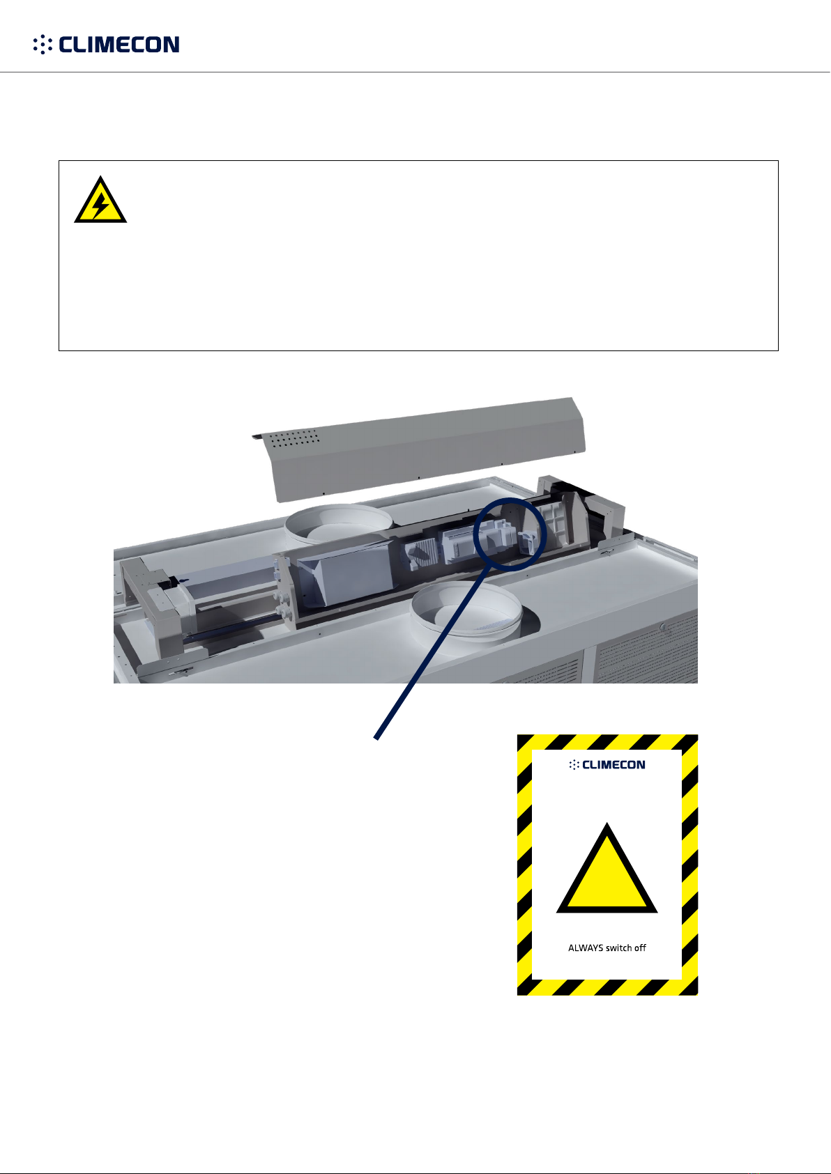
Danger of electric shock!
Electricity supply to the control device
NOTE! Electrical connections may only be made by a professional electrician.
- The light is connected to the light group (connection cable as factory equipment)
Always switch the system o before performing any maintenance!
2. 3.
4.
5.
6.
7.
8.
9.
1.
The control device’s hatch can be opened by
3.
2.
1.
OFF

climecon.fi
8
Lämmittäjänkatu 4 A, 00880 Helsinki, FINLAND · Tel. +358 (0)20 198 6600
© Climecon
A
A
C
C
C
C
D
A
A
A
A A
A
B
B
B
B
C
C
C
C
D
E
AR
E
3.1 Installing the hood
1. Mount the threaded rods (A) to the ceiling
at the correct points. NOTE! The threaded
rods are not included in the delivery!
If the hood is open on the side (AR), the
hood also needs to be mounted from the
middle of its open side (B).
2.
3.
threaded rod and the hood.
4. Check that the hood is vertical.
5. Remove any possible transport supports.
6. Connect side-by-side hoods to each other
by the holes in the hood’s top edge (E),
using an M6 bolt and nut.
7. If the unit in question has several hoods,
mass, such as 3MTM.
Hybrid glue/sealant mass 760 UV
5. Installation instructions for CleanMaster® hoods
DANGER
OF FALLING DURING
PROTECTIVE GOGGLES AND GLOVES MUST BE WORN
DURING INSTALLATION AND MAINTENANCE!
climecon.fi
9
Lämmittäjänkatu 4 A, 00880 Helsinki, FINLAND · Tel. +358 (0)20 198 6600
© Climecon
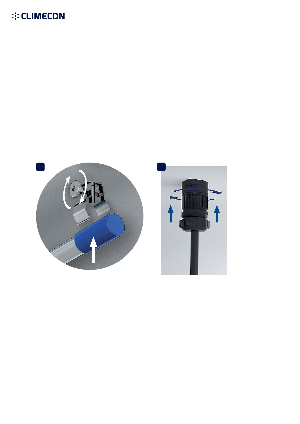
6. Electrical connections of the CleanMaster hood
Danger of electric shock!
Electricity supply to the control device
NOTE! Electrical connections may only be made by a professional electrician.
been named
- The light is connected to the light group (connection cable as factory equipment)
Electricity supply connections:
Electricity supply is brought to the casing through a strain
reliever. Note, the opened hatch may turn.
Electricity supply has to be connected to the hood/hood
included in the delivery must be attached to it!
!
CleanMaster
huuvan/ilmanvaihtokaton turvakytkin
hood/ventilation ceiling safety switch
Katkaise virta AINA ennen
huollon aloittamista.
before maintenance.
climecon.fi/clm

climecon.fi
10
Lämmittäjänkatu 4 A, 00880 Helsinki, FINLAND · Tel. +358 (0)20 198 6600
© Climecon
7. Operation modes (A, B or C)
A: STAND-ALONE IN MASTER MODE
•local monitoring
•one display
•Physical BAS control
B: LOCAL GROUP, MASTER
+ 1-9 SLAVES
•local monitoring (all units in the group)
•one display
•Physical BAS control (master)
C: OPERATED AND MONITORED
BY A BAS
•Local monitoring only for connected hood
•1…n display if local monitoring needed
•Physical BAS Control (overrides ModBus)
•Control via ModBus
•Modbus master not supplied
Building automation (physical)
• alert
• permission to run
Building automation (physical)
• alert
• permission to run
Building automation (physical)
• alert
• permission to run
• needed for all units
Master mode
Master mode
ModBus master
(building automation)
All in slave mode
+ ModBus address
ModBus compatible cable
ModBus compatible cable
Slaves 1..9
CAT5, RJ45
CAT5, RJ45
A
B
C

climecon.fi
11
Lämmittäjänkatu 4 A, 00880 Helsinki, FINLAND · Tel. +358 (0)20 198 6600
© Climecon
8. Starting the CleanMaster hood
-
tion to ensure its correct operation.
Hood connections in a Master/Slave assembly.
-
Datajamak 2x(2+1)x0.24. The ModBus data cable is connected to the
control device’s ModBus channel 2, to the points:
3: protection
1. Choose your language
2. Master/Slave
Climecon CleanMaster can be the device’s Master or
Slave device.
If the device in question is a separate hood or a group of
-
ter. Other settings do not need to be changed.
-
Master from the main controller and then the Slave
Slave devices during the initial start, and must be deter-
mined a Slave address from 1 to 9.

climecon.fi
12
Lämmittäjänkatu 4 A, 00880 Helsinki, FINLAND · Tel. +358 (0)20 198 6600
© Climecon
3. Number of separators
The measurement of air quantity is based on meas-
uring the chamber pressure. To achieve the correct
1–12 separators.
to the logic. If there are ‘blinds’ in the hood, they are
not included in the number of separators. For exam-
ple, the maximum number of separators in a hood
4. Approve the selections by clicking
-
in the OFF position. When the UV lamp is on, the lamp
For other settings than the hood controller’s basic settings, please read through the separate user manual,
climecon.fi/clm.
The Climecon CleanMaster system can also be connected to the external ModBus control device.
map is available through Climecon Oy’s customer service.

climecon.fi
13
Lämmittäjänkatu 4 A, 00880 Helsinki, FINLAND · Tel. +358 (0)20 198 6600
© Climecon
1
4 5
2 3
9. Disconnecting the grease separators
OFF
ULTRAVIOLET RADIATION HAZARD WEAR PROTECTIVE EYEWEAR DURING
INSTALLATION AND MAINTENANCE
1.
2.
the separators.
3.
NOTE! If the CleanMaster® system has not been closed from the CCM control unit as instructed, the
4.
5
6.3 Replacing the fluorescent tubes of lights
1.
2.
3. Check that the sealants are undamaged.
4. Reinstall the cover glass.

climecon.fi
14
Lämmittäjänkatu 4 A, 00880 Helsinki, FINLAND · Tel. +358 (0)20 198 6600
© Climecon
upper position and then retightening them.
Install all grease separators back into the hood.
as the last.
Attach the UV lamp’s electrical
connector (quick connector) to
the hood’s ceiling and tighten it
the brackets and tighten the
hand knobs by turning them
Replace the UV lamp. Only
Climecon’s UV lamps can be
used in the CleanMaster® sys-
Climecon’s customer service.
Climecon’s customer service,
tel. +358 (0)20 1986 600.
10. Changing the UV lamp
4
8
12
910 11
5 6 7
2 3
ULTRAVIOLET RADIATION HAZARD
Please deliver your old UV
lamp to a collection point
and detach the UV lamp from the
brackets.
then the others.
Disconnect the UV lamp’s elec-
trical connector (quick connec-
tor) from the hood ceiling by
any maintenance actions!
Open the SlideSafe safety lock by loosening the hand knobs and
OFF
1
WEAR PROTECTIVE EYEWEAR DURING
INSTALLATION AND MAINTENANCE

climecon.fi
15
Lämmittäjänkatu 4 A, 00880 Helsinki, FINLAND · Tel. +358 (0)20 198 6600
© Climecon
123,0
123,0
1
2
6
7
5
3 4
11. Adjustment instructions for CleanMaster® hoods
Adjusting the exhaust air:
•Separate the grease separator cartridges (1) care-
trough.
•
•Make the suction opening larger or smaller by mov-
ing the damper in its slide rails.
•Install the separator cartridge/cartridges in place
properly.
•Measure the pressure loss from the chamber’s
measuring connection (2).
•Repeat the steps above if necessary.
•
check that the separator cartridges are properly
installed.
Adjusting supply air
•First, measure the pressure loss from the sup-
ply air chamber’s measuring connection (5).
•
•Supply air can be controlled by turning
the control damper (7) inside the supply
air chamber.
•
•Reinstall the supply air modules (6).
•Measure the pressure loss from the supply air
chamber’s measuring connection (5).
•Repeat the steps above if necessary.
Adjusting the control air
control air. These adjustments can be made
the hand knobs.
4.1 Adjusting supply air, exhaust air and control air

climecon.fi
16
Lämmittäjänkatu 4 A, 00880 Helsinki, FINLAND · Tel. +358 (0)20 198 6600
© Climecon
12. K value table of CleanMaster®-hoods
Exhaust air/Number of separators (pcs)
Hood model 1 2 3 4 5 6 7 8 9 10 11 12
CleanMaster® 18,5 37 55,5 74 92,5 111 129,5 148 166,5 185 203,5 222
StandardPlus, grease 21,6 43,2 64,8 86,4 108 129,6 151,2 172,8 194,4 216 237,6 259,2
StandardPlus, condensation 22,7 45,4 68,1 90,8 113,5 136,2 158,9 181,6 204,3 227 249,7 272,4
Supply air/Hood width (mm)
Height of the hood 800 1000 1500 2000 2500 3000
H=560 mm 28 45 67 90 112 135
H=400 mm 22 42 64 85 106 127
H=300 mm 22 33 49 66 82 99
Control air/Hood width (mm)
Adjustment position 800 1000 1500 2000 2500 3000
Maximum (Fully open) 1,4 2,8 4,2 5,6 7,0 8,4
Minimum (Half open)* 0,6 1,2 1,8 2,4 3,0 3,6
*Recommended to be used if supply air pressure exceeds 15Pa.
climecon.fi
17
Lämmittäjänkatu 4 A, 00880 Helsinki, FINLAND · Tel. +358 (0)20 198 6600
© Climecon
1. Attach the UV lamp carefully to the fastenings in the hood’s grease chamber.
NOTE! Centre the lamp’s blue plastic parts to the fastenings. Tighten the fasten-
2.
hood’s ceiling. Rotate the connector’s locking ring.
NOTE! Attach the instruction labels (included in the delivery) for changing the UV
lamp and maintaining the hood in a visible place near the CCM control unit.
3.
and roll up any extra cords so that they do not lie in the grease.
NOTE! Do not attach the cords directly to the lamp!
13. Installing the UV lamp
21

climecon.fi
18
Lämmittäjänkatu 4 A, 00880 Helsinki, FINLAND · Tel. +358 (0)20 198 6600
© Climecon
1. Install the hood’s outermost grease
-
Remember to also install the grease trays
on the bottom of the exhaust air chamber.
2.
right.
3.-
ing the hand knobs to their upper position
and then retightening them.
NOTE!
start if the SlideSafe safety lock has not
been locked properly.
14. Installing the grease separators and locking
the SlideSafe safety lock
SWITCH THE SYSTEM OFF BEFORE PERFORMING
ANY MAINTENANCE ACTIONS
OFF
1
2
3

climecon.fi
19
Lämmittäjänkatu 4 A, 00880 Helsinki, FINLAND · Tel. +358 (0)20 198 6600
© Climecon
-
ness of kitchen equipment. The cleaning frequency of Climecon’s CleanMaster® hoods depends om
their use and should be determined based on their utilisation rate.
(pH > 11) should be avoided. Climecon’s UV lamps do not need to be cleaned in normal conditions.
5.1 Cleaning the hoods
1.
2. Clean the hood’s edge gutters and grease trays.
3.
4. Clean the exhaust air chamber if necessary. See the instructions for detaching the grease separators
in chapter 5.2 Detaching the grease separators.
5. Clean the supply air modules if necessary.
15. Maintenance instructions for CleanMaster® hoods
climecon.fi
20
Lämmittäjänkatu 4 A, 00880 Helsinki, FINLAND · Tel. +358 (0)20 198 6600
© Climecon
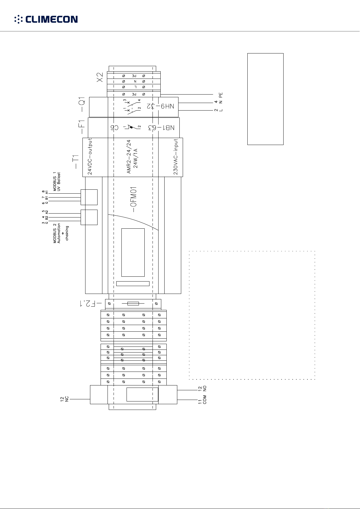
R10 relay / potential free
“General fault” –information
for an automation
PIN 11: COM (Common)
PIN 12: NC (Normal Closed)
PIN 14: NO (Normal Open)
R10
X10
X10 Connection points
24V DC output for building automation
USE WITH A GALVANIC ISOLATED DIGITAL INPUT (DI)
PIN 11 Common plus (24DC out +)
PIN 23 Unit is running
PIN 24 General fault
PIN 25 Sevice (15 500 h -> ON/OFF 1s interval)
(16 000 h -> ON)
PIN 26 UV fault (Lamp or ballast fault)
PIN 27 SlideSafe not armed
PIN 28 Automation permit
Pressure transmitter: PIN 5-6
PIN 5 2-10 V (range: 0-100 Pa)
PIN 6 GND
Permit to run (building automation or local switch)
USE WITH A POTENTIAL FREE (DO)
PIN 3-4 (DI)
INPUT Q1
230VAC IN, 50Hz
C10A
USE THIS POINT TO ELECTRIFY
THE CLEANMASTER HOOD
ATTENTION!
USE ALLWAYS SAFETY SWITCH
NOTE:
THE LUMINAIRE IS ELECTRIFIED
SEPARETELY.
Other manuals for CLEANMASTER Series
1
Table of contents
Other Climecon Ventilation Hood manuals


Popular Ventilation Hood manuals by other brands


Electrolux
Electrolux EFP 6400 Operating and installation instructions

Klarstein
Klarstein 10026951 manual

Victory Range Hoods
Victory Range Hoods Victory SKY instruction manual

Beko
Beko HCA62320W user manual

Omega
Omega ORU50XL instruction manual

Forte
Forte KEIRA Installation, operating and maintenance instructions