Climer ECOHEAT TD EH260TDSH4 User manual
INSTALLATION AND USER MANUAL
ECOHEAT TD
EH260TDSH4

INSTALLATION AND USER MANUAL
ECOHEAT TD
V0REV1EN0422

INSTALLATION AND USER MANUAL
ECOHEAT TD
V0REV1EN0422
1. INTRODUCTION............................................................................................................1
2. GENERAL INDICATIONS.............................................................................................1
3. TECHNICAL INFORMATION ......................................................................................3
4. INSTALLATION STEPS ................................................................................................5
5. THERMODYNAMIC SOLAR PANEL INSTALLATION...........................................7
6. PLACING ECOHEAT......................................................................................................8
7. CONNECTION BETWEEN ECOHEAT TD AND PANELS ......................................9
8. HIDRAULIC CONNECTION ......................................................................................12
9. ELECTRICAL CONNECTION ....................................................................................13
10. COMISSIONING. CONTROLLER..............................................................................14
11. WARRANTY CONDITIONS ......................................................................................24

INSTALLATION AND USER MANUAL
ECOHEAT TD
1 V0REV1EN0422
1. INTRODUCTION
This product, has been manufactured according to the European Quality Standards,
incorporates prime grade materials and its correct working has been tested before it leaves our
facilities.
Through this Installation and User Manual, you will be guide towards the correct and safety
installation of the product. It is necessary to carefully read this manual before making any
handling to avoid problems arising from the misuse of the product.
The company reserves the right to modify the information included in this document at any
time without prior notice.
2. GENERAL INDICATIONS
2.1. Safety notes
The incorrect or inappropriate use of this product could lead to hazardous situations, causing
damage or injuries to the user, third parties or even to the product itself or material goods.
-The installer has the responsibility to install the minimum safety devices (hydraulic and
electrical) set out in this Manual. In case of failure, the lack of any device may cause
burns or other injuries.
-The installer has the responsibility to inform the user about the function and placement
of the safety devices installed into the device and the installation.
-The water outlet temperature could reach 62 degrees. Do not touch the pipes while
the system is working to avoid any risk of burns.
2.2. Installer’s qualification
Since the installation of the ECOHEAT TD involves handling coolant as well as carry out
welding work, it is needed the technical staff have the official certification that accredits them
as authorized to handle coolants.
The installer must explain the user the application of the product and the use and
management of the unit, and he should provide the user all the documentation supplied
with the equipment.

INSTALLATION AND USER MANUAL
ECOHEAT TD
2 V0REV1EN0422
2.3. Package contents
The ECOHEAT system comprises the following components:
-Thermodynamic panel
-Anchoring elements
-ECOHEAT TD
-Silent-Blocks
-User Manual
2.4. Indications about transport and unpacking the unit
The unit is supplied packed into a wooden pallet properly secured to prevent damage
during transport.
The material used to the packing are recyclables, so dispose it in an appropriate container.
Use a forklift or hand pallet truck to transport the unit to the installation site, always
introducing the forks into the bottom of the pallet being careful not to damage the unit.
In case you identify any damage at the time of the reception of the unit, it is mandatory to
register it in the reception note of the transport company, and then, submit the complaint.
For this reason, it is recommended to make a thorough visual inspection of the goods before
signing the reception note.
INSTALLATION AND USER MANUAL
ECOHEAT TD
3 V0REV1EN0422
3. TECHNICAL INFORMATION
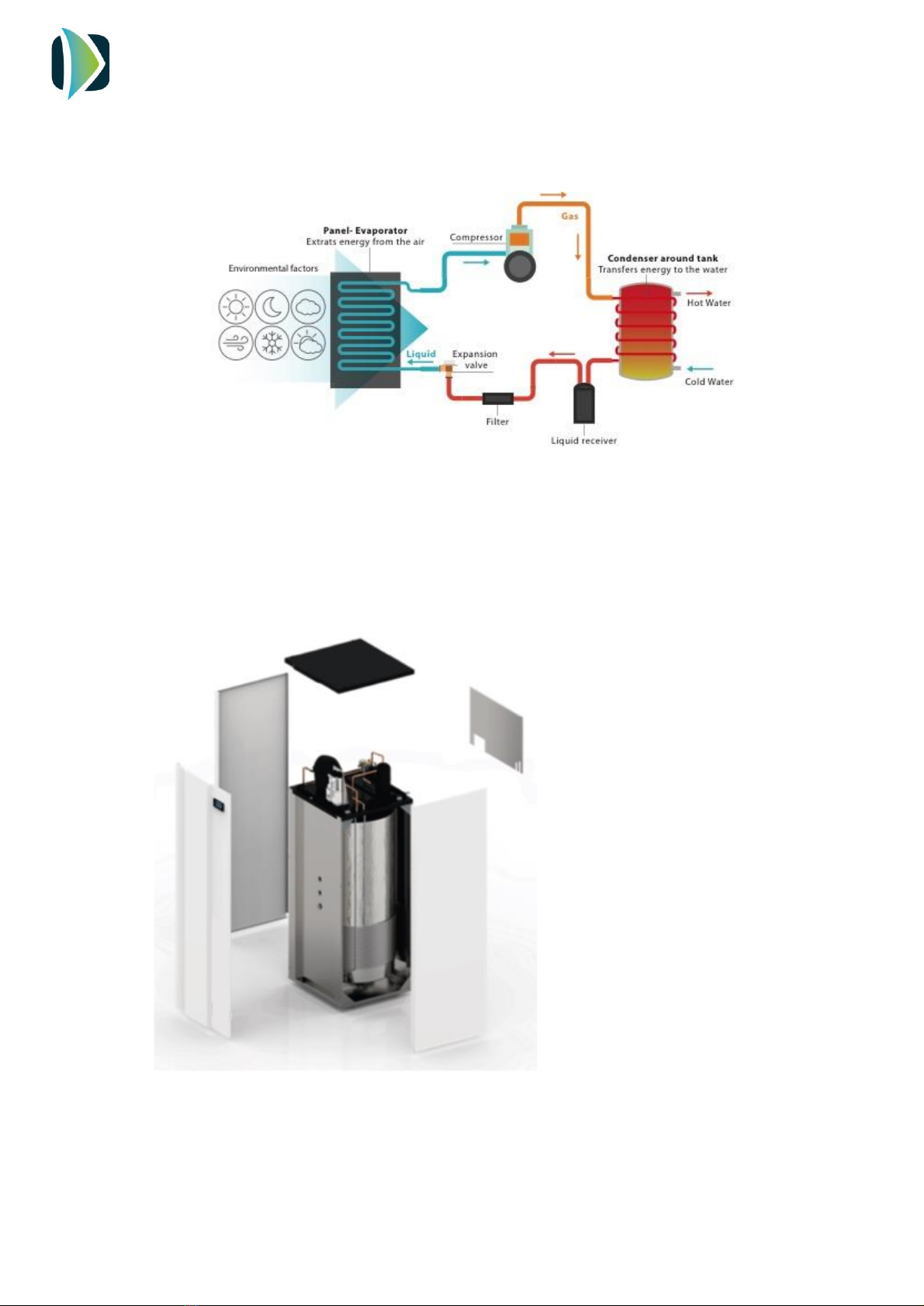
3.1. Operating Principle
Figure 1. Operating principle
3.2. Dimension drawings
It is possible to remove the side and front casing access easily to any part of the system.
Figure 2. Exploded view
INSTALLATION AND USER MANUAL
ECOHEAT TD
4 V0REV1EN0422
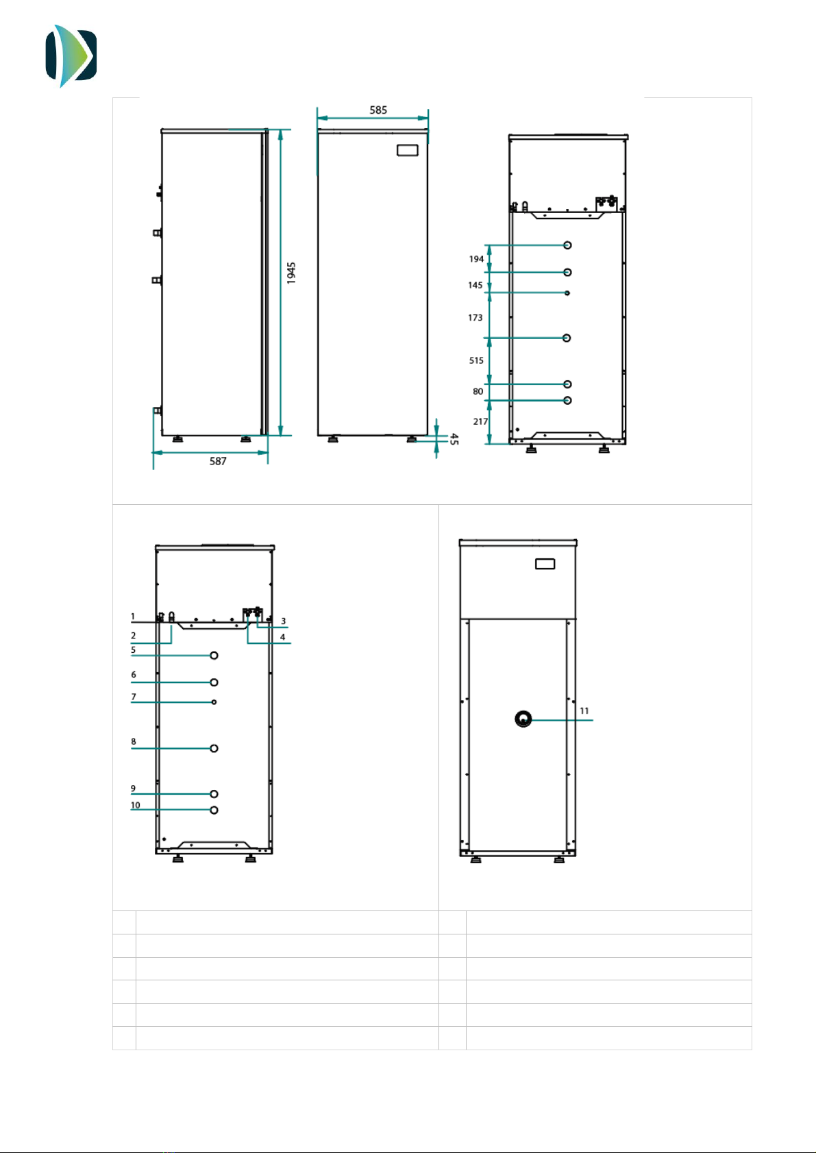
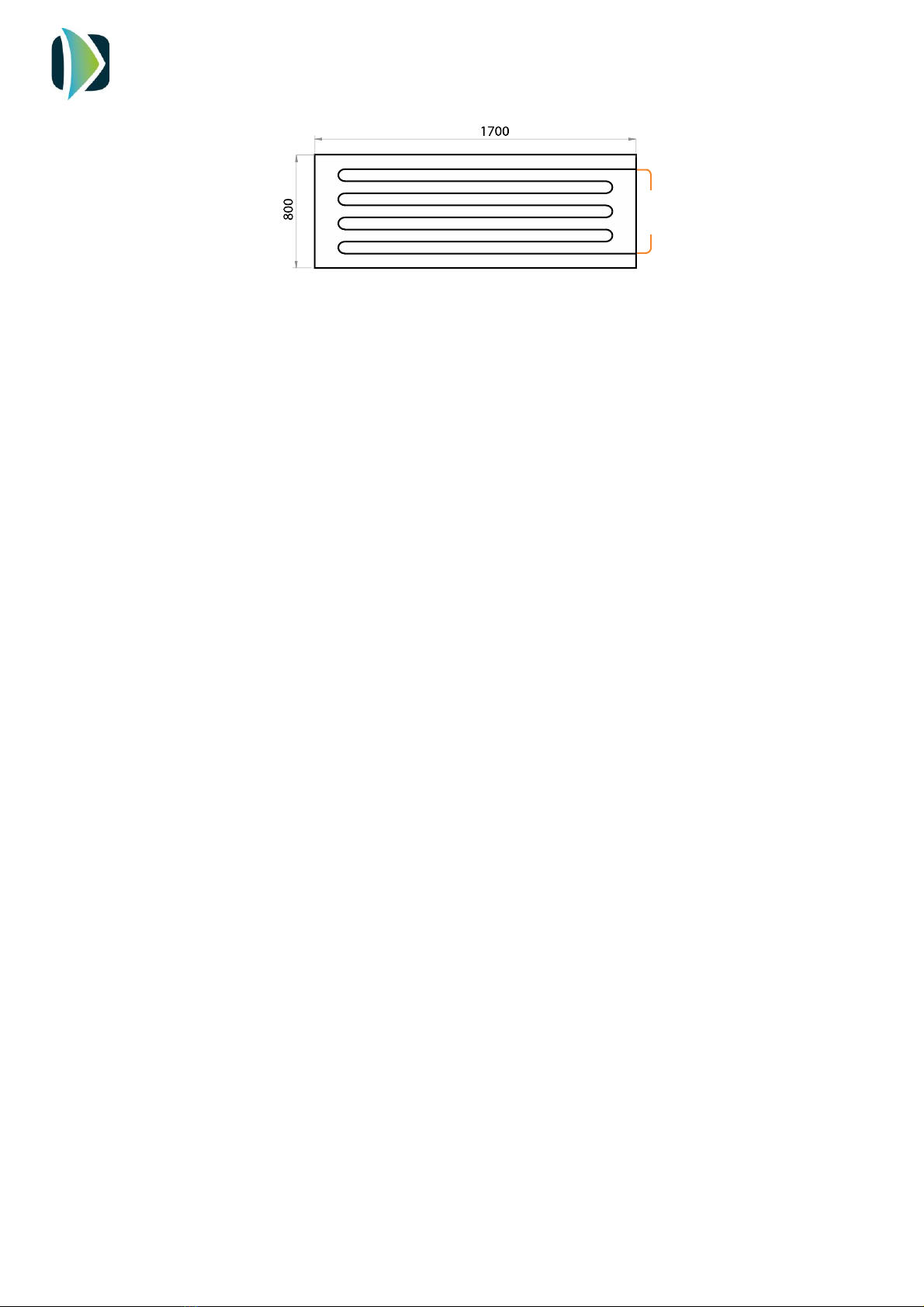
Figure 3. Dimensions, mm
Figure 4. Back connections
Figura 5. Front connections
1
Power supply 230 V/1ph/50 Hz
7
Temperature pocket (Boiler temperature probe)
2
Condesate drain
8
Coil outlet, ¾’’
3
Refrigerant inlet (gas), 1/2‘’
9
Coil inlet, ¾’’
4
Refrigerant outlet (liquid), 3/8”
10
Cold water inlet, ¾’’
5
Hot water outlet, 3/4‘’
11
Electrical heater, 1500 W / Temperature probe
6
Circulation connection, 3/4’’

INSTALLATION AND USER MANUAL
ECOHEAT TD
5 V0REV1EN0422
3.3. Technical data
4. INSTALLATION STEPS
Before starting the installation, check the availability of all the necessary components and tools:
-Copper tee for gas line: 2 inlets 3/8 - 1 outlet 1/2
-Copper tee for Liquid line: 1 inlet 3/8 - 2 outlets 1/4
-High and low pressure manometers
-Vacuum pump
-Scales
-Nitrogen bottle
-Refrigerant quality copper pipe
-Pipe-cutter
-Tube bender
Model
EH260TDSH4
Cylinder
Capacity, L
260
Maximum operating pressure, bar
6
Heat pump data
Energy Efficiency Class
A
Load profile
XL
Heating capacity range *, W
2860 - 5120
Input power range *, W
900 - 1120
Maximum temp. HP, ºC
60
Maximum temp. electric element, ºC
62
Coolant
R134A
Refrigerant inlet/ outlet, inch
1/2 - 3/8
Electric data
Power supply, V/ph/Hz
230/1/50
Electric element power, W
1500
Maximum current, A
13
Maximum power absorbed, W
2800
Thermodynamic panel
Number of panels
2
Dimensions, mm
1700 x 800
Maximum operating pressure, bar
10
Refrigerant inlet/outlet, inch
1/4 - 3/8

INSTALLATION AND USER MANUAL
ECOHEAT TD
6 V0REV1EN0422
-Pipe expander
-Welder
-Copper Rods (40 % Silver)
-Insulating hose
-Drill
-Screwdriver
-Hydraulic installation components
-Electric installation components
Once it has been checked that it is available all the necessary components and tools, the
installer should follow the next steps:
1. Placing and anchoring panels
2. Joining and welding the refrigerant pipes
3. Placing the ECOHEAT TD
4. Joining and welding liquid and suction line between ECOHEAT TD and panel
5. Nitrogen pressure test (maximum 10 bar)
6. Vacuum
7. Filling refrigerant installation
8. Hydraulic installation
9. Electric installation
10. Commissioning
11. Adjustment of refrigerant load
INSTALLATION AND USER MANUAL
ECOHEAT TD
7 V0REV1EN0422
5. THERMODYNAMIC SOLAR PANEL INSTALLATION
5.1. Site selection
The choice of the installation site of the thermodynamic panel is a key factor in the final
performance of the unit. For this reason, we recommend following the indications in order
to achieve the best performance:
-South orientation is indeed the best to take the maximum advantage of solar radiation.
Panel may also have other orientations, but northerly orientation is the worst to receive
solar radiation.
-Inclination: The minimum inclination of the panel is 15º in order to ensure the correct
evaporation of the coolant. It is recommended to install the panel with an inclination
between 45º and 90º.
-Orientation: It is possible to install the panel both in vertical and horizontal position
-Distances to ECOHEAT TD:
The maximum allowed distance from the panel to the ECOHEAT TD is 10 meters.
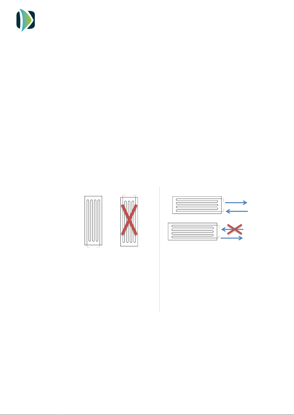
In the picture below is shown the dimensions of the panel:
When the panel is installed in vertical
position, always the inlet and outlet
connection has been at the bottom.
(It is not allowed to install the reverse)
If the panel is installed at horizontal
position, refrigerant inlet pipe
should be connected into the
bottom connection.
INSTALLATION AND USER MANUAL
ECOHEAT TD
8 V0REV1EN0422
5.2. Anchoring panel
Beside the panel, it is supplied a bag with anchoring elements that contains the following
pieces:
-6 x Aluminium support (L shape)
-6 x Screws M5
-12 x Nuts M5
-18 x Washer 5
-18 x Sheet Metal Screws
-18 x Blocks M6
Anchor the panels using the lateral and front holes to the suitable surface.
6. PLACING ECOHEAT
The place where the system will be installed should allow an easy access in order to make
maintenance work or inspection.
Beside these factors, it is important to take into account the following indications regards the
installation site:
-The system has been designed and manufactured for it indoors utilization. In case the
system must be placed outdoors, it must be protected against the adverse weather
conditions (direct solar radiation, rain, snow…)
-Try to place ECOHEAT TD as near as possible of the panels and near to the buffer tank.
-Installer must install the supplied Silent blocks to avoid the transmission of vibration.
INSTALLATION AND USER MANUAL
ECOHEAT TD
9 V0REV1EN0422
7. CONNECTION BETWEEN ECOHEAT TD AND PANELS
a. Pipeline installation
First, measure the distance between Ecoheat and Panels and cut the appropriate copper
pipe length. The diameter for each line is:
-Liquid line: 3/8 inch
-Gas line: 1/2 inch
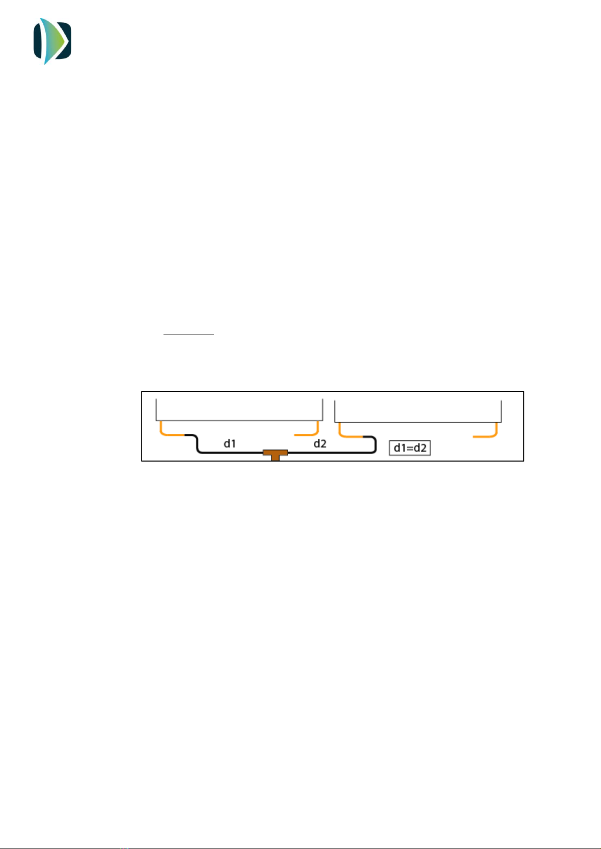
b. Distributor/ collector installation
Install a cooper tee to distribute and collect the refrigerant to/from the panels.
Its function is to ensure the homogeneous refrigerant flow in the whole panel installation.
The installer must weld a T connection of the following dimension:
-Gas line: 2 inlets 3/8 - 1 outlet 1/2
-Liquid line: 1 inlet 3/8 - 2 outlets 1/4
IMPORTANT: To ensure the same flow of refrigerant in every panel and consequently take
advantage of the evaporation surface entirely, you should install the same tube length
from the distributor to each panel. If a pipe is too long for the length require, it must be
rolled up.

INSTALLATION AND USER MANUAL
ECOHEAT TD
10 V0REV1EN0422
IMPORTANT: It is recommended to weld pipelines by oxyacetylene welding.
Welding is a critical step in the installation and to do it well ensures that the system will run
properly along its useful life.
Only expert staff should make this step by using proper tools and high-quality materials.

INSTALLATION AND USER MANUAL
ECOHEAT TD
11 V0REV1EN0422
c. Join refrigerant pipes to the Panels and Ecoheat
Panels are supplied with two nuts for the inlet and outlet connection. The inlet to each panel
is 1/4 inch diameter. The installer has to insert the nut into the copper pipe, flare the pipe
and then use the nut to fit it. Repeat the procedure with the outlet connection using 3/8 inch
copper pipe.
The Ecoheat has two service valves with threaded connections:
-Inlet: 1/2 inch
-Outlet: 3/8 inch
The installer has to insert the nut into the copper pipe, flare the pipe and then use the nut
to fit it.
d. Nitrogen test and cleaning procedure
In order to check the tightness, introduce nitrogen by using the pressure gauge already
installed into load ports.
CAUTION: Never exceed a nitrogen load greater than 10 bars.
Use leaking detector fluid at every welding and even in panel’s connections to verify the
absence of leaks.
e. Vacuum
Connect the vacuum pipe to the pressure gauge to carry out a vacuum of the whole
installation.
f. Coolant filling
Open the load ports to fill the circuit with the refrigerant loaded into the system.

INSTALLATION AND USER MANUAL
ECOHEAT TD
12 V0REV1EN0422
8. HIDRAULIC CONNECTION
The hydraulic connections are shown in the following scheme:
The installer must install the following components of the hydraulic circuit shown in the scheme.
-Cold water inlet (1)
-Ball valves (2)
-Pressure reducing valve (3)
-Non-return valve (4)
-Lined Filter Strainer (Y Type) (5)
-Drain (6)
-Safety valve (7)
-Expansion vessel (8)
-Check valve (9)
-Recirculation pump (10)
-DHW (11)
Once the hydraulic connections are made, vent the circuit to avoid the air inside the installation.

INSTALLATION AND USER MANUAL
ECOHEAT TD
13 V0REV1EN0422
9. ELECTRICAL CONNECTION
The power supply of the system is 230/1/50 Hz. The power supply line must be protected with
a 16 A circuit breaker. The electrical scheme is shown in the picture below:
PV: Photovoltaic connection
LPS: Low pressure switch
HPS: High pressure switch
NTC1: Water temperature probe
D: Display
R: Electrical heater
K: Compressor
230 VAC: Power supply

INSTALLATION AND USER MANUAL
ECOHEAT TD
14 V0REV1EN0422
10. COMISSIONING. CONTROLLER.
10.1. USER INTERFACE DESCRIPTIONE SCR IP TI
Symbol
Meaning when it lights
Compressor switched on
Defrost active
Fan switched on
Alarm active
Compressor working hours exceeded
Unit in ºC
Unit in ºF
Electric heater switched on
Stand by
INSTALLATION AND USER MANUAL
ECOHEAT TD
15 V0REV1EN0422
10.2. INSTALLATION- Switching on
After full installation of the water heater (power and water pipes connected) and after
the water heater tank is full of water, power can be turn ON.
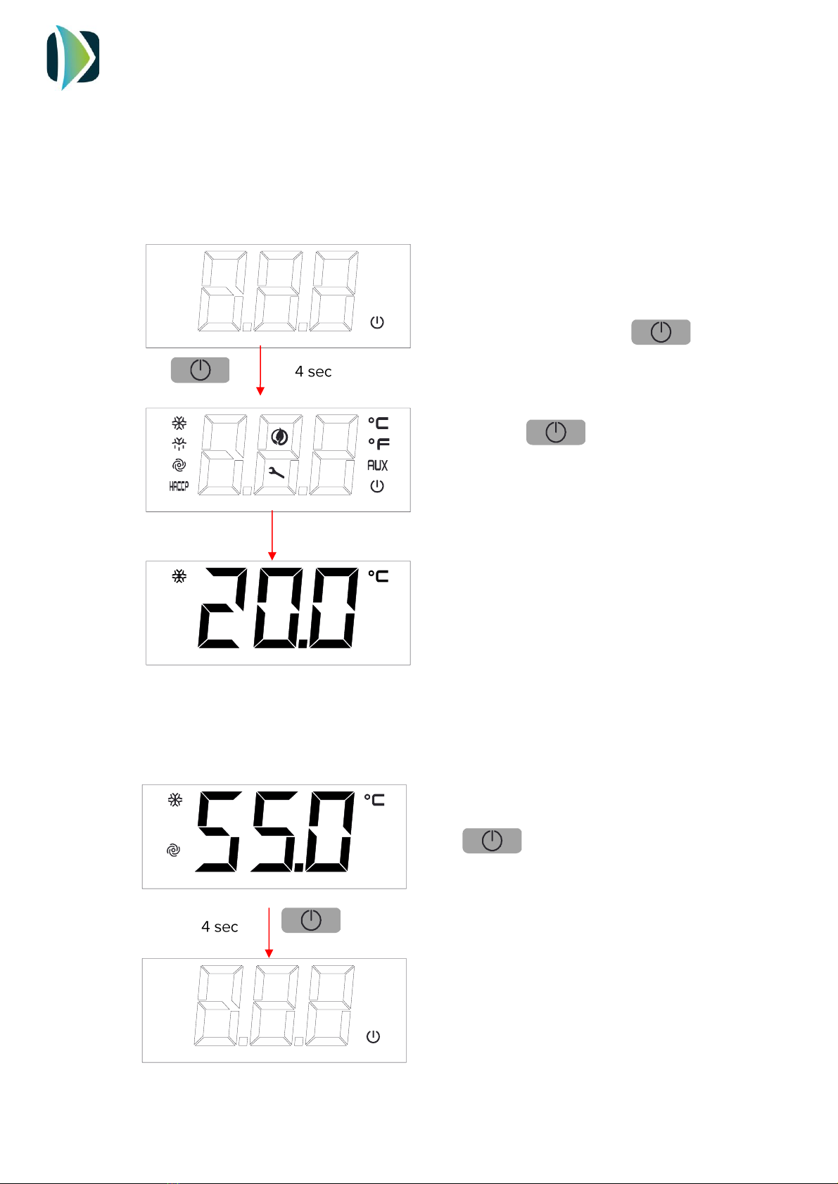
10.3. Switching OFF
1. After filling the tank of water, connect the
mains plug to the mains supply.
The screen will show the symbol
2. Hold the key for 4 seconds. The
display will show the icons.
3. The screen will show the water
temperature
To switch off the system, hold the
key for 4 seconds

INSTALLATION AND USER MANUAL
ECOHEAT TD
16 V0REV1EN0422
10.4. Unlocking the keypad
10.5. Displaying the operating mode
At first initial power ON, the product goes, by default, in Eco mode. By touching one time
the key, the controller will show the mode in operation in this moment.
When 30 have elapsed without the keys being
pressed, the display will show the ‘’ LOC’’ label
and the keypad will lock automatically
Touch any key until the screen shows UnL, to
unlock the keypad
ECO Mode: Heating only by heat pump technology
Auto Mode: Heating by heat pump and electric heater
only if the water temperature falls drastically
OverBoost Mode: Simultaneously heating by heat pump
and electrical heater to achieve the temperature setpoint
as quickly as possible
Defrost: Defrost cycle active
Photovoltaics/ Timer: Automatic working due to the
existence of surplus energy from PV installation or Off-
Peak Rate
Antilegionella: Automatic disinfection by thermal shock
INSTALLATION AND USER MANUAL
ECOHEAT TD
17 V0REV1EN0422
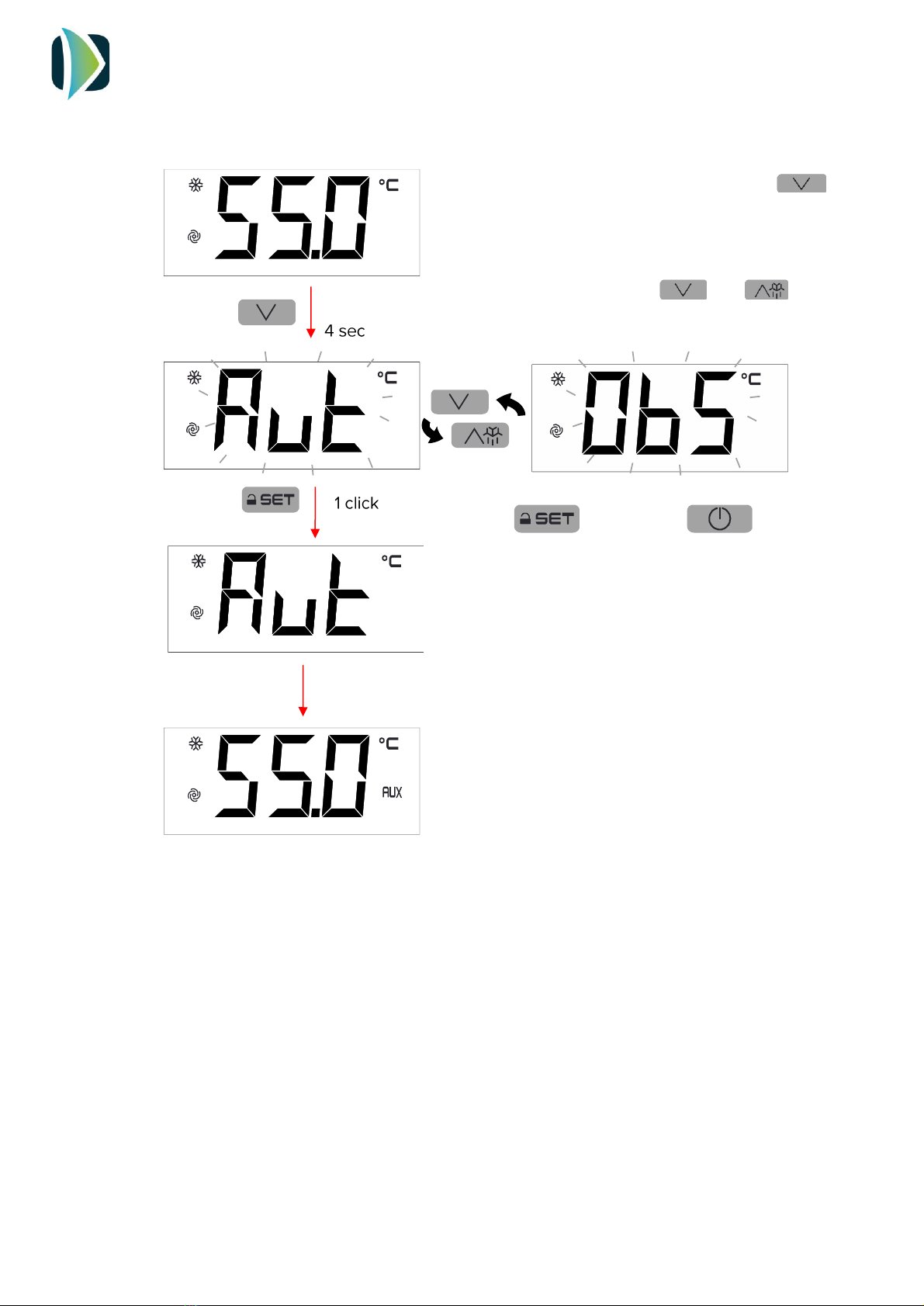
10.6. Changing operating mode
To change the operating mode, touch the
key for 4 seconds.
The screen will show blinking the selectable
operating modes. Use the and keys
to select the operating mode.
Touch to confirm or to cancel
The screen will show again the water
temperature
Table of contents
Other Climer Heater manuals


