CLIMET INSTRUMENTS CI-154 User manual

CI-154
LASER PARTICLE COUNTER
OPERATOR’S MANUAL
Revision 3.20 –December 28, 2015
CLIMET INSTRUMENTS
1320 West Colton Avenue, Redlands, CA 92374 Manual P/N 03015400
PHONE: (909) 793-2788 FAX: (909) 793-1738
www.climet.com

CI-154 User’s Manual
Page ii

CI-154 User’s Manual
Page iii
ADDENDUM
Portable Particle Counters
Security System Enhancements
ACCESS TO CLEAR DATA MENU BUTTON
Firmware version 3.20 has been created to enable more control over the availability
of the CLEAR DATA button depending on the security level of the user that is logged
in.
There are four levels of security available on the portable particle counters.
Analysts with Level 1 security can operate a portable particle counter to select ID’s
and acquire data. Level 1 users cannot print reports or clear data. Previous
firmware versions permit Level 2 or 3 users to print a report but they can also clear
data.
Starting with firmware version 3.20 it is possible to remove the ability for Level 2
and 3 users to clear data.
A special RS-232 command now exists, which a technician can send one time to the
counter. After the command has been received, the [CLEAR DATA] button will be
greyed out for Level 2 and 3 users and they will no longer be able to clear data.
This characteristic will be retained permanently by the counter unless it is cancelled
by another special RS-232 command.
Please contact Climet Instruments Co. or your Authorized Climet service provider
for further information.
BACKDOOR SUPERVISOR PASSWORD
Climet Instruments Co. and authorized Climet service providers are able to disclose
a secret supervisor password to enable a supervisor to gain access to their counter
if the password set by the supervisor has been forgotten. Starting with version
3.00, a program was developed that enables a temporary password to be
generated that is only good for one particular counter until its calibration date
changes. Starting with version 3.02, the backdoor password was changed so the old
universal one no longer works.
If the supervisor password is forgotten, please feel free to contact Climet or an
authorized Climet service provider. Please provide the firmware version number,
serial number and calibration date exactly as it is shown on the splash screen.
Please also provide the name, title and contact information for the person at your
company who is authorized to receive the temporary password.

CI-154 User’s Manual
Page iv

CI-154 User’s Manual
Page v
Table of contents
1. Introduction _______________________________________ 1
1.1 Caution ___________________________________________ 1
1.2 Notes ____________________________________________ 1
1.2.1 Laser diode life _________________________________________ 1
1.2.2 Calibration interval ______________________________________ 1
1.2.3 Patents _______________________________________________ 1
1.3 Unpacking and installation ____________________________ 2
1.3.1 Unpacking_____________________________________________ 2
1.3.2 Power requirements _____________________________________ 2
1.3.3 Safety ________________________________________________ 2
1.3.4 Handling ______________________________________________ 2
1.3.5 Cleaning ______________________________________________ 2
1.3.6 Storage_______________________________________________ 3
1.3.7 Packing for shipment ____________________________________ 3
1.4 Overview of CI-154 features __________________________ 3
1.5 Specifications ______________________________________7
2. Operation _________________________________________ 9
2.1 Getting familiar with the CI-154________________________ 9
2.1.1 The CI-154 chassis______________________________________ 9
2.1.2 The CI-154 user interface _______________________________ 10
2.2 Performing routine tasks with the CI-154 _______________ 11
2.2.1 How to take a sample___________________________________ 11
2.2.2 How to set an alarm level for particle count _________________ 11
2.2.3 How to set an alarm level for flow _________________________ 12
2.2.4 How to create and use a stored program ____________________ 12
2.2.5 Using stored programs on a USB jump drive _________________ 13
2.2.6 Using the clone feature via USB ___________________________ 14
2.2.7 How to create and use location IDs ________________________ 15
2.2.8 How to auto advance location IDs _________________________ 15
2.2.9 Using the clone feature via RS-232 ________________________ 17
2.2.10 How to print data ______________________________________ 17
2.2.11 How to view stored data on-screen ________________________ 18
2.2.12 How to copy stored data to the USB jump drive ______________ 19
2.2.13 How to download data to a computer ______________________ 19

CI-154 User’s Manual
Page vi
2.2.14 How to clear stored data ________________________________ 19
2.3 Changing paper____________________________________19
2.4 Battery operation __________________________________20
2.5 Sample settings ___________________________________ 20
2.5.1 Sample volume________________________________________ 20
2.5.2 Initial delay___________________________________________ 20
2.5.3 Sample delay _________________________________________ 21
2.5.4 Number of samples ____________________________________ 21
2.5.5 Auto-average _________________________________________ 22
2.6 Display modes_____________________________________ 22
2.6.1 Total versus Differential count mode _______________________ 22
2.6.2 Count versus concentration mode _________________________ 22
2.7 Printer settings ____________________________________23
2.7.1 Large font ____________________________________________ 23
2.7.2 End of sample printouts _________________________________ 23
2.7.3 Printing alarms only ____________________________________ 24
2.8 Setting alarms ____________________________________ 25
2.8.1 Setting alarm levels ____________________________________ 25
2.8.2 Beeper mode _________________________________________ 25
2.8.3 Alarm indicators on the display ___________________________ 26
2.8.4 Silencing the alarm_____________________________________ 26
2.9 Selecting channels to display _________________________ 26
2.10 Setting date and time _______________________________ 26
2.11 Using IDs ________________________________________ 26
2.11.1 Creating an ID ________________________________________ 27
2.11.2 Selecting an ID________________________________________ 27
2.11.3 Deleting an ID ________________________________________ 27
2.12 Using programs with IDs and settings __________________ 27
2.12.1 Programs in internal memory_____________________________ 27
2.13 Getting reports ____________________________________ 28
2.13.1 Accessing report screens ________________________________ 28
2.13.2 Settings _____________________________________________ 28
2.13.3 Selecting data to report _________________________________ 29
2.13.4 Printing all stored data __________________________________ 30
2.13.5 Printing alarm data_____________________________________ 31
2.13.6 Printing average data ___________________________________ 32
2.13.7 Printing an ISO 14644-1 (2015) report _____________________ 33
2.13.8 Printing an FS-209E report_______________________________ 34

CI-154 User’s Manual
Page vii
2.13.9 Printing a GMP 2008 report ______________________________ 36
2.14 Security__________________________________________ 38
2.14.1 Enabling security ______________________________________ 38
2.14.2 Add/Remove users _____________________________________ 39
2.14.3 Auto log off___________________________________________ 39
2.14.4 Lock unit_____________________________________________ 40
2.14.5 Unit ID ______________________________________________ 40
2.14.6 Altitude______________________________________________ 40
2.14.7 Cal Due______________________________________________ 40
3. Auxiliary connections _______________________________ 41
3.1 USB interface _____________________________________41
3.1.1 3.1.1 CSV file format ___________________________________ 41
3.2 RS-232 interface ___________________________________43
3.2.1 Controlling the CI-154 through the RS-232 interface __________ 43
3.3 Ethernet interface__________________________________44
3.3.1 Connection and Factory Settings __________________________ 44
3.3.2 The Configuration Utility. ________________________________ 44
3.3.3 Connecting using Telnet. ________________________________ 46
3.3.4 The RS-232 and telnet command list _______________________ 48
3.3.5 RS-232 and telnet output format __________________________ 54
3.3.6 MODBUS®: __________________________________________ 56
3.3.7 Status Bits Defined: ____________________________________ 62
3.3.8 Unit web server pages: _________________________________ 62
3.4 Alarm connector ___________________________________66
4. Theory of operation ________________________________ 67
4.1 How particles are detected ___________________________ 67
4.2 The systems of a particle counter______________________ 67
4.2.1 The airflow system _____________________________________ 68
4.2.2 The light source _______________________________________ 68
4.2.3 The optical system _____________________________________ 68
4.2.4 The electronic subsystems _______________________________ 69
5. Application guide __________________________________ 71
5.1 Using standard and optional accessories ________________ 71
5.1.1 Using the Isokinetic probe _______________________________ 71
5.1.2 Using the zero count filter _______________________________ 71
5.1.3 Using high pressure diffusers _____________________________ 71

CI-154 User’s Manual
Page viii
5.2 Monitoring _______________________________________ 72
5.2.1 The where, why, and how of monitoring ____________________ 72
5.2.2 5.2.2 Monitoring hot air sources __________________________ 73
6. Service and maintenance ____________________________ 75
6.1 User maintenance __________________________________75
6.1.1 Battery replacement____________________________________ 75
6.1.2 Fuse replacement ______________________________________ 75
6.1.3 Long term storage _____________________________________ 76
6.2 Analyzing counting irregularities ______________________ 76
6.2.1 High counts, limited to the 0.3 m channel __________________ 76
6.2.2 Similar counts on two or more channels ____________________ 76
6.3 Low laser power ___________________________________ 77
6.4 Low flow rate _____________________________________ 77
6.5 Calibration service _________________________________77
7. Frequently asked questions __________________________ 79
8. Appendix ________________________________________ 83
8.1 Legacy Modbus coils ________________________________ 83
8.2 Legacy Modbus® Diagnostic Functions__________________ 83
8.2.1 Example Diagnostic Commands: __________________________ 84
EU Declaration of Conformity _____________________________ 87

CI-154 User’s Manual
Page ix
FRONT VIEW OF CI-154

CI-154 User’s Manual
Page x
REAR PANEL OF CI-154

CI-154 User’s Manual
Page 1
1. Introduction
1.1 Caution
This is a Class 1 Laser Device as shipped from the factory. No laser radiation from
the laser diode is accessible by the user.
Use of controls or adjustments or performance of procedures other than those
specified herein may result in hazardous radiation exposure.1
1Federal Register 21 CFR 1040.10 h iv J
1.2 Notes
1.2.1 Laser diode life
Climet’s sensor design offers very efficient light collection, which allows laser diodes
used in Climet particle counters to be set conservatively, effectively extending the
life of the laser diode. The life of the laser diode is affected by temperature, as well
as number of hours of operation. Laser diode failures are widely scattered over time,
rather than tightly clustered. Experience with this laser diode in Climet particle
counters indicates that it can be expected to provide years of service when the
counter is used within its specifications.
To insure proper performance, the CI-154 should be operated in a well-ventilated
area. Operating the instrument in areas with elevated temperatures for extended
periods of time may shorten the life of the laser diode.
1.2.2 Calibration interval
The CI-154 is based on technology proven on a variety of reliable, stable
instruments, and can be expected to maintain its calibration within specified
tolerances for several years. However, in accordance with ANSI Z540 and ISO
10012, it is recommended that the instrument be calibrated annually to insure the
integrity of the data collected with the instrument and to meet monitoring or testing
requirements of the application in which the particle counter is used.
1.2.3 Patents
The CI-154 is protected by one or more of the following U. S. or Japanese patents:
US RE 37,353E
5,515,164
5,825,487
5,870,190
3327393 (Japan)
7,733,486

CI-154 User’s Manual
Page 2
1.3 Unpacking and installation
1.3.1 Unpacking
The CI-154 is packed in a specially designed shipping container, which has been
tested to withstand normal amounts of shock and vibration in accordance with the
National Safe Transit Association (NSTA). Save the shipping box to minimize the
chance of shipping damage when the instrument needs to be returned for calibration
or repair.
After unpacking the CI-154, inspect the instrument for any signs of damage. If there
is any damage, you should file a claim with the shipping company and contact
Climet Instruments.
1.3.2 Power requirements
The CI-154 is equipped with a universal input AC power supply that supports inputs
from 100–240 VAC, 47–63 Hz.
1.3.3 Safety
The operator or maintenance person should not remove any of the covers on the
Climet particle counter except in accordance with the procedures provided by the
manufacturer. Unauthorized disassembly can result in exposure to laser light.
The CI-154 contains a 9.6 Volt, maintenance-free, rechargeable nickel metal hydride
battery, which can be replaced by the user.
The CI-154 comes with a three prong, grounded AC power cord. Failure to make a
proper earth ground connection may result in a shock hazard and may damage the
instrument. Do not use a two-to-three prong adapter unless its ground connection
has been properly connected to a good ground on the wall socket.
1.3.4 Handling
Although the particle counter has a rugged stainless steel enclosure, the operator
should exercise proper care when carrying or transporting the unit. Hard blows to
the exterior of the instrument may cause damage. Particular care needs to be
exercised to prevent impacts to the display which may result in cracking the
relatively thin touch screen glass.
1.3.5 Cleaning
The CI-154’s stainless steel enclosure and overlay are resistant to most cleaning
chemicals. When cleaning the unit, follow these precautions:
Turn the unit off and remove the power cord.
Cap the inlet or attach a sample probe (with the sample head either
capped, pointed down, or away) to prevent fluid from entering the
unit.
Cover the electrical connectors with the caps provided.
Wipe the surface of the unit with a cloth or wipe, dampened with
cleaning solutions. Do not allow the cleaning solution to saturate the
printer mechanism.

CI-154 User’s Manual
Page 3
When cleaning agents are sprayed near the instrument, be sure that
the instrument is off, and that the inlet is capped.
1.3.6 Storage
If the CI-154 is to be stored for more than one month without use, the battery
should be disconnected to prevent damage to the battery from a deep discharge.
Please refer to the Service and Maintenance section of this manual for instructions
on long term storage.
1.3.7 Packing for shipment
The packing container used for shipping the CI-154 has been tested according to the
standards of the National Safe Transit Association. For this reason, it is
recommended that the original packing container be saved for reuse if it has no
obvious damage. The packing container consists of an outer double-walled
cardboard box, two foam inserts, and an internal cardboard box used to hold
accessories. This internal box also serves the important function of tightening the
foam inserts against the CI-154. If for any reason the internal box cannot be used,
insert additional packing material to fill the empty space and tighten the foam
inserts against the CI-154.
NOTE:
When returning the CI-154 for servicing, keep the
accessories in a safe place at your facility. No
accessories are needed during calibration or repair.
If the original shipping carton was discarded, select a cardboard box large enough
that at least 3 inches of heavy bubble wrap can be placed on all sides of the
instrument. Any extensions (handle, feet) should be especially well protected,
because the impact is amplified if the carton is dropped on a part that extends out
from the rest of the chassis. Avoid the use of loose packing materials such as
peanuts, because they shift and leave one side of the instrument unprotected.
Shipping companies do not accept responsibility for damage when the instrument is
poorly packed.
1.4 Overview of CI-154 features
The CI-154 (Climet Instruments 154) is a laser diode based aerosol particle counter
that monitors particles in four size ranges.: 0.3, 0.5, 1 and 5 m. It is fully self-
contained, operating on battery power or AC power for sampling convenience. It has
a stainless steel enclosure that makes it suitable for applications requiring a sterile
wipe-down.
The CI-154 has a sample flow rate of 1 cubic foot per minute (1 CFM) or 28.3 liters
per minute (28.3 LPM), requiring 35.3 minutes to take a full 1 cubic meter sample.
The built-in battery can provide 5.5–6.5 hours of continuous sampling on a single
charge. The CI-154 interfaces with the user through a color LCD touch screen. It
comes with a thermal printer, and uses patented optical and flow systems with
automatic flow control. The sample air is filtered before being exhausted through the
rear panel. When used for special applications where the air sample must be
exhausted out of the area, a fitting can be attached to the exhaust port to allow
tubing to be connected to the exhaust.

CI-154 User’s Manual
Page 4
Counts may be displayed and printed in a variety of formats, including Total Count,
Differential Count, Concentration per Cubic Foot, Concentration per Cubic Liter, and
Concentration per Cubic Meter. Alarm settings are available for each particle
channel, including a Beep On Count setting that is useful in filter scanning
applications. In addition to the particle channel alarms, alarms can be set for the
sample flow rate.
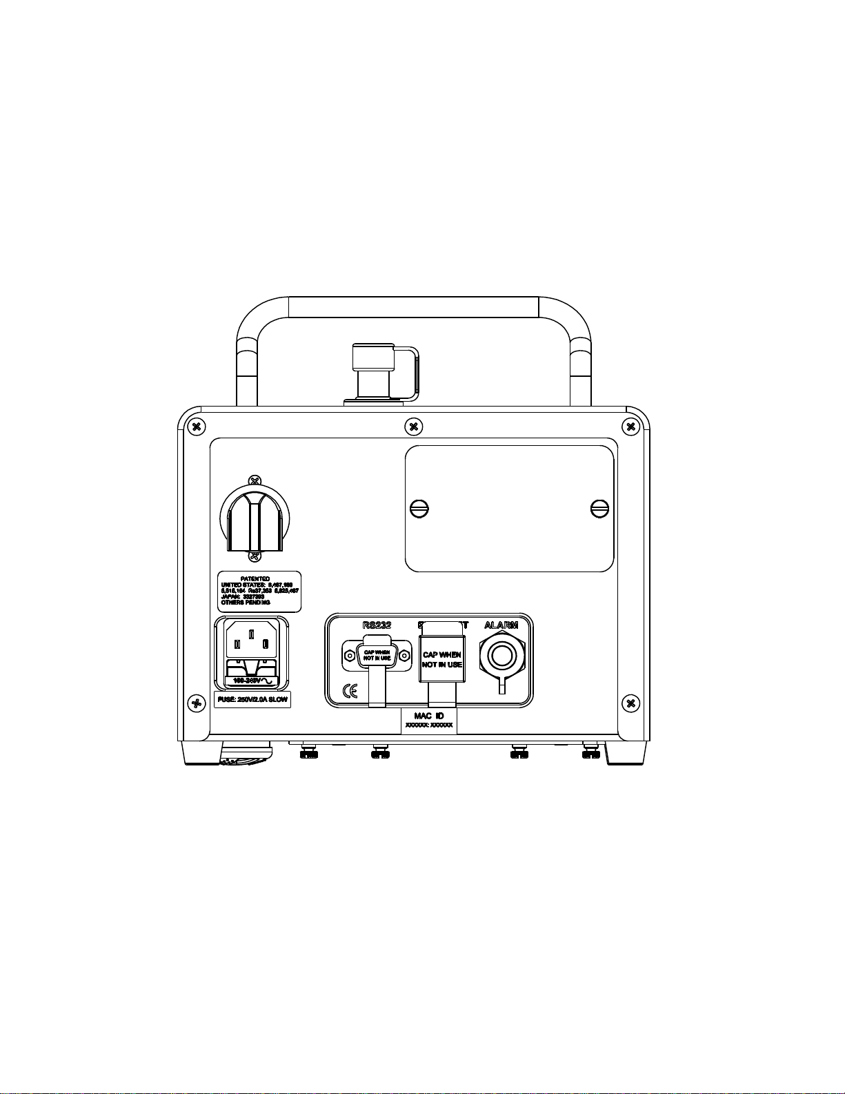
Up to 3,000 samples can be stored in the internal memory, and can be transferred
as a comma delimited ASCII file through the RS-232 serial port or Ethernet port to a
computer. They can be easily transferred to common spreadsheets. All samples are
date and time stamped. Once the data is taken, the user can view or print a variety
of reports, such as Alarm Violations, Averages, ISO 14644-1, GMP, or Federal
Standard 209E.
A USB port is available on the front panel for connecting a USB jump drive. The
samples stored in the internal memory can be copied to a file on the drive. The data
in the file is comma separated text with a check code at the end for verifying data
integrity. User programs containing location ID’s and settings can also be read out
and written to the drive. The USB clone feature enables settings to be duplicated
from one unit to another. The USB menu system appears when the drive is inserted.
An alphanumeric keypad is provided on the touch screen for entering location IDs.
Each sample may be assigned to a location ID when it is acquired. A numeric keypad
is provided on the touch screen for entering sample volumes, delays, alarms, and
other numerically set parameters. A distinct initial delay may be set independent of
subsequent delays between samples. This feature gives the operator extra time to
clear the area before the particle counter begins sampling. Other sample settings
program the CI-154 to take a certain number of samples, then stop, or to take
samples once every given time period. Averages can be automatically printed at the
end of a given number of samples. The blower (pump) is turned off during long
delays to conserve battery power.
Once all of the settings are determined, they may be saved as a program using a
name determined by the user. Up to 100 location IDs are also saved with the
program. This enables the user to recall a set of locations and sample settings for a
given test situation. Up to 30 programs with 100 IDs each may be saved in the
internal memory. Reports are grouped by program names. Therefore, the user can
assign programs named for certain areas for which separate reports are required.
The CI-154 has a user authentication and password protection feature that can be
enabled. This feature allows certain permissions to be granted users depending on
their access level. User names are printed on all reports and records when this
feature is enabled. Users are authenticated by their personal private passwords. A
supervisor level is provided for administering users. Up to 20 users may be defined
with one of four access levels. Access levels are applied to the USB functions as well.
A user definable unit ID is also provided that likewise prints on all records and
reports when this feature is enabled.
The patented particle sensor used in the CI-154 operates on the light scattering
principle. It uses a laser diode as the light source, and an elliptical mirror collection
system. The light scattered by particles and collected by the elliptical mirror is
focused onto a solid-state photo detector, which converts the light energy into
electrical current. The highly efficient optical system and detection electronics
provide the means for this instrument to correctly size and count particles, based on
NIST traceable standards.

CI-154 User’s Manual
Page 5
The CI-154 has been designed to provide rugged, long-term performance. The laser
diode light source is controlled with a closed loop drive circuit to maintain a constant
intensity over time and temperature variations. The status of the laser power is
monitored and displayed as OK or LOW on the main screen. If the laser power falls
below 90%, a LOW status is displayed. The rugged laser diode light source, along
with the stability of the optics and detection electronics, provides for overall
consistent performance. Given the stability of the laser diode control circuitry and
amplifier circuits, the CI-154 requires routine calibration only once every 12 months.

CI-154 User’s Manual
Page 6

CI-154 User’s Manual
Page 7
1.5 Specifications
Illumination source:
Laser diode, 50 mW
Light Collection Optics:
Elliptical mirror
Detection:
Silicon photo diode
Size sensitivity:
0.30 m
Particle channel sizes:
Four sizes: 0.3, 0.5, 1.0, 5.0 m
Size resolution:
Meets requirements of ISO 21501-4 - 10% typical
Concentration limit:
1.0 x 10⁶particles per cubic foot (10% coincidence)
(35.3 x 10⁶particles per cubic meter)
Sample flow rate:
1.00 cubic feet per minute
(0.028 cubic meter or 28.3 liters per minute)
Flow rate control:
Electronic, automatic closed loop
Sample tube extension:
3/8” (9.525 mm) I.D., up to 20 ft. (6.1 meters) max. length
Max. False Count Rate:
7.1 per CM >0.3 µm (95% UCL) per ISO 21501-4
(1 count per five minutes)
Battery:
Replaceable 9.6 Volts, 12.6 Amp hour Nickel Metal Hydride
Battery operation time: 5.5 to 6.5 hours continuous operation
Time to charge battery:3.5 to 4.0 hours
Display:
TFT Color LCD, ¼ VGA touch screen
Printer:
Thermal Dot Matrix
Memory:
3,000 samples, date and time stamped
Unit ID:
User selectable
User ID:
Up to 20 users, besides supervisor, with password
Security:
Four security levels with user authentication
Location ID:
Up to 100 per program; 16 characters long.
Program:
Up to 30 user-defined and named, containing IDs and settings.
Input/Output (RS-232):
ASCII command set, CSV data output with check code
+5 VDC @ 400 mA provided on pin 9
Input/Output (Ethernet)
10/100Base-T, half or full duplex (auto sensing), http web
server, Ethernet Modbus®server and TELNET server
Input/Output (USB)
Transfer of stored data memory to jump drive
Transfer of user-defined programs to/from jump drive
Transfer of unit settings to/from unit via jump drive
Beep On Count:
0.3 m and greater.
Audible alarm:
Built-in
Alarm output:
Dry contacts, normally open or closed via alarm connector.
Connector also has +12VDC @ 250mA.
Alarm limits:
Programmable for all particle channels and flow.
Dimensions:
H-W-D: 8.65 x 8.5 x 9.5 inches (21.97 X 21.6 X 24.1 cm)
Weight:
11.0 lb (4.99 Kg) without battery
14.25 lb (6.46 Kg) with battery
Power:
Auto switching: 100–240 VAC, 47/63 Hz, 90VA max
Fuses:
two 5 X 20 mm, 250V/2.0 Amp Slow
Operating range:
0–36º C, 10–90% RH, non-condensing
Calibration:
Factory Prime Calibration complying with ISO 21501-4.
NIST traceable using CalPro 2.00 (or later) software program.
Calibration frequency:
Recommended every 12 months.
Gas compatibility:
Air, nitrogen; consult factory regarding other gases.

CI-154 User’s Manual
Page 8

CI-154 User’s Manual
Page 9
2. Operation
2.1 Getting familiar with the CI-154
NOTE:
The CI-154 is equipped with security features that
restrict access to controls depending on the security
level of a logged on user. The security features are
not enabled when the CI-154 is initially shipped from
the factory. It is recommended that the user become
familiar with the basic operation of the CI-154 before
enabling the security features.
2.1.1 The CI-154 chassis
The CI-154 has a brushed, stainless steel chassis to maintain a clean appearance
while providing the preferred covering for equipment that may be routinely exposed
to harsh, disinfectant solutions.
An overlay covers the LCD touch screen and power switch, protecting them during
cleaning. The USB connector is located on the front. A captive cover protects the
connector when not in use.
Below the power button is a green LED. The LED flashes when the battery is fully
charged. When the battery is being charged, the light is solid green. When the unit
is turned on, the charging circuit is turned off and the LED is off. The battery is
located in the base of the unit and is accessed through a door on the bottom of the
instrument.
In the upper right corner of the rear panel is a cover for the printer paper
compartment. It is held on by two slotted thumbscrews, which are easily removed
by hand or screwdriver.
There is an exhaust port at the back of the unit. Located at the top left corner, a
white, screw-on cover has the exhaust blowing downwards. This port cover helps
protect the instrument during applications of disinfectant solutions, and does not
need to be removed during normal operation. The cover can be screwed off and
replaced with the external exhaust fitting (an accessory included with the unit,
Climet part number 01246000) that is used in certain applications to exhaust the
sample air out of the area through ½ inch ID tubing.
Connectors are located on the back, including a standard DB-9 RS-232 connector,
an Ethernet connector, and one round connector for an alarm output. The
connectors have captive covers used to protect the ports when not in use.
The AC power entry module is located on the rear panel. It connects to a universal
power supply that can operate on AC power ranging from 100 VAC to 240 VAC. One
of three power cords are supplied, depending on the destination: U.S., DIN
(European) or British.

CI-154 User’s Manual
Page 10
2.1.2 The CI-154 user interface
The CI-154 uses a color touch screen display that allows the user to control the
operation of the CI-154 through soft keys on the display’s touch screen. The unit is
turned on by a momentary switch to the right of the display. There will be a slight
pause—about four seconds—before the opening screen appears.
The opening screen shows the last date the instrument was calibrated, and the next
calibration due date. It also displays the serial number of the instrument and the
currently installed firmware version. After a couple of seconds, the opening screen is
replaced by the main data screen (or the log-in screen if the security feature is
enabled).
The main screen displays data being collected by the particle counter while the unit
is in sample mode. Along the bottom of the screen are a series of soft keys that
allow the user to start sampling, assign an ID to the sample, print a report of the
samples, load pre-configured sampling settings, or enter settings.
Other menus may be accessed from these keys to further control the operation of
the CI-154. Those familiar with computers and particle counters may find that they
can readily figure out how to operate the CI-154 without consulting the manual.
Many of the keys change from green to yellow, or from yellow to green when
pressed. A feature is enabled or selected when the key is green, and disabled or
deselected when the key is yellow.
Touch screen displays offer greater convenience than membrane keys, but they do
have their own peculiarities. If pressed slowly and gently, the wrong key may
respond occasionally. To avoid this, key presses should be firm and without
hesitation.
CAUTION:
Do not use a pen, stylus, or other hard object
to press keys. This could damage the touch
screen, and is not covered by the warranty.
In addition to the soft keys along the bottom of the main screen, there is a colored
box displaying the status of the sample. This box is normally green with the word OK
in the center of the box. If alarms are set, the box will turn red in response to an
alarm violation, and the channel that violated the alarm level will be highlighted in
red. Pressing this status box will reset the alarm for the current sample. The box will
also turn red if low laser power or low battery is detected.
NOTE:
Any samples taken when low laser power is detected
will not be printed or stored in memory.
Just below the status box is the word NETWORK with 2 small rectangles beneath it.
The left side rectangle will change from black to yellow if an Ethernet cable is
plugged into the Ethernet receptacle on the rear panel and a successful link is
established. The right hand rectangle will flash green when there is network traffic,
not necessarily with the unit itself.
Table of contents
Popular Laboratory Equipment manuals by other brands

Amersham
Amersham Frac-950 user manual

Genetix
Genetix QPix Robot Manual

Watts
Watts PURE WATER PWUV Series Installation, operation and maintenance manual

Sartorius stedim
Sartorius stedim Microsart Combi.jet 16847-CJ manual

Thermo Scientific
Thermo Scientific Nicolet Summit user guide

Woodley
Woodley Clinispin Horizon 853VES Operator's manual