Climma 210705 User manual

Service manual
DIGITAL CONTROL PANEL MK2
Rev. 210705
Veco SpA
Service manual MK2–Pagina 2 / 9
Table of contents
1. Introduction......................................................................................................................................................................................... 3
1.1. Safety.......................................................................................................................................................................................... 3
1.2. Release check......................................................................................................................................................................... 3
2. Configuration of control panel MK2.......................................................................................................................................... 4
2.1. Configuration ........................................................................................................................................................................... 4
3. Service parameters .........................................................................................................................................................................5
3.1. Password for service parameters ................................................................................................................................... 5
3.2. Service parameters list........................................................................................................................................................ 5
3.3. Parameters for the temperature control .......................................................................................................................6
3.4. Parameters for the fan speed control............................................................................................................................ 6
3.5. Parameters for the unit management ...........................................................................................................................7
4. Error messages and alarms ........................................................................................................................................................ 8
4.1. Display blank ........................................................................................................................................................................... 8
4.2. Display shows the COOL led blinking (only for Fan coil units)........................................................................... 8
4.3. Display shows nPr................................................................................................................................................................ 8
4.4. Display shows err (only for Fan coil units) .................................................................................................................8
4.5. Display shows nA (only for Compact e Split units)..................................................................................................8
4.6. 7 Display shows HP (only for Compact e Split units) .............................................................................................8
4.7. 7 Display shows C.FL ..........................................................................................................................................................8
4.8. 7 Display shows nor (only for Fan coil units) .............................................................................................................8
5. Firmware update .............................................................................................................................................................................. 9
5.1. Digital MK2 panel update ...................................................................................................................................................9
5.2. Firmware version ...................................................................................................................................................................9

Veco SpA
Service manual MK2–Pagina 3 / 9
1. Introduction
1.1. Safety
Injuries or accidents caused by failure to comply with the recommendations of this manual are solely the
responsibility of the unit operator.
Basic Rules for Safe Operation:
• do not touch the unit with moist or wet hands or feet;
• never operate the unit while barefoot;
• before installation and maintenance operations, disconnect the unit from the power supply. failure to
comply may result in injury or death;
• installation and maintenance of this system can be hazardous due to system working pressure and
electrical components. Only a Climma certified service centre should install and maintain the system; • to
minimize the hazard of electrical shock and personal injury, this component must be effectively grounded;
• during installation and maintenance follow safety codes, wear safety glasses and work gloves.
1.2. Release check
At power-on of the unit check the information appearing on the control panel display
The example shows a digital panel MK2 at power up connected to a unit Fan coil.
In this MK2 the firmware release is v6.0. The other information is related to the unit connected to the panel.
The latest fimware version in 2021 is v.6.1. The digital panel MK2 from the v5.3 del 2011 is compatible with
the fan coil control MV8 and the MK3 control for units Compact and Split.
In order to upgrade the firmware of the digital panel MK2 see chapter 5.1.
Veco SpA
Service manual MK2–Pagina 4 / 9
2. Configuration of control panel MK2
2.1. Configuration
The digital panel MK2 is automatically configured as it is connected to the air-conditioner and powered. For
the options accessible for the user, see the user manual.
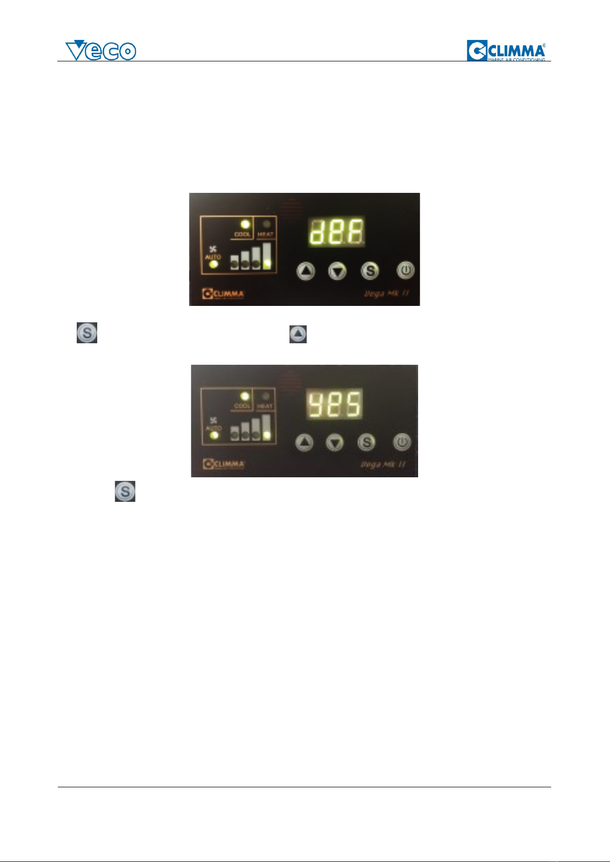
The user parameter which can be useful in case of mulfunctioning or abnormal behavior is the parameter dEF
which permits to reset to default all the parameters including the hidden ones.
deF is the parameter which all the parameters to the original values to factory values. To proceed press the
key . . The display prompts NO. Press the key to change to Yes.
Press again to reset to default. Also, the set point value is reset to the original factory value.
IMPORTANT: the system has a very limited time-off time (5 seconds) to prevent inadvertent setting errors.
This means that the changes must take place quickly, otherwise the screen will return to normal operating
mode and the procedure for accessing the parameter changes will have to be repeated.
Veco SpA
Service manual MK2–Pagina 5 / 9
3. Service parameters
3.1. Password for service parameters
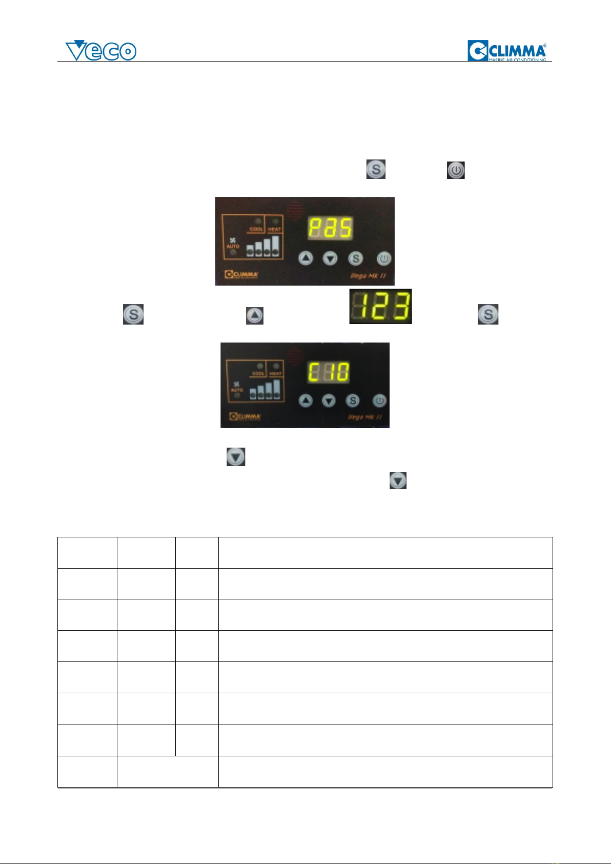
With the panel ON and the unit in OFF, press for 5 seconds the key and the key . The display
prompts
Press the key and then with the key reach the number . Confirm with . The
display prompts.
Browse the parameters with the key keeping in mind that the very limited time-off (5 seconds)
Important note: when the display promts C10 you can use ONLY the key stops the programming mode.
3.2. Service parameters list
parameter
name
default
description
C10
DIFF
1
sets the differential value in °C/F
C20
PAR
2
sets the parameter PAR used for the fan speed change. PAR+DIFF +/-
set-point is the temperature that starts the speed change
C30
upper limit
2
value in °C/F that added to the set point determines the change from
heat to cool mode when the system is running in A - auto mode
C40
lower limit
2
value in °C/F that subtracted from the set point determines the change
from cool to heat mode when the system is running in A - auto mode
C50
setpoint
unattended
5
value in °C/F of the inbcrease (Cool mode) or decrease (Heat mode) of
the set point for the mode U UNATTENDED
C60
timer
dehumidify
30
minutes of functioning (every 6 hours) of the unit in d - Dehumidify
mode
C70
not used

Veco SpA
Service manual MK2–Pagina 6 / 9
C80
not used
C90
network
address
1
Modbus address
C95
offset
external
probe
Off set of the temperture read by the external optional probe
C96
offset
internal
probe
4,3
Off set of the temperture read by the internal probe
tst
test
/
automatic test procedures
ti.H
Timer high
/
shows the first (left) 3 digits of the hour counter
ti.L
Timer low
/
shows the last (right) 3 digits (units) of the hour counter
Bdr
Baud rate
1
1=9.600 ; 2=19.200 ; 3=38.400
3.3. Parameters for the temperature control
C10 determines the differential. The differential is the value in ° C which, added or subtracted from the set-
point value, switches the air conditioner off or on. Increasing the differential increases the fluctuation of the
room temperature, because the air conditioner will perform longer cycles both in operation and in standstill.
C30 - C40 when the air conditioner is operating in A - automatic mode, the choice between Cool mode and
Heat mode is made by comparing the measured room temperature with the value set by the set-point. This
occurs when the air conditioner is switched on and is determined by the differential. If at the time of power-up
the room temperature is higher than the set-point value + the differential, the air conditioner starts in Cool
mode. If, instead, the room temperature is lower than the set-point minus the differential, then the air
conditioner starts in Heat mode. Parameters C30 and C40 becomes active once the air conditioner is already
working. To prevent particular conditions from changing the operating mode (from Cool to Heat) due to a small
temperature difference, the values of C30 and C40 are by default 2 and can be increased if necessary to avoid
oscillations of the air conditioner.
C95 allows you to intervene on the temperature detected by the external probe (if installed)
C96 the internal probe is incorporated in the MK2 panel. The area where the probe is installed undergoes a
progressive heating in the first 5 minutes from switching on. The heating is automatically compensated by
the panel with the value of 4.3 ° C at each power-up. Once powered, the temperature value remains correct.
If the panel is disconnected for a short time, the temperature read will be slightly higher because the
correction intervenes gradually in the first 5 minutes.
3.4. Parameters for the fan speed control
C20 - the PAR parameter determines the behavior of the fan when the room temperature approaches the set
point value and the fan operating mode is A-automatic. The PAR value is added to the value of the
differential C10 to determine the temperature at which the fan begins to reduce the speed. Example: set
point = 22 ° C, C10 = 1 e. C20 = 2. The reduction of the speed in the cooling cycle (cool) starts at 22 + 1 + 2
= 25 ° C.
The PAR value also determines the temperature range in which the fan passes from maximum to minimum
speed. Then continuing the same example, the fan speed changes from v8 to v7 at 24.9 ° C and gradually
decreases until it reaches v1 at 23 ° C. The air conditioner will continue to operate with the fan at minimum
until the set-point value is reached. When the set point is reached, the air conditioner will stop cooling. In the
heating cycle the behavior is the same but of course the set point is reached with an increase in
temperature.

Veco SpA
Service manual MK2–Pagina 7 / 9
.
3.5. Parameters for the unit management
–automatic test procedure. Confirming with the display promts the first option which is OFF.
Pressing the option is ALL, then the single tests from t1 to t5.
The following table shows the description of the tests according to the type of air conditioner unit to which the
MK2 panel is connected.
All includes the tests from t1 to t5 which are performed in sequence.
display
Unit Fan coil MV8
t1
b.L.e
powers the water valve
t2
.F.4
changes in sequence the fan speed (every 20 seconds). F4>F3>F2>F1>F4…..
t3
H.Y.d
Runs the fan at v3 + water valve
t4
E.L.t
Runs the fan at v3 + electric heater
t5
…---
Lits all the display leds (dots and segments) in sequence
display
Unit Compact and Split MK3
t1
.F.4
changes in sequence the fan speed (every 20 seconds). F4>F3>F2>F1>F4…..
t2
t.P.
Runs the sea water pump for 5 minutes
t3
t.C.
Runs the fan at v3, sea water pump and compressor for 5 minutes
t4
t.H.
On/OFF 3 times the reverse cycle valve/electric resistor (1 second). Then runs the fan
at v3 and powerrs again the reverse cycle valve/electric resistor for 5 minutes
t5
…---
Lits all the display leds (dots and segments) in sequence
To stop the test Test press the key which stops the test procedure and starts the unit.
ti.H –Hour counter = ti.H corresponds to thousands
ti.L -. Hour counter = ti.L corresponds to units.
The timer rsolution is 1 hour.
EXAMPLE: if ti.H = 3; ti.L = 245, the total functioning hours are 3,245.
bdr -communication speed of the Modbus network.
1=9.600; 2=19.200 ; 3=38.400
The default value is 1.

Veco SpA
Service manual MK2–Pagina 8 / 9
4. Error messages and alarms
4.1. Display blank
Check the power supply to the air conditioner control. Check that the plug of the connection cable is correctly
inserted both on the air conditioner control side and on the panel side.
If the unit PCB is powered correctly (lights on) and the cable is intact and inserted correctly, call the customer
service for a thorough check.
4.2. Display shows the COOL led blinking (only for Fan coil units)
The thermostat requires cooling but the chiller circuit has not reached the temperature required for cooling.
Also check that the water temperature sensor is correctly installed.
4.3. Display shows nPr
The air conditioner control is not set correctly. Check and correctly adjust the setting of the air conditioner
control dip switches following the instructions in the specific manual.
4.4. Display shows err (only for Fan coil units)
The water temperature sensor of the chiller circuit is not connected or is broken. Check the sensor.
4.5. Display shows nA (only for Compact e Split units)
The room temperature is below the set point value but the air conditioner does not allow heating. The air
conditioner control is set to CO (cool only). Check whether the air conditioner is actually equipped with a
reverse cycle or an electric heating element.
4.6. 7Display shows HP (only for Compact e Split units)
At the fourth safety intervention (high pressure switch) the word HP appears and the system stops.
The panel must be turned off and on again (with the ON / OFF button or from the remote control) to cancel
the alarm signal and restart the unit. See Compact and Split manual.
4.7. 7Display shows C.FL
The C.FL inscription invites the user to clean the air conditioner air filter (2500 hours of operation). To reset:
with panel ON press then until the display shows
Press the key The display prompts NO. Press the key to change to Yes. Press again to reset
the timer and cancel the C.F warning.
4.8. 7Display shows nor (only for Fan coil units)
In d-DEHUMIDIFY mode, the water of the chiller circuit has a temperature higher than 25°C.
Veco SpA
Service manual MK2–Pagina 9 / 9
5. Firmware update
5.1. Digital MK2 panel update
The firmware update of the MK digital panel is possible only in Veco factory.
5.2. Firmware version
The following table shows the latest firmware versions:
VERSION
DATE
CHARACTERISTICS
5.0
2009
PWM COMPATIBLE
5.1
2010
5.2
2010
ANTIFREEZE OPTION FOR COMPACT QUATTRO CONTROL
5.3
2011
MK3 COMPATIBLE
5.4
2011
5.5
2012
5.6
2012
INCREASED ELECTRONIC NOISE TOLERANCE AND UNIT
CONTROL PAIRING
5.7
2012
5.8
2013
ADDITIONAL THERMAL PROTECTION FOR PWM
5.9
2014
CUSTOM VERSION
6.0
2017
SET POINT DEFAULT AT 22°C
6.1
2021
MODIFIED REMOTE ON/OFF FOR MK3
Table of contents
Other Climma Control Panel manuals


