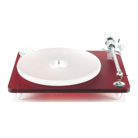
Clinton BASIS AUDIO 2800 Series User manual

BASIS AUDIO, INC.
2800 SIGNATURE SERIES TURNTABLE
USER’S GUIDE
26 Clinton Drive, Unit 116, Hollis, NH 03049 ▪ 603-889-4776 ▪www.basisaudio.com

2
INTRODUCTION
Thank you for purchasing the BASIS AUDIO 2800 Signature Series turntable. We are
confident that you will come to view your decision to use a BASIS turntable as one of the
most musically rewarding equipment choices in your audio experience.
The incredible precision of the BASIS bearing and platter system will allow you to feel
the emotion of the music’s natural flow. The unequaled effectiveness of the BASIS fluid-
damped suspension will open up your system’s soundstage, letting you hear low-level
details such as echoes deep in the sound field more clearly than you have experienced
before. Each instrument’s natural timbre will be portrayed with uncanny realism, and the
entire presentation will be without the exaggeration and artificial air that the resonances
of lesser designs create. Our goal at BASIS is that this effortlessness and realism allow
you to relax and appreciate the music more than you ever have before.
To realize the potential of your new turntable, and to prevent any damage which would
delay your enjoyment, please carefully read these instructions before attempting to
assemble your 2800. A 2200 Set-up DVD is also provided to show you a very similar
set-up process, and a link to the video can be found at https://www.basisaudio.com/2200
UNPACKING AND SETTING UP YOUR 2800 TURNTABLE
NOTE: You will find some white cotton gloves packed with your turntable. You may
wish to use the gloves while you are handling the acrylic pieces of the turntable to
prevent fingerprinting and scratching of your finely finished Basis turntable.
You will also find a bubble level, which will help you when you are leveling the turntable.
1. Locate the box labeled “2800 Bearing Assembly”.
2. Unpack the bearing.
3. In the accessories box, locate the four 10-32 X 1/2” long bearing screws and the
hex wrench that fits these screws.
4. In the vacuum accessories box locate the hose which has an aluminum “elbow” on
the end. There is a short section of very soft clear hose between the elbow and the
gray hose to further isolate the turntable from any room vibration. Be sure that this
soft hose is not kinked or twisted. Note the rectangular notch or cutout in the
bottom of the bearing housing. Next to the notch is the ground wire connector and
associated screw. Note that the round protrusion on the vacuum elbow has a
rubber sealing ring, or “0-ring”, on it. Also note that at the bottom of the notch in
the bearing is a hole into which the round protrusion on the elbow fits. You will be
fully inserting the elbow into this notch and hole after the bearing has been
mounted into the turntable. We are pointing out these features here as the bearing

3
is easier to inspect before it is installed in the subchassis, and so that you may
visualize how this elbow fits into the bearing before you get to that step.
5. Unpack the subchassis. CAUTION: take care not to cut into the subchassis when
opening the package. If you use a knife to cut the tape, cut just deep enough to
cut the tape.
6. Fit the bearing into the top of the subchassis. Look at the back side of the bearing
and make sure that the notch for the vacuum elbow points more toward the rear of
the turntable than the front. If not, rotate the entire bearing assembly, and then
note the mounting holes in the bearing and line them up with the holes in the
subchassis. Confirm again that the notch for the elbow points toward the rear. Now
look at the top of the subchassis. Note that the rotating part of the top of the
bearing has a notch that allows you to access each bearing screw location as you
rotate the top of the bearing. Rotate the bearing so that the mounting holes in the
bearing line up with the holes in the subchassis. Align the notch to one of the screw
locations. Install the screw and turn the screw with the wrench until it is just barely
snug. Repeat this with the other 3 screws. CAUTION: DO NOT TOUCH THE
SCREWS ON THE TOP OF THE ROTATING BEARING. TO DO SO WILL RUIN
THE BEARING ALIGNMENT AND IS NOT COVERED BY WARRANTY.
7. After the 4 screws are installed and lightly tightened go back and tighten each
screw snugly using only the short side of the wrench for leverage. THESE
SCREWS DO NOT NEED TO BE SEVERELY TIGHTENED. EXCESS FORCE
COULD STRIP THE THREADS IN THE SUBCHASSIS.
8. Remove the grounding screw and wire from the bottom of the bearing using the
small wrench supplied in the accessories box. Install the vacuum elbow. The elbow
is fully inserted when the bottom surface of the elbow is “flush”, or even, with the
bottom of the bearing. You may have to push the elbow firmly, while “wiggling” it,
to facilitate the compression and insertion of the 0-ring. This 0-ring must fit tightly
to insure a good seal. With enough force, which should be easily accomplished by
hand and without tools, the elbow will press into place, possibly accompanied with
a “snap” as the elbow bottoms out after the 0-ring suddenly complies. Install the
grounding screw and wire. The screw locks the elbow in place in addition to
connecting the ground wire.
9. Locate the “Resonance Annihilator”support pod boxes. Open the 2 boxes and
unwrap the 4 pods. Note that each pod is calibrated and marked for a specific
corner of the turntable: LR for left rear, RR for right rear, LF for left front, and RF for
right front.
10. Using the hex key that is packed in the acessories box unscrew all of the screws in
the top of the pods. WHILE UNSCREWING THE SCREWS KEEP STEADY
PRESSURE ON THE TOP OF THE POD WITH THE OTHER HAND SO THAT
THE POD WILL NOT TRY TO OPEN UNTIL YOU HAVE REMOVED BOTH OF
THE SCREWS.
AFTER REMOVING THE SCREWS, THE PODS MUST BE KEPT UPRIGHT OR
SILICONE DAMPING FLUID WILL SPILL OUT.

4
11. After removing the screws the tops to the pods will pop up. Pack the shipping
screws and nylon washers in a zip-lock bag and save them. You will need these
screws in the future for packing and shipping the turntable.
NOTE: At this point you may wish to obtain some paper towels to neaten the
appearance of the pods. Note that when the shipping screws are removed and the pods
are extended you can see into the pods from the side. Some silicone fluid may have
been deposited on the top edge of the pod (the surface containing the threaded holes),
as well as on the underside of the pod cover and on the 0-ring area of the pod cover. If
you wipe these surfaces no additional fluid will be deposited on them as long as the
pods are in the open position. For cleaning silicone fluid a commercial cleaner called
“Simple Green”, available at hardware stores and building supply stores, works well.
12. Keeping the pods upright screw all 4 pods into the subchassis. DO NOT TIGHTEN
THE PODS but rather screw them into the subchassis until the bottom of the pod
cap below the black 0-ring is approximately even with the bottom of the
subchassis. This is not a critical alignment, but just a starting point for further
adjustments.
13. Open the platter box. CAUTION: take care not to cut into the platter when opening
the package. If you use a knife to cut the tape, cut just deep enough to cut the
tape.
14. Note that the bottom of the platter has an arrow. Note that the bearing has a notch
in the rotating part that allowed you to insert the bearing mount screws. When
placing the platter on the bearing align the arrow and notch. This orientation
results in the most accurate rotating assembly, with the lowest possible wow and
flutter. CAUTION: WHEN PLACING THE PLATTER ON THE BEARING, IT
MUST BE SLOWLY LOWERED. ANY SHOCK OR IMPACT CAN RUIN THE
BEARING.
15. Open the motor box. Carefully lift the motor out, taking care not to allow any side
force to act on the pulley. ANY SIDE FORCE OR SHOCK ON THE PULLEY CAN
RUIN THE MOTOR BEARINGS.
16. After you have placed the turntable in its final location place the motor to the rear of
the subchassis, centered left-to-right on the centerline of the platter. Space the
motor away from the subchassis by the approximate width of the belt. NOTE: You
may place the motor to the left side of the turntable as an alternate location. In this
case, the motor is centered front to rear, and is spaced the same distance from the
subchassis edge, approximately one belt width.
17. To keep the soft vacuum hose from kinking you can use a cable tie to fasten the
motor cord, the ground wire, and the vacuum hose together at the connection
where the soft hose and gray hose meet.
18. Locate the belt. Loop the belt around the lower, smaller diameter surface of the
pulley and the platter. Guiding the belt at the pulley with one hand to be sure that it
does not jump off the pulley, slowly rotate the platter with your other hand to cause
the belt to find its natural position on the platter.

5
19. Mount the tonearm following the tonearm manufacturer’s instructions. If your
subchassis is cut for the SuperArm/Vector tonearm with the tall cup, the mounting
hole has a set-screw from the rear face of the subchassis, which locks the tonearm
at the desired VTA.
20. Level the turntable by turning one or more of the adjuster knobs at the corners in
the appropriate direction to raise or lower the corner in question. When turning the
knob to adjust level first lift the subchassis in that corner so that the pod is lifted off
of the turntable stand. Then turn the knob. This will allow the entire pod to turn
while you are turning the knob.
21. Adjust the feet on the motor so that the belt rides 1/8” or more above the bottom of
the platter when the belt is on the lower pulley surface (this surface is the 33 RPM
portion of the pulley.) This will prevent the belt from jumping off the platter if the
turntable is bounced while the platter is rotating. You may find that the pods must
be screwed further into the subchassis than the original position to achieve the
proper belt location on the platter.
Enclosed with your turntable are 12 rubber rings to place over the threads of any
motor feet you have partially unscrewed in your adjustments. You may stack as
many rings as necessary on the threads of the motor feet. Then you may lightly
tighten the feet, slightly compressing the rubber rings, so that the threads are
under tension, thus eliminating any free play or “wobble” between the feet and
motor.
22. To operate the 2800 at 45 RPM it is necessary to move the belt to the upper
portion of the pulley (unless you have the BASIS Synchro-Wave Power Supply,
please see additional instructions for the Synchro-Wave).
23. Connect the bearing ground wire to the ground on your preamplifier or to a true
ground. This wire drains static electricity from the platter/bearing assembly and is
not critical sonically except for performing this task.
24. Please see the additional instructions for the BASIS Vacuum System.

6
QUESTIONS AND ANSWERS CONCERNING
THE 2800 SIGNATURE SERIES TURNTABLE
Question:
“What are the sonic affects of raising or lowering the subchassis by turning all 4 pods a
certain number of turns?”
Answer:
There are none. This merely adjusts the height of the subchassis, which does not affect
the sound.
Question:
“There is a slight oily residue on the top lip of the spring cup part of the pod where the
threaded holes are. What should I do?”
Answer:
Merely wipe this residue off with a cloth or paper towel. This residue represents
damping fluid wicked to this surface during shipping and setup and represents an
insignificant amount of material, which will not affect the operation of the turntable.
Question:
“What type of turntable stand should I use?”
Answer:
We have not yet found a stand that makes a significant sonic difference. We suggest
using a stand that represents to you the best compromise regarding fit of the turntable,
aesthetics, and cost.
Question:
“Must I disassemble my 2800 to move it?”
Answer:
You should always remove the platter and tonearm when moving the turntable to
prevent damage to the bearing and cartridge. You do not need to remove the
suspension, but remember that the suspension fluid will spill if the turntable is tipped
more than approximately 10 degrees.

7
BASIS AUDIO, INC.
LIMITED TEN (10) YEAR WARRANTY
BASIS AUDIO, INC. warrants this product to be free from defects in workmanship and
materials for a period of 10 years from date of purchase.
Purchaser must submit to BASIS within 30 days of purchase the completed, signed, and
dated warranty registration form and a copy of the bill of sale for this warranty to become
valid. Failure to provide the warranty registration form to BASIS within the thirty day
period shall render this limited warranty void and inapplicable. This information is for
warranty purposes only, and will only be seen by Basis Audio. We never sell, trade or
share customer information.
This warranty is subject to the following conditions: This warranty applies only to the
original purchaser/owner. Warranty is void and not applicable if this product is or has
been operated or handled in any way not consistent with the guidelines set forth in the
owner’s manual.
Warranty is void and inapplicable if product has been abused/damaged as a result of
negligence, or damaged in shipping/handling.
Warranty is void and inapplicable if this product has been modified, repaired or tampered
with by anyone other than BASIS or an authorized service representative.
Should this product fail to meet the above warranty purchaser assumes obligations to re-
package and return the unit to the dealer, BASIS AUDIO, INC., or a designated service
representative at his/her own expense.
Where the above conditions have been complied with, BASIS AUDIO, INC. shall without
charges for parts and/or labor, repair the defect and return the unit to purchaser
FREIGHT COLLECT.
Implied warranties related to the above are limited to the duration of this warranty.
Warranty is not extended to cover ANY incidental or consequential costs or damages to
the purchaser.
Certain states do not allow limitations on how long an implied warranty lasts, or
exclusion or limitation of incidental or consequential damages, so the aforementioned
limitations and exclusions may not apply to you. This warranty gives you specific legal
rights and you may also have other rights, which vary from state to state.
Table of contents
