Clippasafe 108 User manual

x5
x4 x2
x1x5 x2x2
x12
x1
x4 x4
x12 x5 x1
Wooden Playpen
with Base Mat
IMPORTANT - READ AND FOLLOW
THESE INSTRUCTIONS CAREFULLY
AND KEEP FOR FUTURE REFERENCE
DIMENSIONS AS A PLAYPEN
HEIGHT
WIDTH AS A BARRIER
Adjustable from 74.5 to 367.5 cm
Top of gate to floor 76 cm
CONTENTS
128x66 cm126x111 cm
1. When used as a playpen:
WARNING: Check the playpen fittings regularly to ensure they remain securely fixed and that the gate
remains fully operational.
WARNING: Do not use the playpen if any components are damaged or missing.
WARNING: All assembly fitting should always be tightened properly.
WARNING: Do not leave items in the playpen that could assist the child in climbing out or could pose a risk
of strangulation.
WARNING: Do not place the playpen too close to an open flame or other heat source.
WARNING: Do not use the playper without the base.
WARNING: Ensure that the playpen is fully erected and all the locking mechanisms are engaged before
placing your child in this playpen.
2. When used as a gate, room divider or fire-surround:
This gate conforms to EN 1930:2011 when fitted as instructed.
This gate is designed for children up to the age of 24 months. Manual Closure System. Fits door openings and
at the top and bottom of the stairs.
WARNING: This barrier is for domestic use only.
WARNING: Do not use the safety barrier if any components are damaged or missing.
WARNING: The safety barrier must not be fitted across windows.
WARNING: Stop using the barrier if the child is capable of climbing it.
WARNING: Never climb over the gate.
WARNING: Never allow young children to climb over or swing on the gate.
WARNING: Check the gate fittings regularly to ensure they remain securely fixed and that the gate remains
fully operational.
WARNING: This safety gate will not necessarily prevent all accidents. Never leave children unattended.
For use as a playpen
For use as a Safety Barrier, Fire Surround
or Room Divider

1.
2.
The playpen should be erected by two people, to avoid
overstressing the hinges and slats during assembly.
Place the playpen vertically upright on a stable surface.
Each panel has a hinge at each end and the hinges are
secured together, top and bottom by a connector (Part A).
To unfold each slatted panel, you need to unlock each hinge.
To do this, slide the catch underneath each top corner
hinge (1)outwards and gently lift the panel (2)whilst
holding down the adjacent panel. This will allow you to
rotate the panel around the outer slat (3).
To secure each panel again, push down on it firmly (4)
until it locks. You can check that each panel is securely
locked, by gently trying to rotate it. If it will not rotate,
it is securely locked.
To set up the playpen as a hexagon adjust the six panels,
starting with the door panel and finish by securing the last
element to the door panel to complete the shape.
For more detailed instructions follow Step 2 below.
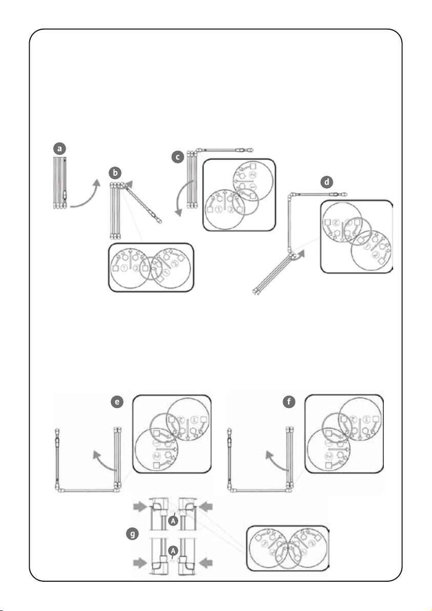
Hexagonal Configuration
To set up the playpen as a hexagon, unlock the hinge of the door panel (C)and rotate the panel
60° until the hexagon symbol (1) on the hinge lines up with the square symbol (2)on the
adjacent hinge as shown in (b). Secure the hinge in this position by pushing down on the hinge.
Unlock the adjacent hinge of the next panel and rotate the hinge with the door a further 60°
until the hexagons on both hinges align as shown in (c). Again, secure the hinge in this position
by pushing down on it.
To unfold the next panel, unlock the hinge at the other end
of the panel and rotate all of the remaining panels around
until the hexagon symbol (1) on the hinge lines up with the
square (1)on the hinge of the next element (d).
INSTALLATION - AS A PLAYPEN

Continue to unfold the remaining panels following the same routine (diagrams e to h).
To connect the last panel to the door panel first unlock and rotate the outer slat of the door
panel to the hexagon symbol (2). Then unlock and rotate the outer slat of the last panel to
the hexagon (1). Line up the connectors (A) to the corresponding openings on the door (C)
and gently push the two together until they click into place as shown (i). Lock both hinges
by pushing down on the panels, and finally check that all the other hinges are locked.
You can now place your base mat into the
playpen and secure it to each panel with the ties.

3. Rectangular Configuration
To set up the playpen as a rectangle, unlock the hinge of the door panel ‘C’ and rotate the panel
45° until the square symbol (1) on the hinge lines up with the square symbol (2) on the adjacent
hinge as shown in (b). Secure the hinge in this position by pushing down on the hinge.
Unlock the adjacent hinge of the next panel and rotate the hinge with the door a further 45°
until the square symbols on both hinges align as shown in (c). Again, secure the hinge in this
position by pushing down on it.
To unfold the next panel, unlock the hinge at the other end of the firstpanel and rotate all of
the remaining panels around until the straight line indicator (1) on the first panel lines up with
the square (1) on the hinge of the next panel (d). Secure the hinge in this position (push down ! ).
Unlock the next hinge and rotate the remaining panels around until the straight indicators line
up as shown (e). Continue to unfold the playpen as shown (diagrams f to h). To connect the last
panel to the door panel, first unlock and rotate the outer slat of the door panel to the square
symbol (2). Then unlock and rotate the outer slat of the last panel to the square (1).
Line up the connectors (A) to the corresponding openings on the door (C) and gently push the
two together until they click into place as shown (i). Lock both hinges by pushing down on the
panels, and finally check that all the other hinges are similarly locked.
4. Square Configuration
To set up the playpen as a square use only 3 panels and the door.
Unlock the hinge of the door panel (C) and rotate the panel 45° until the square symbol (1) on
the hinge lines up with the square symbol (2) on the adjacent hinge as shown in (b). Secure the
hinge in this position by pushing down on the hinge. Unlock the adjacent hinge of the next
panel and rotate the hinge with the door a further 45° until the square symbols on both hinges
align as shown in (c). Again, secure the hinge in this position by pushing down on it.
To unfold the next panel, unlock the hinge at the other end of the first panel and rotate all of
the remaining panels around until the square symbol (1) on the first panel lines up with the
square (1) on the hinge of the next panel (d). Secure the hinge in this position.
Unlock the next hinge and rotate the remaining panels around until the square indicators line
up as shown (e). Rotate the last panel until the square symbol (1) on the second panel lines up
with the square symbol (2) on the last panel. Finally release the hinge on the final panel and
rotate it until the square symbols line up.
To connect the last panel to the door panel first unlock and rotate the outer slat of the door
panel to the square symbol (2). Then unlock and rotate the outer slat of the last panel to the
square (1). Line up the connectors (A) to the corresponding openings on the door (C) and gently
push the two together until they click into place as shown (i). Lock both hinges by pushing
down on the panels, and finally check that all the other hinges are similarly locked.
Table of contents
Other Clippasafe Indoor Furnishing manuals


Popular Indoor Furnishing manuals by other brands

Regency
Regency LWMS3015 Assembly instructions

Furniture of America
Furniture of America CM7751C Assembly instructions

Safavieh Furniture
Safavieh Furniture Estella CNS5731 manual

PLACES OF STYLE
PLACES OF STYLE Ovalfuss Assembly instruction

Trasman
Trasman 1138 Bo1 Assembly manual

Costway
Costway JV10856 manual


