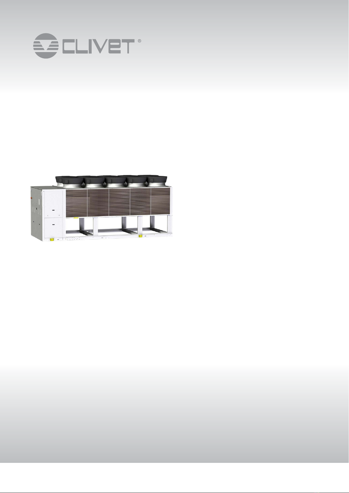
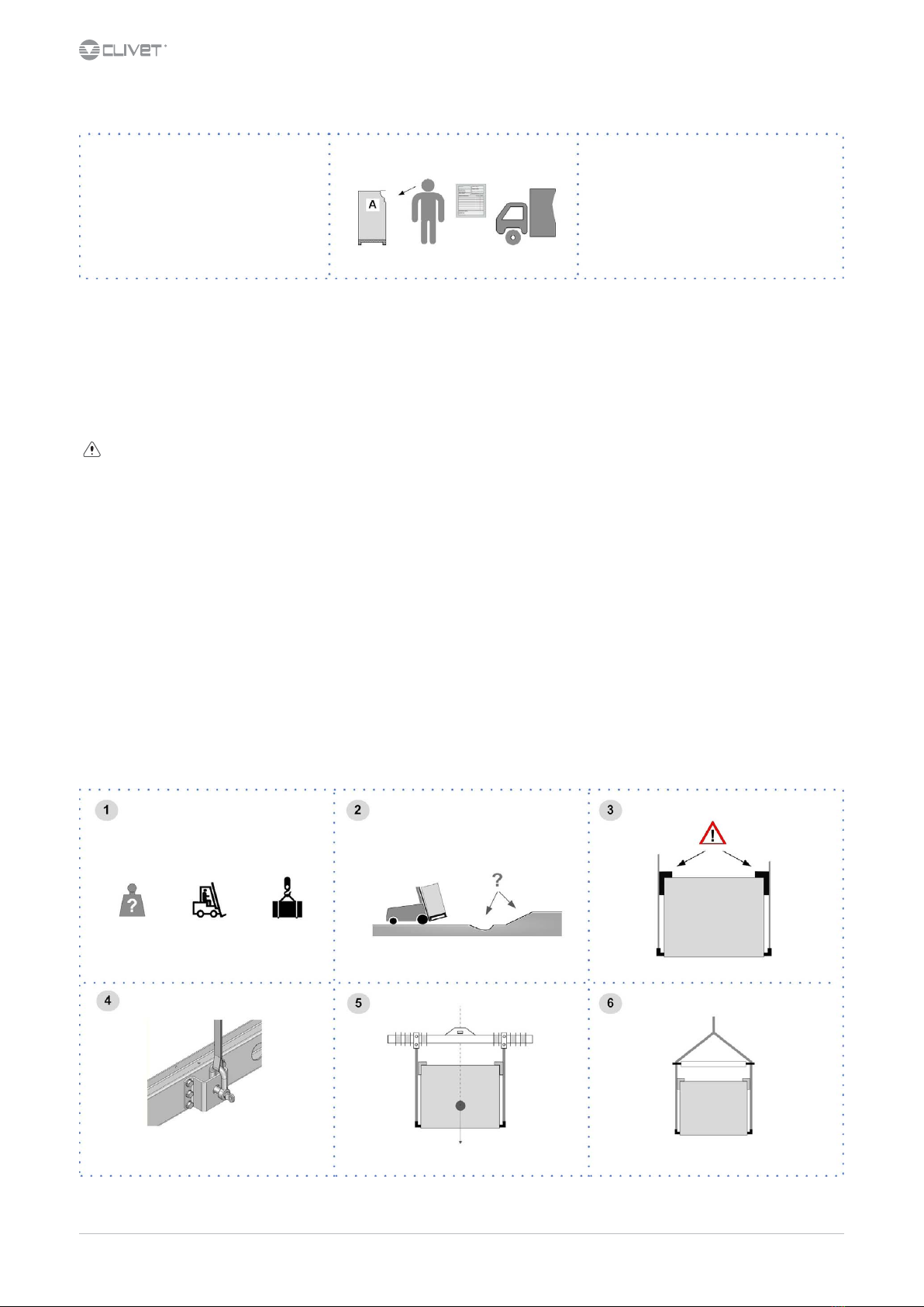
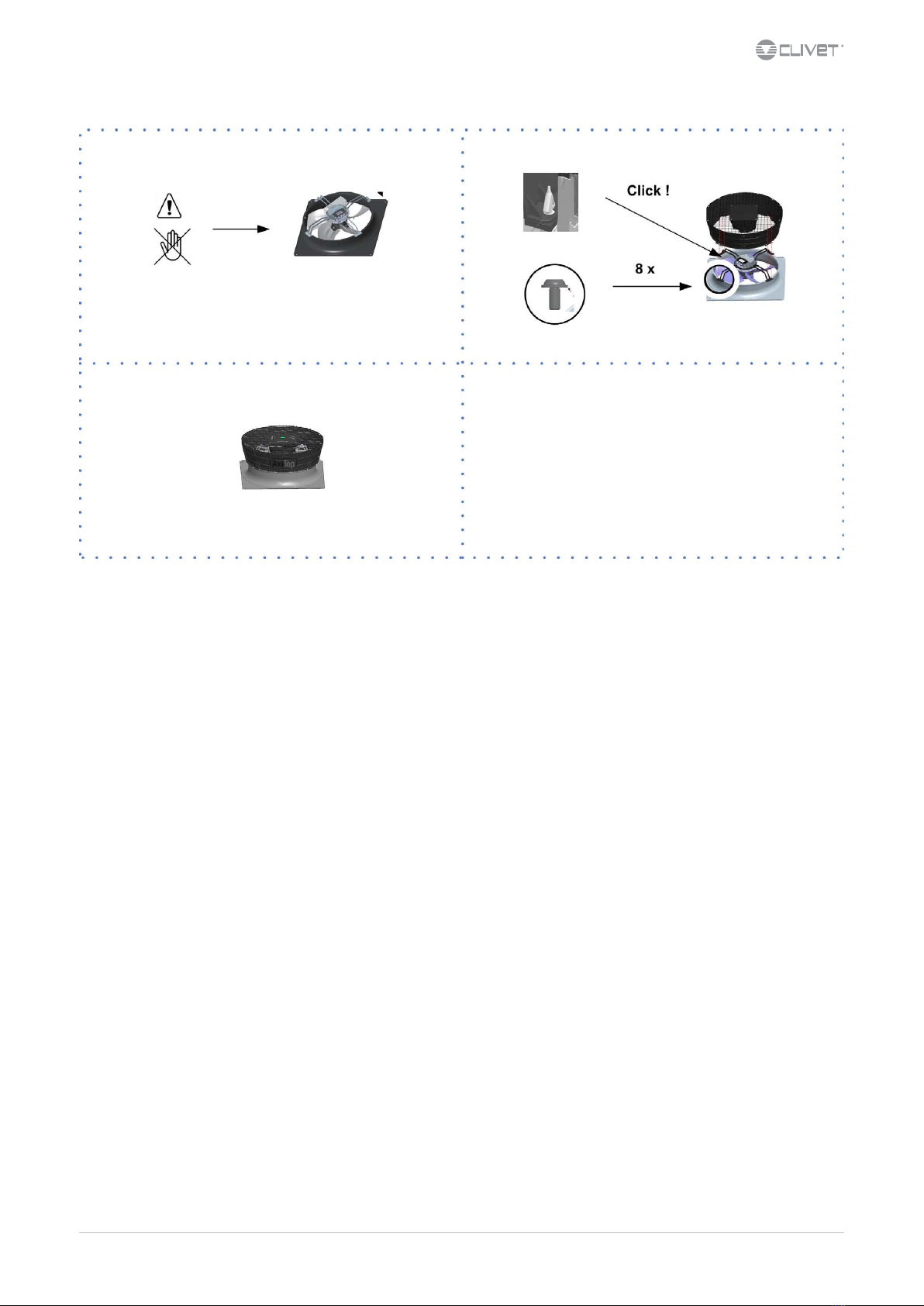
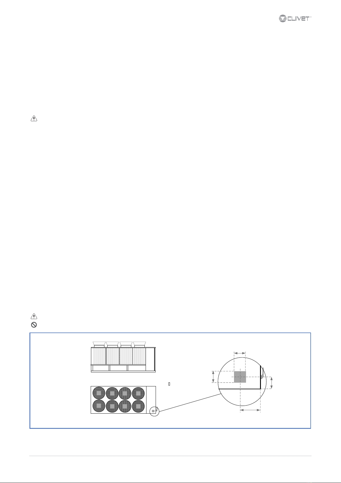
CLIVET WSAN-XSC3 MF Series User manual


This manual suits for next models
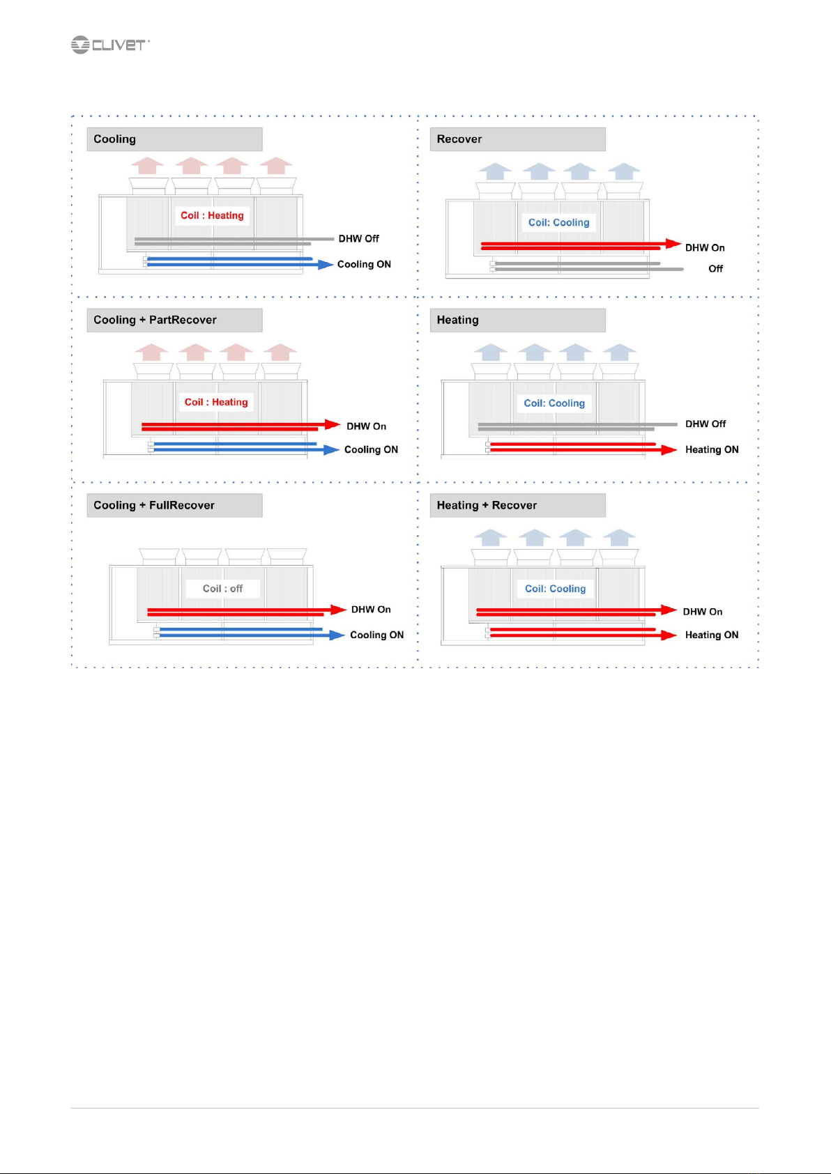
10
Other CLIVET Heat Pump manuals

CLIVET
CLIVET WSAN-YMi 21 R32 Reference manual

CLIVET
CLIVET WSAN-YSi R32 User manual

CLIVET
CLIVET WSAN-XSC 352 Guide

CLIVET
CLIVET MV6R-XMi Reference manual

CLIVET
CLIVET WSAN-XIN MF 18.2 User manual

CLIVET
CLIVET WSAN-XIN 21 User manual

CLIVET
CLIVET WSAN-EE 17 Guide

CLIVET
CLIVET WSAT-YSI User manual

CLIVET
CLIVET WSAN-XSC3 90.4 User manual

CLIVET
CLIVET CKN-XHE2i 10.1 User manual

CLIVET
CLIVET WSAN-XPR Series Guide

CLIVET
CLIVET WiSAN-YSE1 10.1 User manual

CLIVET
CLIVET Ceiling & Floor-SM2 IF2 53M Series Reference manual

CLIVET
CLIVET MSRN-XSC3 + CEV-XN User manual

CLIVET
CLIVET G3K0GB-1 User manual

CLIVET
CLIVET WSN-XIN Series User manual

CLIVET
CLIVET MSAT-XEE 8.2 User manual

CLIVET
CLIVET WSAN-XEE Series Guide

CLIVET
CLIVET WiSAN-YME 1 S 2.1 Reference manual

CLIVET
CLIVET WSAR-MT-E User manual


Popular Heat Pump manuals by other brands

Samsung
Samsung Max Heat DVM S2 Technical data book

Nibe
Nibe FIGHTER 1240 Installation and maintenance instructions

Ameristar
Ameristar M4MHW2209A installation instructions

Panasonic
Panasonic WH-SHF09D3E5 Service manual

Mitsubishi Electric
Mitsubishi Electric SUZ-SWM VA Series installation manual

Carrier
Carrier 50TFQ008-012 Installation, Start-Up and Service Instructions


