Cloos QINEO Micro 300 User manual

Operating Instructions /
Spare parts list
Micro 300
Portable Inverter
GT-D - 03.07.13 - Rev.0
PLEASE KEEP SAFELY FOR FUTURE REFERENCE

CARL CLOOS Schweisstechnik GmbH
Industriestrasse
35708 Haiger/Germany
Tel. +49 (0)2773/85-0
Fax. +49 (0)2773/85-275
mail: [email protected]
www.cloos.de
EU declaration of conformity No. CMM0516QNMI3_01
Product description: MIG/MAG welding machine
Model name: QINEO MICRO 300
Serial number: Refer to the nameplate on the back of the device
Manufacturer: CARL CLOOS Schweisstechnik GmbH
Address:
The manufacturer bears sole responsibility for issuing the declaration of conformity.
Low Voltage Directive:
EMC Directive:
RoHS Directive:
- EN 60974-1 Arc Welding Equipment
Part 1: Welding Power Sources
- EN 60974-5 Arc Welding Equipment
Part 5: Wire Feed Units
- EN 60974-10 Arc Welding Equipment
Part 10: Requirements of Electromagnetic Compatibility (EMC)
Signed for and in the name of:
CARL CLOOS Schweisstechnik GmbH
35708 Haiger, 30/05/16
Signature: Gerald Mies
Identification of signatory: Managing director
Agreement of the product stated with the regulations in the directives applied is verified with conformance to the
following standards and regulations:
Major conversions and add-ons which are not carried out by the manufacturer or the manufacturer’s authorised
representative(s) result in termination of this declaration of conformity.
Industriestrasse 22-36
35708 Haiger
Germany
2014/35/EU Directive of the European Parliament and of the Council of 26 February 2014 on the
harmonisation of laws of Member States relating to the making available on the market of electrical
equipment designed for use within certain voltage limits; Official Journal of the EU L96, 29/03/2014,
Pages 357 - 374
2014/30/EU Directive of the European Parliament and of the Council of 26 February 2014 on the
harmonisation of laws of Member States relating to electromagnetic compatibility; Official Journal of the
EU L96, 29/03/2014, Pages 79 - 106
2011/65 /EU Directive of the European Parliament and of the Council of 8 June 2011 on the restriction
of use of certain hazardous substances in electrical and electronic equipment; Official Journal of the EU
L174, 01/07/2011, Pages 88 - 110
The aforementioned products covered by the declaration satisfy the relevant
statutory provisions of the Union:

Micro 300
Cod.006.0001.1362
25/03/2013 v2.0
ENGLISH
3/32
1INTRODUCTION.........................................................................4
2FRONT PANEL...........................................................................4
3REAR PANEL.............................................................................5
4INSTALLATION..........................................................................5
4.1CONNECTIONSTOTHEELECTRICALMAINSNETWORK.
............................................................................................5
4.2PREPARINGFORMMAWELDING...................................5
4.3PREPARINGFORTIGWELDING.......................................6
4.4PREPARINGFORMIG/MAGWELDING.............................7
5USER INTERFACE.....................................................................9
6UNIT POWER-UP.....................................................................12
7RESET (LOAD FACTORY SETTINGS)...................................12
8SET-UP (INITIAL SET-UP OF THE WELDING POWER
SOURCE)...........................................................................................13
Remote Controller Selection............................................................13
Lock Status Activation......................................................................13
Push-Pull Activation.........................................................................13
Selection Of Burn Type....................................................................13
Quitting The Menu............................................................................13
8.1LOCKINGPROCEDURE..................................................14
8.1.1Enabling.......................................................................14
8.1.2Disabling......................................................................14
8.2GASFLOWADJUSTMENT..............................................15
9ALARMS MANAGEMENT........................................................15
AL. HEA...........................................................................................15
AL. Cur............................................................................................15
10WELDING SETTINGS..........................................................16
10.1ELECTRODEWELDING(MMA)......................................16
10.1.1MMA Parameters Setting (1st Level).......................16
10.1.2MMA Parameters Setting (2nd Level)......................16
10.2DCTIGWELDING............................................................16
10.2.1DC TIG MMA Parameters Setting (1st Level)..........16
10.2.2DC TIG Parameters Setting (GAS menu)................17
10.3MIG/MAGWELDING........................................................17
10.3.1Setting MIG/MAG parameters (Main Welding
Parameters)...............................................................................17
10.3.2MIG/MAG Parameters Setting (2nd Level)..............18
10.3.3MIG/MAG Parameters Setting (GAS menu)............18
11WELDING PARAMETERS LIST..........................................19
MMA welding current .......................................................................19
Hot-Start...........................................................................................19
Hot-Start...........................................................................................19
Burn-Back ........................................................................................19
Motor-Slope......................................................................................19
Soft-Start..........................................................................................19
Crater-Filler......................................................................................19
3 Levels Slope..................................................................................19
Arc-Force .........................................................................................19
Maximum TIG welding current.........................................................19
Post-gas time...................................................................................19
Post-gas time...................................................................................19
Pre-gas time.....................................................................................20
Remote controller selection .............................................................20
Lock status activation.......................................................................20
Push-pull activation..........................................................................20
Selection of burn type......................................................................20
12JOBS MANAGEMENT.........................................................21
12.1SAVINGAJOB.................................................................21
12.2LOADINGAUSERJOBOFFACTORYSETJOB............21
12.3DELETINGAJOB.............................................................21
13TORCH TRIGGER MODES..................................................22
13.12TLIFT-ARCWELDING...................................................22
13.24TLIFT-ARCWELDING...................................................22
13.32TMIG/MAGWELDING...................................................22
13.44TMIG/MAGWELDING...................................................22
13.53LEVELMIG/MAGWELDING.........................................22
14TECHNICAL DATA..............................................................23
15SPARE PARTS....................................................................24
15.1MICRO300......................................................................24
15.2WIREFEEDER ................................................................26
15.3WIREFEEDERROLLS....................................................27
16ELECTRICAL DIAGRAM.....................................................28
16.1MICRO300......................................................................28
16.2REMOTECONTROLLER ................................................30
16.2.1Rc03: Electrical Diagram.........................................30
16.2.2Rc04: Electrical Diagram.........................................30
16.2.3Rc05: Electrical Diagram.........................................31
16.2.4Rc06: Electrical Diagram.........................................31

Cod.006.0001.1362
25/03/2013 v2.0
ENGLISH Micro 300
4/32
1INTRODUCTION
IMPORTANT
This handbook must be consi
g
ned to the user prior to
installation and commissioning of the unit.
Read the "General prescriptions for use" handbook supplied
separatel
y
from this handbook before installin
g
and
commissioning the unit.
The meanin
g
of the s
y
mbols in this manual and the associated
precautionar
y
information are
g
iven in the "General prescriptions
for use”.
If the "General prescriptions for use" are not present, it is
mandator
y
to request a replacement cop
y
from the manufacturer
or from your dealer.
Retain these documents for future consultation.
KEY
This s
y
mbol identifies an action that occurs automaticall
y
as a
result of a previous action.
This s
y
mbol identifies additional information or a reference to
a different section of the manual containin
g
the associated
information.
§ This symbol identifies a reference to a chapter of the manual
This s
y
mbol accompanies important information concernin
g
the execution of the relevant operations
Micro 300 is a compact and rugged three-phase, synergic inverter
power source for MIG/MAG, MMA and TIG Lift welding.
Easy to transport, only 22kg , it is the best option for maintenance and
repair on fi eld, shipyard and off -shore operations.
Polarity change allows welding with self shielded wires.
Innovative unique HAC (Hybrid Arc Control) supplies a soft and very
stable MIG-MAG arc with excellent weld bead quality and minimal
spattering in any working conditions.
3T Mode allows both Hot Start and Crater Filler current setting, for
optimal penetration at start and crater fi lling at bead’s end.
Additional parameters, Motor Slope, Soft Start, Burn Back and Post
Gas are included for perfect arc ignition and optimum wire cutting at
the end of welding.
Microprocessor, inverter technology, digital displays, synergic curves
and memory locations for customized welding parameters assure
complete welding process repeatability. The inductance can be
adjusted electronically by means of the user interface in order to
optimize the arc.
A perfect wire feeding is guaranteed thanks to a 4-rolls motor drive
included in Micro 300.
The welding modes and procedures available are those indicated in
the table.
MODE PROCEDURE
MMA
2 STEP LIFT-ARC (2T)
TIG DC LIFT 4 STEP LIFT-ARC (4T)
2 STEP (2T)
4 STEP (4T)
MIG/MAG
3 LEVELS
Accessories that can be connected to the unit:
manual remote controller for remote adjustment of the welding
current.
2FRONT PANEL
1
2
3
4
5
1: Connector for remote control.
2: Positive pole welding socket.
3: Negative pole welding socket.
4: Polarity selector cable.
5: EURO TORCH welding socket.

Micro 300
Cod.006.0001.1362
25/03/2013 v2.0
ENGLISH
5/32
3REAR PANEL
1
2
3
4
5
1: Wire feed motor power transformer fuse.
TYPE Delayed acting (T)
AMPERAGE 630mA
VOLTAGE 500V
2: Welding power source ON/OFF switch.
3: Connector for gas pipe leading from cylinder.
4: Power cable
TOTAL LENGTH
(INCLUDING INTERNAL PART)3,5m
NUMBER AND CROSS SECTION OF
WIRES 4x2,5mm2
TYPE OF PLUG SUPPLIED Not supplied
5: Mains protection ON LED.
4INSTALLATION
4.1 CONNECTIONS TO THE ELECTRICAL MAINS
NETWORK
The characteristics of the mains power supply to which the equipment
shall be connected are given in the section entitled “technical data” on
page 23.
The machine can be connected to motorgenerators provided their
voltage is stabilised.
Connect/disconnect the various devices with the machine switched off.
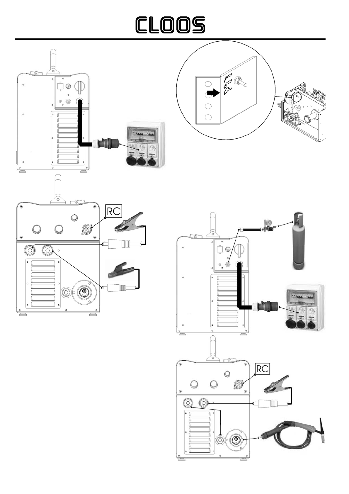
4.2 PREPARING FOR MMA WELDING
1.Turn the switch “OFF” (equipment switched off).
2.Connect the power cable to the power outlet.
3.Choose the electrode based on the type of material and thickness
of the workpiece to be welded.
4.Insert the electrode in the electrode holder.
5.Connect the plug of the electrode holder clamp to the welding socket
on the basis of the polarity required by the type of electrode in
question.
6.Connect the plug of the ground clamp to the welding socket on the
basis of the polarity required.
7.Connect the earth clamp to the workpiece being processed.
WARNING!
ELECTRIC SHOCK HAZARD!
Read the warnings highlighted by the following symbols in the
“General prescriptions for use”.
8.Set the welding power source ON/OFF switch to “I” (unit powered).
9.Use the selector in the spool housing to select MMA welding mode.
10. Set the required welding parameter values on the user interface.
11. The system is ready to start welding.
Cod.006.0001.1362
25/03/2013 v2.0
ENGLISH Micro 300
6/32
Preparing for MMA (polarity to basic electrode).
4.3 PREPARING FOR TIG WELDING
1.Set the welding power source ON/OFF switch to “O” (unit de-
energized).
2.Plug the power cable plug into a mains socketoutlet.
3.Connect the gas hose from the welding gas cylinder to the relative
socket.
4.Open the cylinder gas valve.
5.Choose the electrode on the basis of the type of material to be
welded and the thickness of the workpiece.
6.Insert the electrode in the TIG torch.
7.Connect the TIG torch plug to the EURO TORCH welding socket
8.Connect the plug of the polarity selector cable to the welding socket
on the basis of the polarity required.
9.Connect the plug of the ground clamp to the welding socket on the
basis of the polarity required.
10. Connect the earth clamp to the workpiece being processed.
11. Set the welding power source ON/OFF switch to “I” (unit powered).
12. Use the selector in the spool housing to select TIG welding mode.
13. Select the torch trigger procedure on the user interface.
14. Press the torch trigger with the torch well clear of any metal parts.
This serves to open the gas solenoid valve without striking the
welding arc.
15. Use the flow control valve to adjust the flow of gas as required
while the gas is flowing out.
16. Set the required welding parameter values on the user interface..
17. The system is ready to start welding.
Preparing for TIG (polarity for tungsten electrode)

Micro 300
Cod.006.0001.1362
25/03/2013 v2.0
ENGLISH
7/32
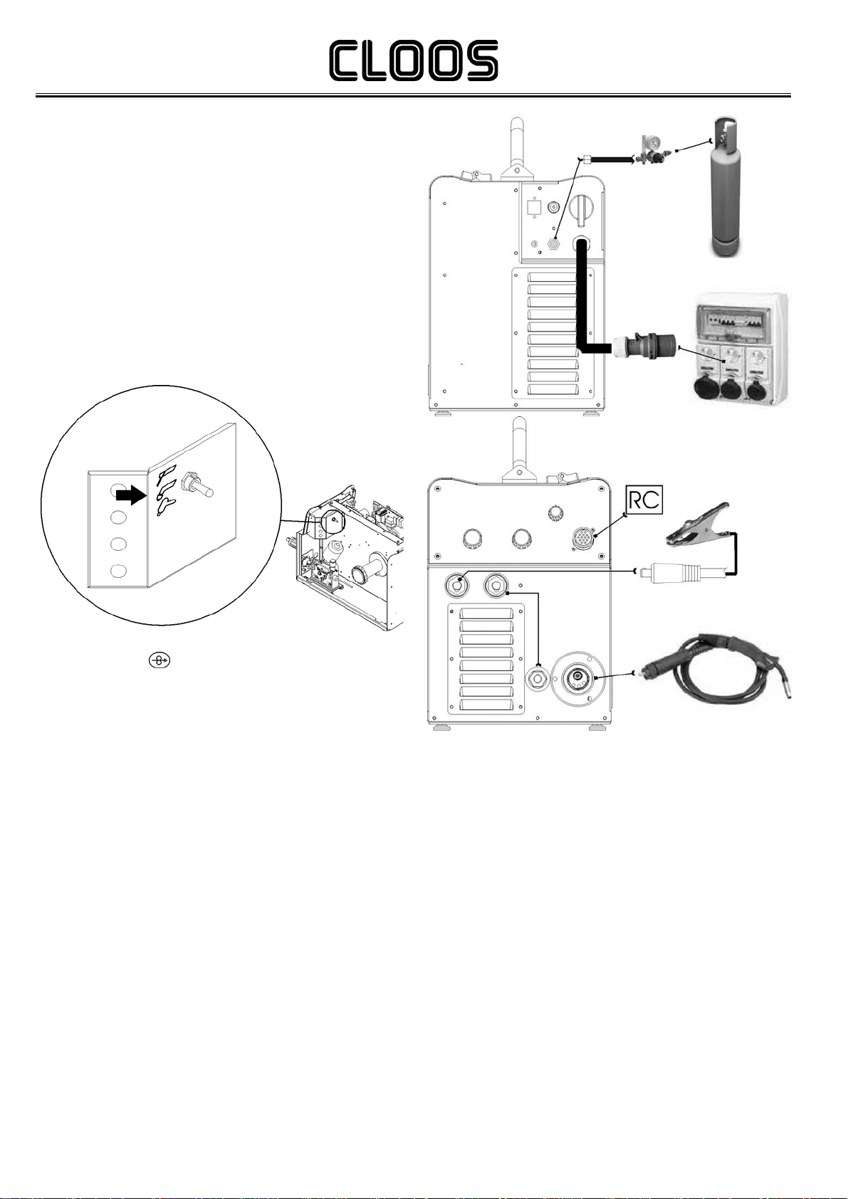
4.4 PREPARING FOR MIG/MAG WELDING
WIRE SPOOL POSITIONING
1.Open the unit side door to gain access to the spool compartment.
2.Unscrew the cap of the spool holder.
3.If necessary, fit an adapter for the wire spool.
4.Choose the wire on the basis of the workpiece thickness and
material type.
5.Fit the spool in the spool holder, ensuring it is located correctly.
6.Adjust the spool holder braking system by tightening/loosening the
screw in such a way that the wire feed force is not excessive and
when the spool stops rotating no excess wire is released.
7.Refit the plug.
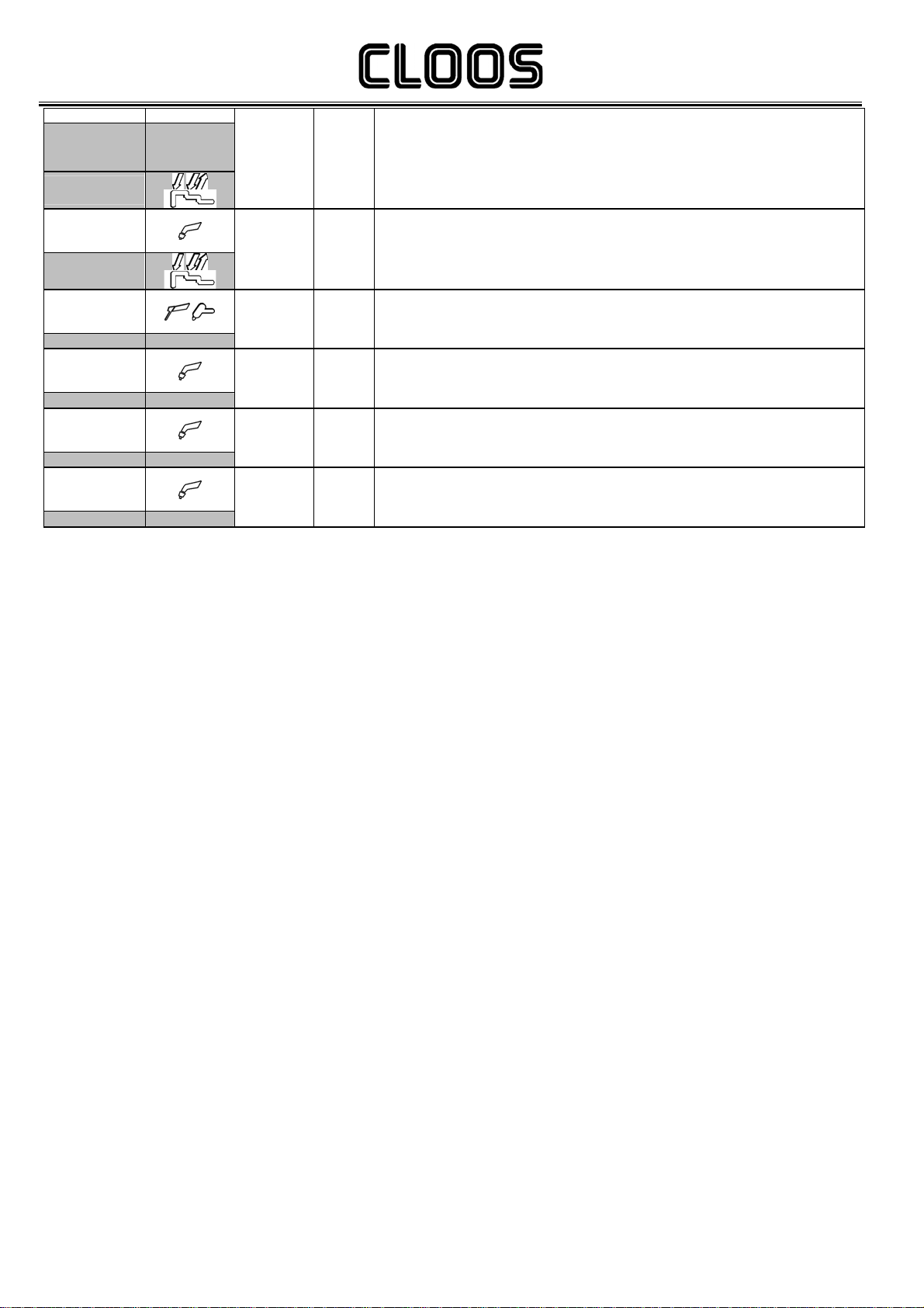
POSITIONING THE WIRE IN THE WIRE FEEDER
1.Lower the wire feeder pressure devices.
2.Raise the wire feeder pressure arms.
3.Remove the protective cover.
4.Check that the feed rolls are suitable for the wire gauge
§ 15.2
The diameter of the roll groove must be compatible with the
diameter of the welding wire
The roll must be of suitable shape in relation to the composition of
the wire material
The groove must feature a "U" profile for soft materials
(Aluminium and its alloys, CuSi3).
The groove must be "V" shaped for harder materials (SG2-SG3,
stainless steels)
Rolls with a knurled groove profile are available for flux-cored
wire.
5.Feed the wire between the wire feeder rolls and insert it into the
MIG/MAG TORCH connector plug.
Make sure the wire is located correctly in the roll grooves.
6.Close the wire feeder pressure arms.
7.Adjust the pressure system so that the arms press the wire with a
force that does not deform it while also ensuring constant feed
rate without slipping.
8.Refit the protective cover.
9.Close the spool compartment door in the side of the unit.
Cod.006.0001.1362
25/03/2013 v2.0
ENGLISH Micro 300
8/32
CONNECTIONS TO SOCKETS
1.Set the welding power source ON/OFF switch to “O” (unit de-
energized).
2.Plug the power cable plug into a mains socketoutlet.
3.Connect the gas hose from the welding gas cylinder to the relative
socket.
4.Open the cylinder gas valve.
5.Connect the MIG/MAG torch plug to the EURO TORCH welding
socket.
6.Connect the plug of the ground clamp to the welding socket on the
basis of the polarity required.
7.Connect the plug of the polarity selector cable to the welding socket
on the basis of the polarity required.
8.Connect the earth clamp to the workpiece being processed.
9.Set the welding power source ON/OFF switch to “I” (unit powered).
10. Use the selector in the spool housing to select MIG/MAG welding
mode.
11. Feed the wire through the torch until it protrudes from the tip,
pressing button on the unit front panel.
12. Select the torch trigger procedure on the user interface.
13. Press the torch trigger with the torch well clear of any metal parts.
This serves to open the gas solenoid valve without striking the
welding arc.
14. Use the flow control valve to adjust the flow of gas as required
while the gas is flowing out.
15. Set the required welding parameter values on the user interface..
16. On connecting and enabling a remote controller [RC] certain
settings can be modified from said controller without having to
take action on the user interface of the welding power source.
17. The system is ready to start welding.
Preparing for MIG/MAG
Micro 300
Cod.006.0001.1362
25/03/2013 v2.0
ENGLISH
9/32
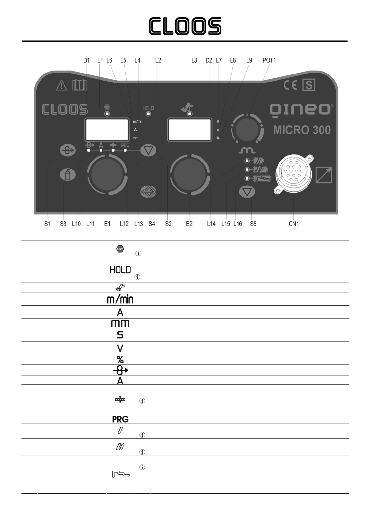
5USER INTERFACE
Code Name Symbol Description
This LED illuminates to show an anomaly in the operating conditions.
L1 ALARM § 9
When this LED illuminates the last voltage and current values measured during welding will be shown on displays D1-
D2.
L2 MEASURED VALUE The LED switches off when a new welding procedure is started, or when any of the welding settings is modified.
L3 SOCKETS POWERED This LED illuminates to confirm the presence of power on the output sockets.
L4 UNIT OF MEASUREMENT IN
METRES PER MINUTE
Illuminates to show that the value on display D1 is expressed in metres per minute.
L5 UNIT OF MEASUREMENT IN
AMPERES When this LED illuminates the Amperes value is shown on display D1.
L6 UNIT OF MEASUREMENT IN mm This LED indicates that the value shown on D1 is in mm
L7 UNIT OF MEASUREMENT IN
SECONDS This LED indicates that the value shown on D2 is in seconds or milliseconds
L8 UNIT OF MEASUREMENT IN
VOLTS When this LED illuminates a Voltage value is shown on display D2.
L9 UNIT OF MEASUREMENT IN % This LED indicates that the value shown on D2 is in a percentage
L10 WIRE FEED RATE Illuminates to show that the wire feed rate value can be set on display D1
L11 AMPERES Illuminates to show that the welding current value in Amperes can be set on display D1
Illuminates to confirm the possibility of setting the recommended base material thickness is displayed on D1.
L12 THICKNESS Reference is made to "T" fillet welds on identical thicknesses.
The relative value is purely guideline.
L13 PROGRAMS Illuminates to show that the required Synergic welding program can be set
This LED illuminates to show that the torch trigger 2 times procedure is selected.
L14 TWO TIMES PROCEDURE §. 13.1
This LED illuminates to show that the torch trigger 4 times procedure is selected.
L15 FOUR TIMES PROCEDURE §. 13.2
This LED illuminates to show that the torch trigger 3 Level procedure is selected.
L16 THREE LEVEL PROCEDURE The procedure can be activated in synergic programs in MIG/MAG mode.
§. 13.5

Cod.006.0001.1362
25/03/2013 v2.0
ENGLISH Micro 300
10/32
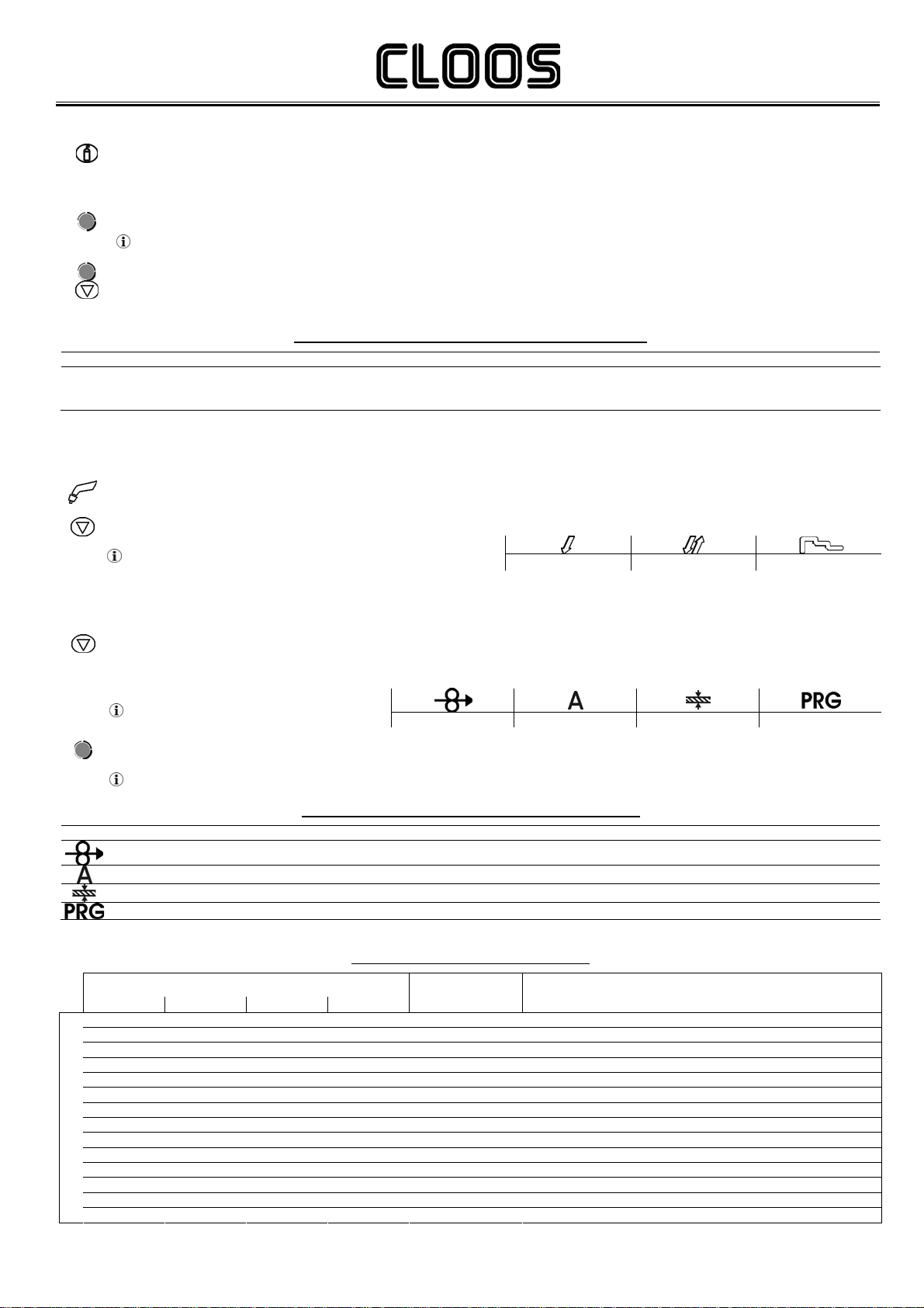
Code Name Symbol Description
Parameters/functions setting
Manual MIG/MAG mode
The display shows the programmed wire feed rate.
Synergic MIG/MAG mode
The display shows the value of the selected main welding parameter.
The main welding parameters can be selected with button S2
Programs setting
The display shows the message P “program no.”
Welding
The display shows the effective amperes value during welding
The display shows the variation of the main welding parameter.
The main welding parameter is selected with button S2 and can be set using encoder E1
Menu function
The display shows the acronym of the parameter or function to be adjusted
D1 AMPERES DISPLAY
HOLD function
The display shows the latest measured current value
Parameters/functions setting
Manual and Synergic MIG/MAG mode
The display shows the programmed voltage
Programs setting
The display shows the acronym of the material to be welded on the basis of the selected synergic curve
Welding
The display shows the effective voltage value during welding
The display shows the arc correction value imposed by the operator with respect to the default value of the synergic
curve.
Arc correction is performed by means of encoder E2.
0.0 V is the default value for horizontal or frontal welding.
A value >0 produces an increase in the length of the welding arc.
A value <0 produces a shorter arc. Menu function
The display shows the value of the parameter or function to be adjusted.
D2 VOLTAGE DISPLAY
HOLD function
The display shows the latest measured voltage value.
MIG/MAG mode
This button activates wire feed to insert it through the MIG/MAG torch.
The insertion speed is 1.2m/min for 3 seconds, subsequently increasing to 10m/min.
When the button is released wire feed is interrupted.
This function produces a slower feed rate and hence greater precision when inserting the wire when it enters the
torch nozzle.
S1 INSERTION BUTTON
MMA mode
This button is not enabled.
DC TIG mode
This button is not enabled.
This button opens the gas solenoid valve to fill the circuit and calibrate the pressure with the regulator on the gas
cylinder.
§.8.2
S3 GAS
BUTTON GAS menu function
Hold down the button for 3 seconds to open the Menu
MMA mode
This button is not enabled.
MIG/MAG mode
This button selects the torch trigger mode
§.13
TIG mode
This button selects the torch trigger mode
S5 TORCH TRIGGER MODE
SELECTION
§.13

Micro 300
Cod.006.0001.1362
25/03/2013 v2.0
ENGLISH
11/32
Code Name Symbol Description
Parameters/functions setting
Manual MIG/MAG mode:
The button selects the parameters highlighted by illumination of the following LEDs:
Synergic MIG/MAG mode:
The button selects the parameters highlighted by illumination of the following LEDs:
In all welding modes
This button provides the facility to gain access to the secondary parameters adjustment menu
Powering up the unit
This button opens the initial setup menu
S2 PROGRAMS BUTTON
§ 8
S4 JOB
BUTTON Press the button once to open the JOB upload menu
Hold down the button for 3 seconds to gain access to the JOB save/delete Menu
Parameters/functions setting
Manual MIG/MAG mode
The encoder sets the wire feed rate.
Synergic MIG/MAG mode
The encoder sets the main adjustment value.
By changing the main adjustment value shown on display D1, the voltage value of the synergic curve shown on
display D2 changes accordingly. Programs setting
The encoder selects the synergic program to be uploaded.
Menu function
The encoder selects the function or parameter to be adjusted.
E1 WIRE FEED RATE/SYNERGY
PROGRAMMING
Welding
The encoder selects the main welding parameter to be set.
Manual MIG/MAG mode
The encoder sets the welding voltage.
Synergic MIG/MAG mode
The encoder sets the arc correction.
Programs setting
The encoder selects the MIG/MAG welding program.
E2 VOLTAGE SETTING
Menu function
The encoder sets the value of the selected function or parameter.
POT1 INDUCTANCE POTENTIOMETER
Manual MIG/MAG mode
The potentiometer sets the inductance value
Synergic MIG/MAG mode
The potentiometer sets the inductance value from the minimum to the maximum permissible value in accordance with
the selected synergic curve
SEL1 PROCEDURES SELECTOR Selects the welding mode

Cod.006.0001.1362
25/03/2013 v2.0
ENGLISH Micro 300
12/32
6UNIT POWER-UP
Set the welding power source ON/OFF switch to “I” to switch on the unit.
F x.x The message appears on displays D2 for a few seconds
F x.x= software version
A L. H E A. The message appears on displays D1-D2.
First power-up or power-ups following a RESET procedure
The welding power source sets up for welding with the factory presets
Subsequent power-ups
The welding power source sets up for welding in the latest stable welding configuration that was active at the time of
power-off
7RESET (LOAD FACTORY SETTINGS)
The reset procedure involves complete restoration of the default values, parameters and memory settings set in the factory.
All memory locations will be reset and hence all your personal welding settings will be lost!
The reset procedure is useful in the following cases:
Too many changes made to the welding parameters so user finds it difficult to restore defaults.
Unidentified software problems that prevent the welding power source from functioning correctly.
Set the welding power source ON/OFF switch to “O” to switch the unit off.
S3 S5
Hold down both buttons simultaneously
Set the weldin
g
power source ON/OFF switch to “I” to switch
on the unit.
SIMULTANEOUS ACTIONS
S3 S5
Release buttons
r E C F A C The message appears on displays D1-D2.
Wait for the memory clear procedure to terminate
Tab. 1 Factory settings in MIG/MAG mode
PARAMETER VALUE UNIT OF MEASUREMENT
Wire feed rate (D1) 5.0 m/min
Voltage (D2) 20 V
Arc Correction 0.0 V
Soft-Start 30 %
Motor-Slope 40 ms
Bourn-Back 26 ms
Hot-Start 130 %
Crater-Filler 80 %
3 Levels Slope 0.5 s
Post-gas time 0.3 s
Pre-gas time 0 s
Trigger 2 Step Not Present
Remote controller selection OFF Not Present
Lock status activation OFF Not Present
Push-pull activation OFF Not Present
Selection of burn type Std Not Present
Sequences and Jobs All deleted Not Present

Micro 300
Cod.006.0001.1362
25/03/2013 v2.0
ENGLISH
13/32
8SET-UP (INITIAL SET-UP OF THE WELDING POWER SOURCE)
Set the welding power source ON/OFF switch to “O” to switch the unit off.
SEL1
Set the selector to the symbol to select MIG/MAG welding mode
S2 Hold down the button
Set the welding power source ON/OFF switch to “I” to switch on the unit.
SIMULTANEOUS ACTIONS
Set uP The message appears on displays D1-D2 for a few seconds
rC. The acronym relative to the setting to be edited is shown on display D1
oFF The value relative to the selected setting appears on display D2
E1 Use the encoder to scroll the list of settings to edit
Tab. 2 Setup settings
E2 Using the encoder, edit the value of the selected setting
E1 Select “ESC” with the encoder
S2
Press any button to save the setting and quit the Menu
Tab. 2 Setup settings
SETTING Acronym on D1 Value on D2 NOTES
oFF No remote controller enabled
Setting from user interface
3
Enables operation of connected remote controller RC03 (1 potentiometer)
Wiring diagram 16.2.1 page 30
JOBs can be retrieved
When a JOB is active the RC is inhibited
The JOB can only be quit from the interface panel
4
Enables operation of connected remote controller RC04 (2 potentiometers)
Wiring diagram 16.2.2 page 30
JOBs can be retrieved
When a JOB is active the RC is inhibited
The JOB can only be quit from the interface panel
5
Enables operation of connected remote controller RC05 (1 UP/DOWN)
Wiring diagram 16.2.3 page 31
JOBs can be retrieved
The JOB can be quit both from the panel and from RC
Remote Controller Selection rC
6
Enables operation of connected remote controller RC06 (2 UP/DOWN)
Wiring diagram 16.2.4 page 31
JOBs can be retrieved
The JOB can be quit both from the panel and from RC
oFF All adjustments are disabled.
1 All adjustments are disabled with the exceptions shown in Tab. 3page 14.
2 All adjustments are disabled with the exceptions shown in Tab. 3page 14.
Lock Status Activation LoC
3 The Loc 3 setting becomes active only when a JOB is loaded
All adjustments are disabled with the exceptions shown in Tab. 3 page 14.
When no JOB is loaded, the user interface is completely unlocked
oFF The setting activates the push-pull torch
Push-Pull Activation PP on The setting deactivates the push-pull torch
SPc The setting activates Special burning
Selection Of Burn Type bb. Std The setting activates Standard burning
Quitting The Menu ESC To quit the menu select this setting and press button S1

Cod.006.0001.1362
25/03/2013 v2.0
ENGLISH Micro 300
14/32
8.1 LOCKING PROCEDURE
The locks are enabled only in MIG/MAG welding mode.
The procedure inhibits unit adjustments, allowing the user to modify only certain settings depending on the selected lock status.
The procedure is used to prevent accidental alteration of the unit settings and welding settings by the operator.
8.1.1 ENABLING
If no locking status is selected (LoC = oFF) and if you wish to set up a limitation on use of the power source, display the Loc function in the
SETUP menu.
Open the Setup menu
§ 8
rC. The acronym relative to the setting to be edited is shown on display D1
oFF The value relative to the selected setting appears on display D2
E1 Select “LoC” with the encoder
E2 Use the encoder to select the required lock status
Depending on the selected Lock, certain functions will remain enabled
Tab. 3 Functions not disabled by Locks
E1 Select “ESC” with the encoder
S2
Press any button to save the setting and quit the Menu
Tab. 3 Functions not disabled by Locks
LoC User interface RC03 RC04 RC05 RC06
1
Selection of torch trigger procedure (button S5)
Display of main welding parameters (button S2)
Arc correction (encoder E2)
Wire insertion (button S1)
Gas test (button S3)
Arc correction
(Potentiometer Pot2) Arc correction (UP/DOWN
lever 2)
2
Selection of torch trigger procedure (button S5)
Display of main welding parameters (button S2)
Arc correction (encoder E2)
Synergy (encoder E1)
Wire insertion (button S1)
Gas test (button S3)
All adjustments enabled
All adjustments enabled All adjustments enabled All adjustments enabled
3
Selection of torch trigger procedure (button S5)
Display of main welding parameters (button S2)
JOB selection (encoder E2)
Wire insertion (button S1)
Gas test (button S3)
Scroll JOBS (UP/DOWN
lever 1) Scroll JOBS (UP/DOWN
lever 1)
8.1.2 DISABLING
If a lock status is selected, you can only edit parameters permitted by the currently active lock status.
Open the Setup menu
§ 8
rC. The acronym relative to the setting to be edited is shown on display D1
oFF The value relative to the selected setting appears on display D2
E1 Select “LoC” with the encoder
E2 Select “oFF” with the encoder
E1 Select “ESC” with the encoder
S2
Press any button to save the setting and quit the Menu

Micro 300
Cod.006.0001.1362
25/03/2013 v2.0
ENGLISH
15/32
8.2 GAS FLOW ADJUSTMENT
When the unit is powered on the solenoid valve opens for 1 second.
This serves to fill the gas circuit.
S3
Open the gas solenoid valve by pressing and releasing the button
Adjust the pressure of gas flowing from the torch by means of the flow meter connected to the gas cylinder
S3
Close the gas solenoid valve by pressing and releasing the button
The solenoid valve closes automatically after 30 seconds
9ALARMS MANAGEMENT
The LED illuminates in the presence of alarms
A L. H E A. An alarm message appears on displays D1-D2
Tab. 4 Alarm messages
MESSAGE MEANING EVENT CHECKS
AL. HEA.
Overheating Alarm
Indicates tripping of the welding power
source thermal protection.
Leave the unit running so that the
overheated components cool as rapidly as
possible.
When the unit has cooled, the welding
power source will reset automatically.
All functions disabled.
Exceptions:
cooling fan
cooler (if switched on)
Make sure that the power required by the
welding process is lower than the maximum
rated power output.
Check that the operating conditions are in
compliance with the welding power source
data plate specifications.
Check for the presence of adequate air
circulation around the welding power source.
AL. Cur.
Current Surge Alarm
Indicates tripping of the welding power
source current surge protection.
Exit the alarm state by performing one of
the following actions:
- Press any button on the user interface
- Switch off the power source
An audible signal will sound (buzzer)
Muting the audible signal:
- in torch trigger procedure T2, release the torch trigger.
- in torch trigger procedure 4T or 4TS the alarm mutes automatically
after 5 seconds.
All functions disabled.
Exceptions:
- cooling fan
- cooler (if switched on)
Check that the programmed arc voltage value
is not too high in relation to the thickness of
the work to be welded.

Cod.006.0001.1362
25/03/2013 v2.0
ENGLISH Micro 300
16/32
10 WELDING SETTINGS
10.1 ELECTRODE WELDING (MMA)
SEL1
Set the selector to the symbol to select MMA welding mode
MMA The message appears on displays D2
10.1.1 MMAPARAMETERS SETTING (1ST LEVEL)
E1 Using the encoder, edit the value of the selected setting
Tab. 5 Parameters of the 1st level Menu in MMA mode
80 The value relative to the selected setting appears on display D1
Tab. 5 Parameters of the 1st level Menu in MMA mode
PARAMETER MIN DEFAULT MAX NOTES
- MMA WELDING CURRENT 10A 80A 250A
10.1.2 MMAPARAMETERS SETTING (2ND LEVEL)
S2
Hold down the button for 3 seconds to gain access to the 2nd level Menu
H.-S. The acronym relative to the setting to be edited is shown on display D1
50 The value relative to the selected setting appears on display D2
E1 Use the encoder to scroll the list of settings to edit
Tab. 6 Parameters of the 2nd level Menu in MMA mode
E2 Using the encoder, edit the value of the selected setting
Press any button to save the setting and quit the Menu
Tab. 6 Parameters of the 2nd level Menu in MMA mode
PARAMETER MIN DEFAULT MAX NOTES
H.S. HOT-START 0% 50% 100%
A.F. ARC-FORCE 0% 30% 100%
10.2 DC TIG WELDING
SEL1
Set the selector to the symbol to select TIG welding mode
tIG The message appears on displays D2
S5
Press the button to select the torch trigger procedure
The following torch trigger procedures are available: (2 STEPS) (4 STEPS)
10.2.1 DCTIG MMAPARAMETERS SETTING (1ST LEVEL)
E1 Using the encoder, edit the value of the selected setting
Tab. 7 1st level Menu parameters in continuous TIG mode
80 The value relative to the selected setting appears on display D1
Tab. 7 1st level Menu parameters in continuous TIG mode
PARAMETER MIN DEFAULT MAX NOTES
- TIG WELDING CURRENT 10A 80A 250A
Micro 300
Cod.006.0001.1362
25/03/2013 v2.0
ENGLISH
17/32
10.2.2 DCTIG PARAMETERS SETTING (GASMENU)
S3
Hold down the button for 3 seconds to gain access to the 2nd level Menu
Po.G. The acronym relative to the setting to be edited is shown on display D1
3 The value relative to the selected setting appears on display D2
E1 Use the encoder to scroll the list of settings to edit
Tab. 8 GAS Menu parameters in continuous TIG mode
E2 Using the encoder, edit the value of the selected setting
Press any button to save the setting and quit the Menu
Tab. 8 GAS Menu parameters in continuous TIG mode
PARAMETER MIN DEFAULT MAX NOTES
Po.G. POST-GAS TIME 0s 3s 10.0s When a synergic program is loaded the default value of the parameter is
defined automatically by the software and the message “SYN” will be shown on
the display
10.3 MIG/MAG WELDING
SEL1
Set the selector to the symbol to select MIG/MAG welding mode MIG/MAG
S5
Press the button to select the torch trigger procedure
The following torch trigger procedures are available: (2 STEPS) (4 STEPS) (3 LIVELLI)
10.3.1 SETTING MIG/MAGPARAMETERS (MAIN WELDING PARAMETERS)
S2
Press the button to scroll the list of settings to edit
The LED associated with the selected setting will illuminate
The value relative to the selected setting appears on display D1
The following settings are available WIRE FEED RATE AMPERES THICKNESS PROGRAMS
E1 Using the encoder, edit the value of the selected setting
Tab. 9 Main welding parameters in MIG/MAG mode
The value is saved automatically
Tab. 9 Main welding parameters in MIG/MAG mode
PARAMETER MIN DEFAULT MAX NOTES
WIRE FEED RATE 1m/min 20m/min
MIG/MAG WELDING CURRENT Syn Not enabled with manual program P0
THICKNESS Syn Not enabled with manual program P0
PROGRAMS P0 P0 P34 Tab. 10 Programmed synergic curves
Tab. 10 Programmed synergic curves
WIRE DIAMETER
0.8 1.0 1.2 1.4 ACRONYM WIRE MATERIAL (GAS MIXTURE)
P0 P0 P0 P0 MAn MANUAL
P1 P2 P3 -- FE SG2/SG3 (80%Ar-20%CO2)
P4 P5 P6 -- FE SG2/SG3 (92%Ar- 8%CO2)
P7 P8 P9 -- FE SG2/SG3 (100%CO2)
P10 P11 P12 -- S.S. INOX 308 (98%Ar-2%CO2)
P13 P14 P15 -- S.S. INOX 316 (98%Ar-2%CO2)
P16 P17 P18 -- AL AlMg5 (100%Ar)
P19 P20 P21 -- AL AlSi5 (100%Ar)
P22 P23 P24 -- CU.S. CuSi3 (100%Ar)
P25 P26 P27 CU.A. CuAl8(100%Ar)
-- -- P28 P29 rFC RFCW (80%Ar-20%CO2)
-- -- P30 P31 bFC BFCW (80%Ar-20%CO2)
-- -- P32 P33 MFC MFCW (80%Ar-20%CO2)
P
R
O
G
R
A
M
P34 -- -- -- nPr FREE PROGRAMS
Cod.006.0001.1362
25/03/2013 v2.0
ENGLISH Micro 300
18/32
10.3.2 MIG/MAGPARAMETERS SETTING (2ND LEVEL)
S2
Hold down the button for 3 seconds to gain access to the 2nd level Menu
S.-S. The acronym relative to the setting to be edited is shown on display D1
30 The value relative to the selected setting appears on display D2
E1 Use the encoder to scroll the list of settings to edit
Tab. 11 2nd level Menu parameters in MIG/MAG mode
E2 Using the encoder, edit the value of the selected setting
Press any button to save the setting and quit the Menu
Tab. 11 2nd level Menu parameters in MIG/MAG mode
PARAMETER MIN DEFAULT MAX NOTES
H.-S. HOT-START 1% 130% 200% Available with 3 Levels procedure selected
C.-F. CRATER-FILLER 1% 80% 200% Available with 3 Levels procedure selected
S.3L. 3 LEVELS SLOPE 0.1s 0.5s 10.0s Available with 3 Levels procedure selected
S.-S. SOFT-START 10% 30% 100%
When a synergic program is loaded the default value of the parameter is
defined automatically by the software and the message “SYN” will be shown on
the display
SLO. MOTOR SLOPE 0ms 40ms 200ms When a synergic program is loaded the default value of the parameter is
defined automatically by the software and the message “SYN” will be shown on
the display
b.-b. BOURN BACK 0ms 26ms 100ms When a synergic program is loaded the default value of the parameter is
defined automatically by the software and the message “SYN” will be shown on
the display
10.3.3 MIG/MAGPARAMETERS SETTING (GASMENU)
S3
Hold down the button for 3 seconds to gain access to the 2nd level Menu
Po.G. The acronym relative to the setting to be edited is shown on display D1
0.3 The value relative to the selected setting appears on display D2
E1 Use the encoder to scroll the list of settings to edit
Tab. 12 GAS Menu parameters in MIG/MAG mode
E2 Using the encoder, edit the value of the selected setting
Press any button to save the setting and quit the Menu
Tab. 12 GAS Menu parameters in MIG/MAG mode
PARAMETER MIN DEFAULT MAX NOTES
Po.G. POST-GAS TIME 0s 0.3s 10.0s When a synergic program is loaded the default value of the parameter is
defined automatically by the software and the message “SYN” will be shown on
the display
P.G. PRE-GAS TIME 0s 0s 10.0s When a synergic program is loaded the default value of the parameter is
defined automatically by the software and the message “SYN” will be shown on
the display

Micro 300
Cod.006.0001.1362
25/03/2013 v2.0
ENGLISH
19/32
11 WELDING PARAMETERS LIST
Tab. 13 Welding parameters/welding functions enabling
PARAMETER MODE
MIN/DEFAULT/MAX
(UNIT OF
MEASUREMENT) PROCEDURE SETTING ACRONYM
NOTES
MMA welding current
10/80/250
(A) 1st level Menu
(§ 10.1.1) - Output current value during MMA welding
Hot-Start
0/50/100
(%) 2nd level Menu
(§ 10.1.2) H.S.
This parameter aids electrode melting at the time of arc striking.
Consequences of a higher value:
Easier arc strike
Increased spatter at welding start
Increase of strike area
Consequences of a lower value:
More difficult arc strike
Less spatter at welding start
Smaller strike area
Hot-Start
1/130/200
(%)
2nd level Menu
(§ 10.3.2) H.S.
This function is useful when using aluminium alloy welding wire
Consequences of a higher value:
Greater heat output
Greater penetration
Consequences of a lower value:
"Cold" weld bead
Burn-Back
0/26/100
(ms)
2nd level Menu
(§ 10.3.2) b-b
Establishes the wire cutting length at the end of the welding process
Consequences of a higher value:
-Shortening of the length of wire that protrudes from the torch
Consequences of a lower value:
-Increase of the length of wire that protrudes from the torch
Motor-Slope
0/40/200
(ms)
2nd level Menu
(§ 10.3.2) SLO Time required to switch from soft-start speed to welding speed
Soft-Start
10/30/100
(%)
2nd level Menu
(§ 10.3.2) S.S. Determines the wire feed rate before the arc strike
Calculated as a percentage of the programmed wire feed rate
Crater-Filler
1/80/200
(%)
2nd level Menu
(§ 10.3.2)
C-F
This parameter serves to obtain a uniform deposit at the end of the welding process to fill the crater with a
reduced wire feed rate to facilitate the deposition of filler material.
By keeping the torch trigger pressed during the 3rd time, the wire feed rate is reduced (crater filler speed)
thereby ensuring optimal crater filling, until the postgas time is started by releasing the torch trigger (4th
time).
Consequences of a higher value:
-Difficult crater filling (values greater than 100%)
Consequences of a lower value:
-Cold welding (values close to 1%)
3 Levels Slope
0.1/0.5/10
(s)
2nd level Menu
(§ 10.3.2) S.3L Establishes the duration of the slope between the 1stand 2nd time and between the 3rd and 4th time.
Arc-Force
0/30/100
(%) 2nd level Menu
(§ 10.1.2) A.F.
This parameter helps to avoid electrode sticking during welding
Consequences of a higher value:
Fluidity during welding
Welding arc stability
Greater electrode fusion in workpiece
More welding spatter
Consequences of a lower value:
The arc is extinguished more easily
Less welding spatter
Maximum TIG
welding current
5/80/320
(A)
1st level Menu
(§ 10.2.1) - Current output value during TIG welding
Post-gas time
0/3/10
(s)
GAS menu
(§ 10.2.2)
Post-gas time GAS menu
(§ 10.3.3)
Po.G. Time of post gas delivery when the welding arc is extinguished.
Consequences of a higher value:
More effective pickling (improved appearance of workpiece at the end of the welding pass).
Higher gas consumption.
Consequences of a lower value:
Lower gas consumption.
Oxidation of electrode tip (more difficult arc strike).
Cod.006.0001.1362
25/03/2013 v2.0
ENGLISH Micro 300
20/32
PARAMETER MODE
MIN/DEFAULT/MAX
(UNIT OF
MEASUREMENT) PROCEDURE SETTING ACRONYM NOTES
0/3/10
(s)
Pre-gas time
0/0.1/10.0
(s)
GAS menu
(§ 10.3.3) P.G Time of gas delivery before the arc strike.
Consequences of a higher value:
This parameter allows a shielded environment to be created, thereby eliminating contaminants at the
start of the welding pass.
Remote controller
selection
SETUP menu
(§8) rC
Lock status activation
SETUP menu
(§8) LoC
Push-pull activation
SETUP menu
(§8) PP
Selection of burn type
SETUP menu
(§8) bb.
Table of contents
Other Cloos Inverter manuals


Popular Inverter manuals by other brands


Omron
Omron JZA user manual

Olimpia splendid
Olimpia splendid Unico Instructions for installation, use and maintenance

Wagan
Wagan 9751 user manual

Mitsubishi Electric
Mitsubishi Electric FR-A720-00030-NA instruction manual

Siemens
Siemens MICROMASTER 420 operating instructions

iTechworld
iTechworld 1000W user guide