Telos Alliance Linear Acoustic SDI XNODE User manual
LINEAR ACOUSTIC®
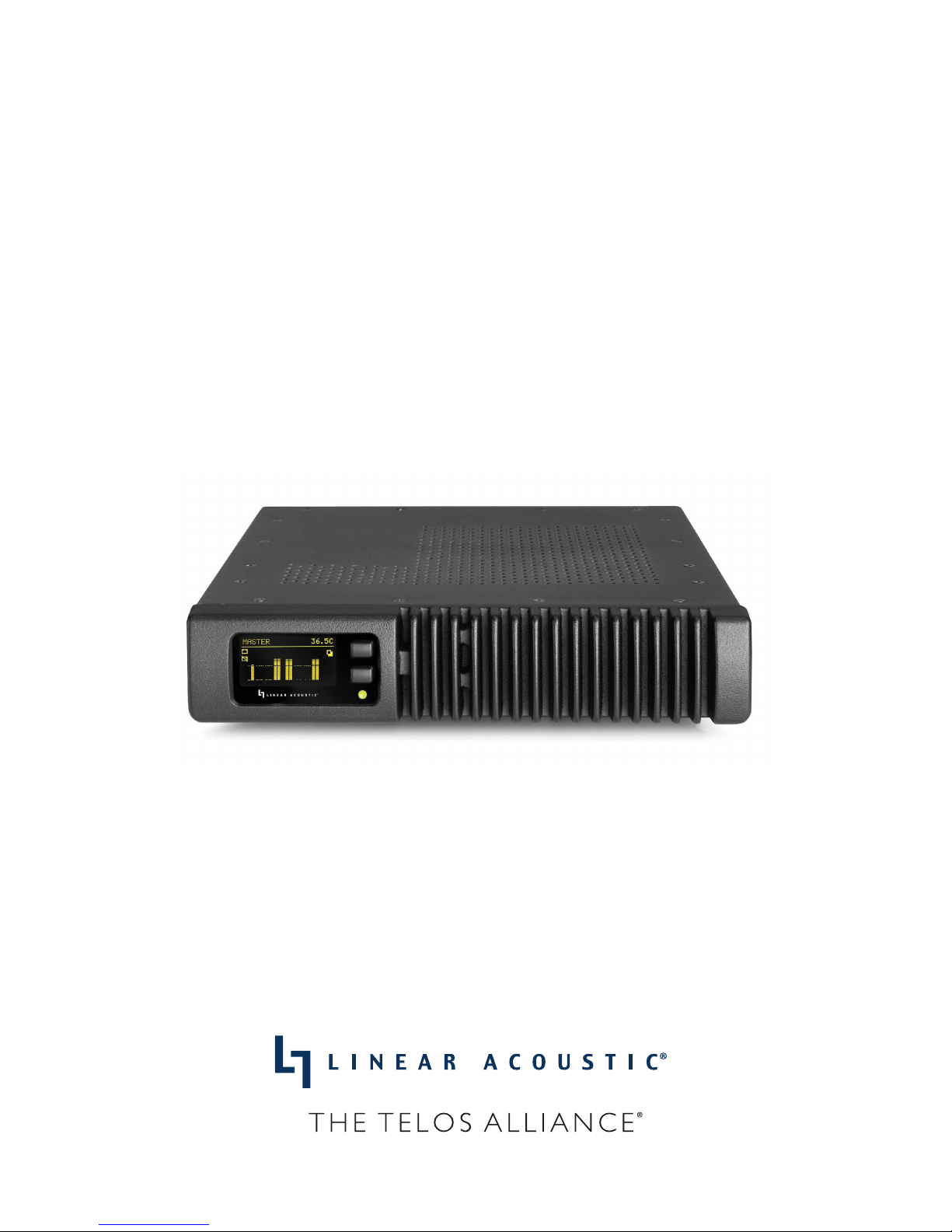
SDI XNODE
Livewire+/AES67 Audio over IP Interface with Dual HD/SD-SDI Ports
USER’S MANUAL
Manual for software version 1.6.4e
January 2019
TelosAlliance.com

II |
User Warnings and Cautions
The installation and service instructions in this manual are for use by qualied personnel only. To avoid
electric shock, do not perform any servicing other than that contained in the operating instructions unless
you are qualied to do so. Refer all servicing to qualied personnel
This instrument has an autoranging line voltage input. Ensure the power voltage is within the specied
range of 100-240VAC. The ~ symbol, if used, indicates an alternating current supply.
This symbol, wherever it appears, alerts you to the presence of uninsulated, dangerous voltage inside
the enclosure – voltage which may be sufcient to constitute a risk of shock.
This symbol, wherever it appears, alerts you to important operating and maintenance instructions.
Read the manual.
CAUTION: HAZARDOUS VOLTAGES
The instrument power supply incorporates an internal fuse. Hazardous voltages may still be present on
some of the primary parts even when the fuse has blown. If fuse replacement is required, replace fuse only
with same type and value for continued protection against re.
WARNING:
The product’s power cord is the primary disconnect device. The socket outlet should be located near the
device and easily accessible. The unit should not be located such that access to the power cord is impaired.
If the unit is incorporated into an equipment rack, an easily accessible safety disconnect device should be
included in the rack design.
To reduce the risk of electrical shock, do not expose this product to rain or moisture. This unit is for indoor
use only.
This equipment requires the free ow of air for adequate cooling. Do not block the ventilation openings
on the rear and sides of the unit. Failure to allow proper ventilation could damage the unit or create a re
hazard. Do not place the units on a carpet, bedding, or other materials that could interfere with any panel
ventilation openings.
If the equipment is used in a manner not specied by the manufacturer, the protection provided by the
equipment may be impaired.
USA CLASS A COMPUTING DEVICE INFORMATION TO USER.
WARNING:
This equipment generates, uses, and can radiate radio-frequency energy. If it is not installed and used as
directed by this manual, it may cause interference to radio communication. This equipment complies with
the limits for a Class A computing device, as specied by FCC rules, part 15, subpart j, which are designed
to provide reasonable protection against such interference when this type of equipment is operated in a
commercial environment. Operation of this equipment in a residential area is likely to cause interference.
If it does, the user will be required to eliminate the interference at the user’s expense. Note: objectionable
interference to TV or radio reception can occur if other devices are connected to this device without the use
of shielded interconnect cables. FCC rules require the use of shielded cables.

| III
CANADA WARNING:
“This digital apparatus does not exceed the Class A limits for radio noise emissions set out in the radio
interference regulations of the Canadian department of communications.”
“Le présent appareil numérique n’émet pas de bruits radioélectriques dépassant les limites applicables aux
appareils numériques (de Class A) prescrites dans le règlement sur le brouillage radioélectrique édicté par le
ministère des communications du Canada.”
CE CONFORMANCE INFORMATION:
This device complies with the requirements of the EEC council directives:
♦93/68/EEC (CE MARKING)
♦73/23/EEC (SAFETY – LOW VOLTAGE DIRECTIVE)
♦89/336/EEC (ELECTROMAGNETIC COMPATIBILITY)
Conformity is declared to those standards: EN50081-1, EN50082-1.
Trademarks, Patents, and Licenses
Linear Acoustic is a trademark of TLS Corp. All other trademarks are the property of their respective holders.
All versions, claims of compatibility, trademarks, etc. of hardware and software products not made by The
Telos Alliance which are mentioned in this manual or accompanying material are informational only. The Telos
Alliance makes no endorsement of any particular product for any purpose, nor claims any responsibility for
operation or accuracy. We reserve the right to make improvements or changes in the products described in this
manual which may affect the product specications, or to revise the manual without notice.
This document and its content are copyrighted by TLS Corporation and may not be copied, reproduced, or
distributed in any form without expressed written permission.
Patent information can be found at www.TelosAlliance.com/legal
Updates
Linear Acoustic SDI xNode features and operations are determined largely by software. The Telos Alliance
strives to provide the most stable and feature-rich software available. We encourage you to check for software
updates from time to time by visiting our website or by contacting us directly.
Feedback
We welcome feedback on any aspect of our products or this manual. In the past, many good ideas from users have
made their way into software revisions or new products. Please contact us with your comments or suggestions.

IV |
We support you…
By Phone/Fax
You may reach our Telos Support Team in emergencies by calling +1 216-622-0247. For billing questions
or other non-emergency technical questions, call +1 216-241-7225 between 9:00 AM to 5:00 PM USA
Eastern Time, Monday through Friday.
By Email.
Non-emergency technical support is available at Support@TelosAlliance.com.
By Web
The Linear Acoustic Web site has a variety of information that may be useful for product selection and
support. The URL is https://www.telosalliance.com/Linear .
SERVICE
You must contact Telos Alliance before returning any equipment for factory service. We will need your
unit’s serial number, located on the back of the unit. We will issue a return authorization number, which
must be written on the exterior of your shipping container. Please do not include cables or accessories
unless specically requested by the Technical Support Engineer. Be sure to adequately insure your
shipment for its replacement value. Packages without proper authorization may be refused. US customers,
please contact Telos Alliance Technical Support at +1-216-622-0247. All other customers should contact
local representative to make arrangements for service.
Warranty
For the latest Telos Alliance warranty, visit: telosalliance.com/warranty
Register your product
Register your product today to get the full benets of our warranty, support, and product updates.
telosalliance.com/product-registration/
The Telos Alliance
1241 Superior Ave. Cleveland, OH 44114 USA
+1 (216) 241-7225
For Telos Support:
24/7 telephone: +1 (216) 622-0247
Email: [email protected]
Web: telosalliance.com/support-request

| VV | Table of Contents
1 Introduction 1
Introduction . . . . . . . . . . . . . . . . . . . . . . . . . . . . . . . . 1
xNode Family . . . . . . . . . . . . . . . . . . . . . . . . . . . . . . 1
About Livewire+ . . . . . . . . . . . . . . . . . . . . . . . . . . . . . . 2
Warranty and Feedback . . . . . . . . . . . . . . . . . . . . . . . . . . . 3
2 Overview and Connections 4
Unpacking and Inspection . . . . . . . . . . . . . . . . . . . . . . . . . . 4
Unit Overview . . . . . . . . . . . . . . . . . . . . . . . . . . . . . . . 4
Block diagram. . . . . . . . . . . . . . . . . . . . . . . . . . . . . . 4
Front panel . . . . . . . . . . . . . . . . . . . . . . . . . . . . . . . 5
Rear panel . . . . . . . . . . . . . . . . . . . . . . . . . . . . . . . 6
Connections . . . . . . . . . . . . . . . . . . . . . . . . . . . . . . . . 6
Rear Panel . . . . . . . . . . . . . . . . . . . . . . . . . . . . . . . 6
AC Power Connection . . . . . . . . . . . . . . . . . . . . . . . . . . 7
Backup Power Connection . . . . . . . . . . . . . . . . . . . . . . . . 7
Network Connections . . . . . . . . . . . . . . . . . . . . . . . . . . 7
SDI Input . . . . . . . . . . . . . . . . . . . . . . . . . . . . . . . . 7
SDI Output . . . . . . . . . . . . . . . . . . . . . . . . . . . . . . . 7
Installation and Mounting . . . . . . . . . . . . . . . . . . . . . . . . . . 7
Installation . . . . . . . . . . . . . . . . . . . . . . . . . . . . . . . 7
Mounting. . . . . . . . . . . . . . . . . . . . . . . . . . . . . . . . 7
Rack Mount kit . . . . . . . . . . . . . . . . . . . . . . . . . . . . . 8
Front Panel Displays and Indicators . . . . . . . . . . . . . . . . . . . . . . 10
Power and Status LED . . . . . . . . . . . . . . . . . . . . . . . . . .10
Home Screen . . . . . . . . . . . . . . . . . . . . . . . . . . . . . . 10
Audio Meters Source/Destination 1-4 . . . . . . . . . . . . . . . . . . .11
Audio Meters Source/Destination 5-8 . . . . . . . . . . . . . . . . . . .11
SDI Input Format . . . . . . . . . . . . . . . . . . . . . . . . . . . .12
xNode ID Screen . . . . . . . . . . . . . . . . . . . . . . . . . . . . . 12
IP Address and Subnet Mask . . . . . . . . . . . . . . . . . . . . . . .13

VI | SDI xNode | VI
3 Initial Conguration 14
Unit Conguration . . . . . . . . . . . . . . . . . . . . . . . . . . . . .14
Fast Setup . . . . . . . . . . . . . . . . . . . . . . . . . . . . . . .14
Assigning an IP address manually . . . . . . . . . . . . . . . . . . . . . 16
Assigning an ID . . . . . . . . . . . . . . . . . . . . . . . . . . . . . 16
iProbe conguration . . . . . . . . . . . . . . . . . . . . . . . . . . . 17
Web interface conguration (“Simple setup”) . . . . . . . . . . . . . . .18
Factory Reset / Restoring Defaults . . . . . . . . . . . . . . . . . . . . . 18
4 Web Interface 19
Interface . . . . . . . . . . . . . . . . . . . . . . . . . . . . . . . . . . 19
System Option Pages . . . . . . . . . . . . . . . . . . . . . . . . . . . . 19
Home Page . . . . . . . . . . . . . . . . . . . . . . . . . . . . . . . 19
Simple Setup Page . . . . . . . . . . . . . . . . . . . . . . . . . . . . . 21
Unicast Link Page . . . . . . . . . . . . . . . . . . . . . . . . . . . . . . 22
Advanced Options Pages . . . . . . . . . . . . . . . . . . . . . . . . . .25
Sources Page . . . . . . . . . . . . . . . . . . . . . . . . . . . . . . 25
Destination Page . . . . . . . . . . . . . . . . . . . . . . . . . . . . . . 27
SDI I/O Page . . . . . . . . . . . . . . . . . . . . . . . . . . . . . . . . 29
Meter Page . . . . . . . . . . . . . . . . . . . . . . . . . . . . . . . .30
Synchronization and QoS Page . . . . . . . . . . . . . . . . . . . . . . . . 31
System Page . . . . . . . . . . . . . . . . . . . . . . . . . . . . . . . . 33
5 AES67 Features 35
AES67 . . . . . . . . . . . . . . . . . . . . . . . . . . . . . . . . . . . 35
Network Synchronization Setup . . . . . . . . . . . . . . . . . . . . . . .35
AES67 Multicast Connection Setup . . . . . . . . . . . . . . . . . . . . . . 36
AES67 Unicast Setup . . . . . . . . . . . . . . . . . . . . . . . . . . . .37

| VIIVII | Table of Contents
6 Conguration Example 39
Introduction . . . . . . . . . . . . . . . . . . . . . . . . . . . . . . . . 39
SDI In to Livewire+ Source . . . . . . . . . . . . . . . . . . . . . . . . . . 40
Livewire+ Destinations . . . . . . . . . . . . . . . . . . . . . . . . . . . 42
SDI Output Embedding . . . . . . . . . . . . . . . . . . . . . . . . . . .43
7 Specications 44
Physical . . . . . . . . . . . . . . . . . . . . . . . . . . . . . . . . . . 44
Electrical . . . . . . . . . . . . . . . . . . . . . . . . . . . . . . . . . . 45
Audio . . . . . . . . . . . . . . . . . . . . . . . . . . . . . . . . . . .46
Other . . . . . . . . . . . . . . . . . . . . . . . . . . . . . . . . . . .46
8 Telos Alliance Warranty 47


Creating the Most Exciting and Engaging
Audio Experiences Imaginable
Congratulations on your new Telos Alliance product!
The gang here at Telos is committed to shaping the future of audio by delivering innovative, intuitive
solutions that inspire our customers to create the most exciting and engaging audio experiences imaginable.
We’re grateful that you have chosen audio tools from Telos® Systems, Omnia® Audio, Axia® Audio,
Linear Acoustic®, 25-Seven Systems®, and Minnetonka Audio®. We’re here to help you make your work
truly shine. We hope that you enjoy your Telos Alliance product for many years to come and won’t hesitate
to let us know if we can help in any way.
The Telos Alliance

1 Introduction
Introduction
Congratulations on your purchase of the Linear Acoustic SDI xNode. The SDI xNode is a compact and powerful
HD/SD-SDI to Livewire+/AES-67 Audio over IP interface. It is capable of managing dual, independent HD/SD-
SDI paths and can de-embed, shuffle, and re-embed up to 16 channels of audio in an SDI path.
The SDI xNode features:
♦Two HD/SD-SDI inputs and outputs with compensating video delay.
♦de-embed up to 16-channels of audio from SDI and output them across a Livewire+/AES67 (AoIP)
network.
♦Receive up to 16-channels of audio from a Livewire+ network and embed them into one or two SDI
streams.
♦Autoranging power supply plus input for a back-up power supply.
♦Network configuration, control, and monitoring
Includes all standard xNode controls including front panel and web interface.
The SDI xNode provides up to 16-channels of audio to the Livewire+ network (called a Livewire+ “Source”) and
receives up to 16-channels of audio from the Livewire+ network (Livewire+ “Destination”).
xNode Family
The xNodes are a family of compact 1U high, one-half space wide Livewire+ audio and logic interfaces with
advanced features. Many of the xNode models are offered by Axia Audio, one of our sister companies in the Telos
Alliance.
Livewire+ is a patented AoIP protocol, developed by Axia Audio, which enables high-reliability, low-delay uncom-
pressed digital audio over a standard Ethernet network.
xNodes are fully AES67 compliant, and include support for Ravenna stream routing and IEEE 1588 synchroniza-
tion.
All xNodes, including the SDI xNode, include dual 100BT Ethernet ports which are user configurable as either
mirroring redundant ports or as a single Livewire+ port and separate management port.
A front panel OLED display for setup and status is included, along with a http server for full configuration, control,
and monitoring from a web browser.

2| Section 1
Other members of the xNode family, which are oered by Axia Audio, include:
Analog xNode:
4 Stereo Analog Line level Inputs, 4 Stereo Analog Line-level Outputs
AES/EBU xNode:
4 Stereo Digital AES-3 Inputs, 4 Stereo Digital AES-3 Outputs
Microphone xNode:
4 Mic Inputs, 4 Stereo Analog Line-level Outputs
GPIO Logic xNode:
6 GPIO Ports, each with 5 optically isolated inputs and 5 optically isolated outputs
Mixed Signal xNode:
1 Mic/Line Analog Input
2 Analog Line Inputs
1 AES-3 Input
3 Analog Line Outputs
1 AES-3 Output
2 GPIO Ports, each with 5 inputs and 5 outputs.
xSelector:
Includes Livewire+ I/O, Analog, and AES-3 I/O along with a Headphone output. Six “radio buttons” allow instant
monitoring of favorite sources.
xSwitch:
The world’s only zero-configuration Ethernet switch optimized for Livewire+. Features eight (8) 100BT Ethernet
ports, along with two (2) 1000BT ports for trunking. 1000BT ports include both RJ-45 and SFP fiber connections.
About Livewire+
This manual covers the details of the SDI xNode. To learn more about Livewire+ and AoIP, you may wish to read
Introduction to Livewire+: System Design Reference and Primer which is available on the Telos Alliance website
(www.telosalliance.com) and Audio Over IP: Building Pro AoIP Systems with Livewire+ by Steve Church and Skip
Pizzi, available from Elsevier Press.
In these publications we explain the ideas that motivated Livewire+ and how you can use and benefit from it, as
well as nitty-gritty details about wiring, connectors, and the like. Since Livewire+ is built on standard networks,
we also help you to understand general network engineering so that you have the full background for Livewire+’s
fundamentals.

3| Section 1
Warranty and Feedback
For the latest Telos Alliance warranty, visit: telosalliance.com/warranty.

2 Overview and Connections
Unpacking and Inspection
Before unpacking the unit, inspect the outer carton for shipping damage. If the carton shows damage, inspect the
unit in those areas. Please save the carefully designed shipping carton and packing materials. In the unlikely event
that the unit needs to be returned to the factory, alternate cartons or packing materials may not be adequate and can
cause damage not covered by warranty.
The following essential items are provided with the unit:
♦IEC power cord (style matches country of order)
♦Quick-start sheet to get you up and running
♦USB memory stick containing documentation, including this manual
♦rack mount hardware kit
♦a handy black pen.
Unit Overview
This section introduces you to SDI xNode and its views:
Block diagram
The SDI xNode is capable of:
♦handling two independent SDI streams
♦de-embedding up to 16-channels of audio from SDI input stream(s) and outputting them onto a
Livewire+/AES67 AoIP network
♦receiving up to 16-channels of audio from a Livewire+ network and embedding them into the SDI output
stream(s)
♦pass-through of input SDI audio and pair shuffling to the SDI output
♦compensating video delay of up to 1 second for each SDI stream

5| Section 2
The block diagram of the SDI xNode is shown below:
Figure 1 - SDI xNode Block Diagram
Front panel
On the front panel of the SDI xNode, you will find:
♦OLED display
♦Two pushbutton switches for:
◊ Display page selection (Screen button)
◊ Edit Mode selection (Pencil button)
♦Power LED
The OLED display provides the user with visual feedback and interaction as to what the SDI xNode is doing,
parameter settings, and input signal status.
Figure 2 - SDI xNode front panel

6| Section 2
A closer view of the front panel and controls is provided below:
Figure 3 - SDI xNode display and controls
Rear panel
The rear panel of the SDI xNode is where all connections are made.
The rear panel includes:
♦Power inlets
♦Two 100 BT Ethernet ports
♦Two 75-ohm BNC connectors for SDI inputs
♦Two 75-ohm BNC connectors for SDI outputs
Connections
This section covers all connections
Rear Panel
The rear panel of the SDI xNode contains the connections which will be used.
Figure 4 - SDI xNode Rear Panel

7| Section 2
AC Power Connection
An IEC universal power inlet is provided. This accepts an AC input from 95v up through 240v, at either 50 or 60 Hz.
Backup Power Connection
A 12VDC power connector is provided for a redundant, or back-up, power supply.
Network Connections
Two 100BT Ethernet ports are provided. They are configurable as either mirroring redundant ports or as a single
Livewire+ port and separate management port.
To be precise, the mode of the Ethernet ports when configured as redundant ports is called “active-passive Ethernet
port bonding”. In active-passive mode, only one port is used, and the other one is a fail-over backup.
SDI Input
Two autosensing SD/HD-SDI input connectors are included on the SDI xNode.
All 16-channels of an SDI stream are available for de-embedding, embedding, and pair shuffling.
SDI Output
Two SD/HD-SDI output connections are included on the rear of the SDI xNode. All 16 audio channels in the SDI
stream are available for embedding and pair shuffling.
Installation and Mounting
Installation
The xNode is a fanless device, so it may be located in a control room or other location where fan noise cannot
be tolerated. Because this unit is passively cooled, it is recommended to leave an empty space above the unit
when mounted in a rack or other enclosure. An internal thermal sensor is designed in to the product, so that the
operating temperature of the xNode may be monitored remotely
Mounting
The SDI xNode includes a rack mounting kit. The mounting hole location and pattern is consistent with all
xNodes, so any xNode may be mounted using the available kit, and two of them may be mounted side by side.
8| Section 2
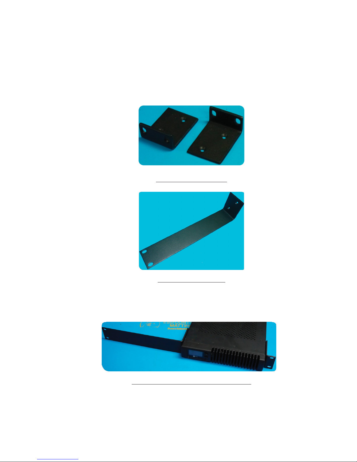
Rack Mount kit
The rack mount kit provides the ability to secure the xNode into an equipment rack. The kit contains two short
rack ears, one long rack ear, and a spacer plate.
Figure 5 - Short rack mount ears
Figure 6 - Long rack mount ear
Single xNode
To rack mount a single xNode, secure the short rack ear to one side of the xNode and secure the long ear to the
opposing side of the xNode.
Figure 7 - xNode with long and short rack ear installed

9| Section 2
Two xNodes
It is possible to install two xNodes in a side-by-side configuration. The mounting hole locations and pattern are
consistent with all xNodes, so any xNode may be mounted next to the SDI xNode.
To mount two units side by side:
Remove the top lid from both xNodes. Place two xNodes side by side. Place the spacer plate between the two xNodes
Figure 8 - Spacer plate in between two xNodes, top view
Use the four (4) screws provided to secure the two nodes together.
Figure 9 - Spacer plate in between two xNodes, angled view
Replace the lids on the xNodes. Secure the short rack ears to either side of the two xNodes
10 | Section 2
Front Panel Displays and Indicators
The front panel OLED provides several different status and configuration screens, along with the Power and Status
LED. The description and definition of those displays are below.
Power and Status LED
The Power LED located on the front panel is a multicolor LED and changes its color to indicate the status of the
power source(s) applied to the SDI xNode.
Color Description
Green Powered by the primary AC Mains power supply (IEC inlet)
Yellow Powered by both AC Mains and redundant power input
Red Powered by external 12 VDC redundant power
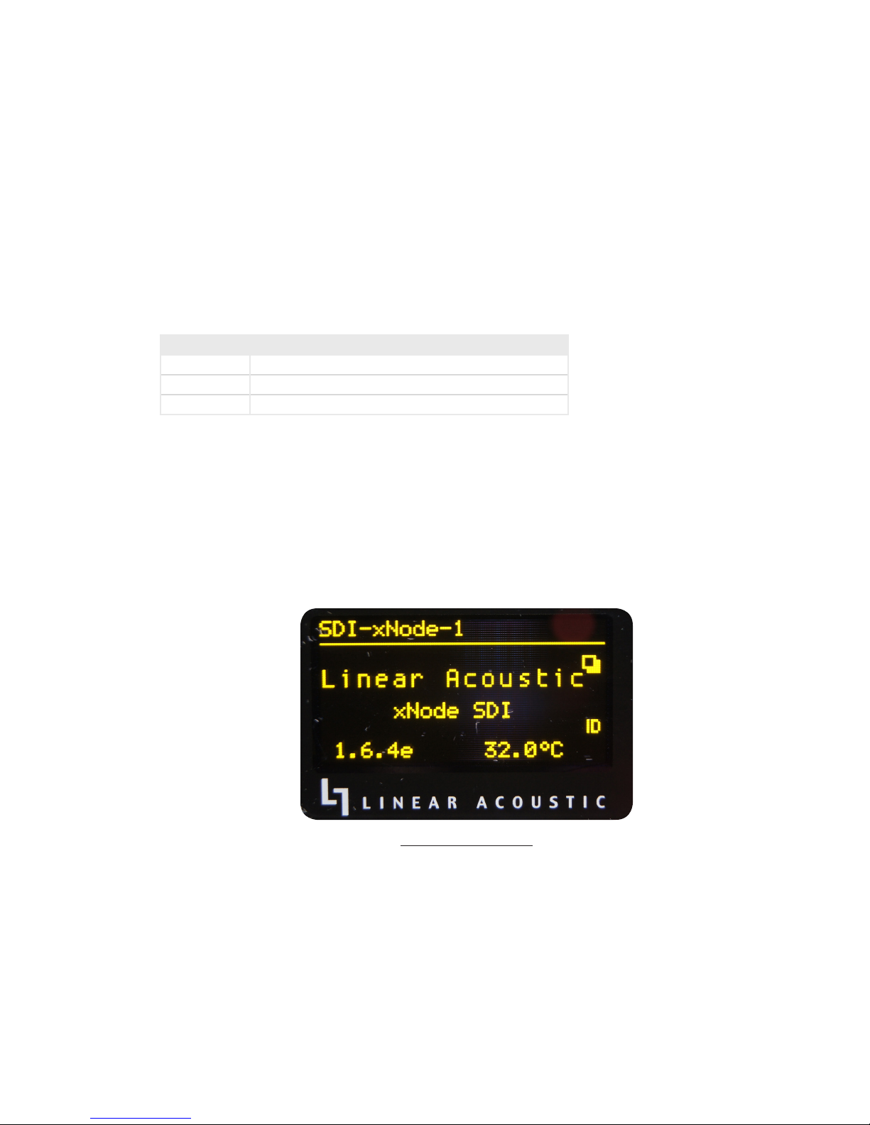
Home Screen
The initial screen displayed after boot up is this home screen. It identifies the unit as the SDI xNode, the software
version in use, and the internal temperature of the unit. After approximately 20 seconds, the display will change
over to the Audio Meter display for Source/Destination 1 – 4.
Figure 10 - Home Screen

11 | Section 2
Audio Meters Source/Destination 1-4
Audio meters for Sources 1-4 and Destinations 1-4 are provided. Sources 1-4 are shown on the left, and Destina-
tions 1-4 are shown on the right.
Figure 11 – Meters for I/O pairs 1 - 4
Audio Meters Source/Destination 5-8
Audio meters for Sources 5-8 and Destinations 5-8 are provided. Sources are shown on the left, and Destinations
are shown on the right
Figure 12 - Meters for I/O pairs 5 - 8
Table of contents
Other Telos Alliance Recording Equipment manuals


