Club Weider WESY49201 User manual
QUESTIONS?
As a manufacturer, we are com-
mitted to providing complete
customer satisfaction If you
have questions, or find that there
are missing or damaged parts,
we will guarantee you complete
satisfaction through direct assis-
tance from our factory
TO AVOID UNNECESSARY
DELAYS, PLEASE CALL DIRECT
TO OUR TOLL-FREE CUSTOMER
HOT LINE The trained techni-
cians on our customer hot line
will provide immediate assis-
tance, free of charge to you
CUSTOMER HOT LINE:
1-800-999-3756
Mon –Fri , 6 a m –6 p m MST
Model No WESY49201
Serial No
Write the serial number in the space
above for reference.
CAUTION
Read all precautions and instruc-
tions in this manual before using
this equipment Save this manu-
al for future reference
USER'S MANUAL
Serial Number Decal (Under Seat)
TABLE OF CONTENTS
IMPO TANT P ECAUTIONS . . . . . . . . . . . . . . . . . . . . . . . . . . . . .2
BEFO E YOU BEGIN . . . . . . . . . . . . . . . . . . . . . . . . . . . . . . . . . .3
ASSEMBLY . . . . . . . . . . . . . . . . . . . . . . . . . . . . . . . . . . . . . . . . . .4
ADJUSTMENTS . . . . . . . . . . . . . . . . . . . . . . . . . . . . . . . . . . . . . .22
WEIGHT ESISTANCE CHA T . . . . . . . . . . . . . . . . . . . . . . . . . .24
T OUBLE-SHOOTING AND MAINTENANCE . . . . . . . . . . . . . . . .25
CABLE DIAG AMS . . . . . . . . . . . . . . . . . . . . . . . . . . . . . . . . . . .26
O DE ING EPLACEMENT PA TS . . . . . . . . . . . . . . .Back Cover
LIMITED WA ANTY . . . . . . . . . . . . . . . . . . . . . . . . . .Back Cover
Note: A PA T IDENTIFICATION CHA T and a PA T LIST/
EXPLODED D AWING are attached in the center of this manual.
1 Read all instructions in this manual and in
the accompanying literature before using the
weight system
2 It is the responsibility of the owner to ensure
that all users of the weight system are ade-
quately informed of all precautions
3 The weight system is intended for home use
only Do not use the weight system in any
commercial, rental, or institutional setting
4 Use the weight system only on a level sur-
face Cover the floor beneath the weight sys-
tem to protect the floor
5 Make sure all parts are properly tightened
each time you use the weight system
Replace any worn parts immediately
6 Keep children under 12 and pets away from
the weight system at all times
7 Keep hands and feet away from moving parts
8 Always wear athletic shoes for foot protection
9 The weight system is designed to support a
a maximum user weight of 250 pounds
10 Always stand on the foot plate when per-
forming an exercise that could cause the
weight system to tip
11 Always disconnect the lat bar from the
weight system when performing an exercise
that does not use the lat bar.
12 Make sure that the cables remain on the pul-
leys at all times If the cables bind while you
are exercising, stop immediately and make
sure that the cables are on all of the pulleys
13 Never release the press arm, butterfly arms,
military press arm, leg lever, leg press plate,
lat bar or nylon strap when weights are
raised The weights will fall with great force
14 Keep your hands away from the assist
upright when the assist arm is being used
Your hand could become pinched between
the assist upright and the assist arm
15 Keep your hands away from the leg press
upright when the military press arm is being
used Your hand could become pinched
between the leg press upright and the mili-
tary press arm
16 Always be sure that your body weight is fully
supported by the dip arms or the pull-up
arms before kneeling on the assist arm The
assist arm can drop quickly when your body
weight is placed on it
17 If you feel pain or dizziness at any time while
exercising, stop immediately and begin cool-
ing down
18 The decals shown below have been placed
on the weight system in the locations shown
on page 3 If a decal is missing or illegible,
call our toll-free Customer Hot Line at
1-800-999-3756 and order a free replacement
decal Apply the decal in the location shown
2
WARNING:To reduce the risk of serious injury, read the following important precau-
tions before using the weight system
WARNING:Before beginning this or any exercise program, consult your physician This
is especially important for persons over the age of 35 or persons with pre-existing health problems
Read all instructions before using ICON assumes no responsibility for personal injury or property
damage sustained by or through the use of this product
Keep hands and
fingers clear of
this area.
• Keep clear of
this area
IMPORTANT PRECAUTIONS
Warning Decal 2
Warning Decal 1
Warning Decal 3
3
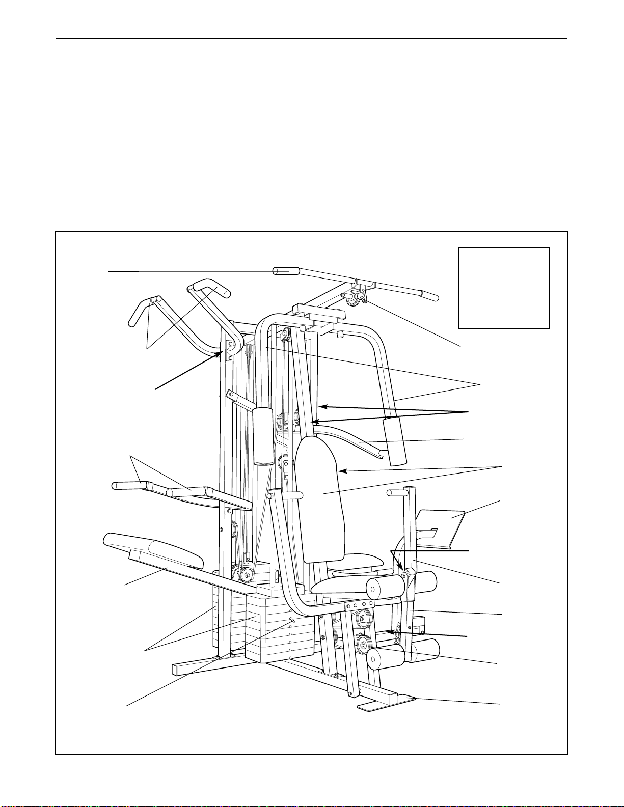
BEFORE YOU BEGIN
ASSEMBLED
DIMENSIONS:
Height: 78 in.
Width: 86 in.
Length: 66 in.
Foot Plate
High Pulley Station
Lat Bar
Leg Lever
Butterfly Arms
Assist Arm Press Arm
Weight Stacks
Backrests
Dip Handles
Pull-up Handles
Warning Decal 1
Warning Decal 1
Warning Decal 3
Warning Decal 2
Leg Press
Plate
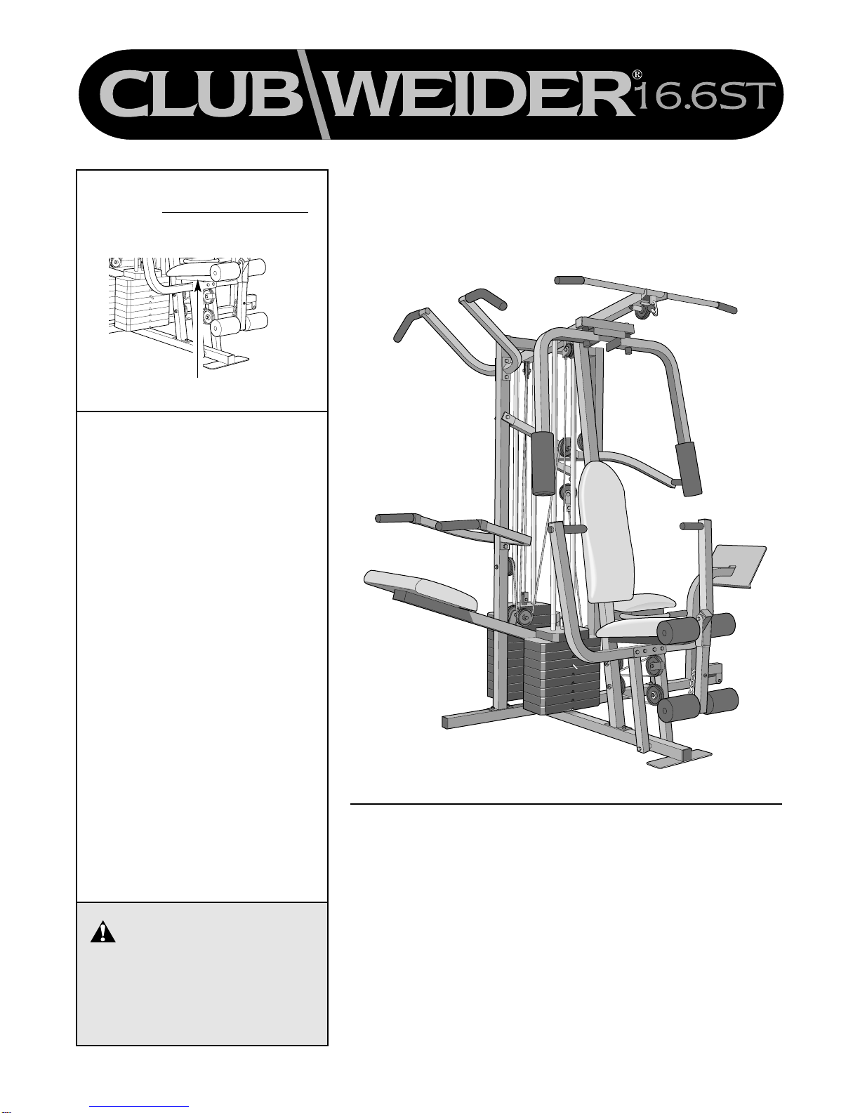
Thank you for selecting the versatile CLUB WEIDE ®
16.6ST weight system. The CLUB WEIDE ®16.6ST
offers a selection of weight stations designed to devel-
op every major muscle group of the body. Whether
your goal is to tone your body, build dramatic muscle
size and strength, or improve your cardiovascular sys-
tem, the CLUB WEIDE ®16.6ST will help you to
achieve the specific results you want.
For your benefit, read this manual carefully before
using the weight system If you have additional
questions, please call our Customer Service
Department toll-free at 1-800-999-3756, Monday
through Friday, 6 a.m. until 6 p.m. Mountain Time
(excluding holidays). To help us assist you, please note
the product model number and serial number before
calling. The model number is WESY49201. The serial
number can be found on a decal attached to the
weight system (see the front cover of this manual).
Before reading further, please review the drawing
below and familiarize yourself with the parts that are
labeled.
Weight Pin
Low Pulley
Station
Military Press Arm
4
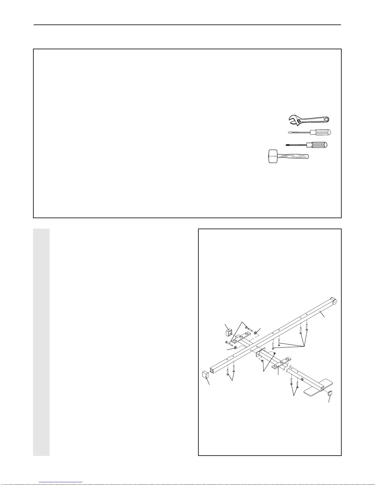
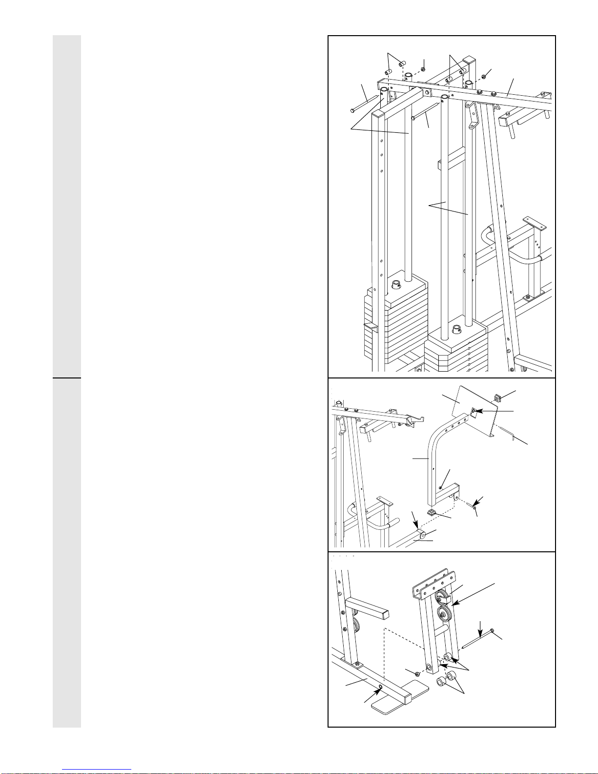
ASSEMBLY
1
8
8
11
51
27
1
4
3
1
51
5
1. Before beginning assembly, be sure that
you have read and understand the infor-
mation in the box above
Locate and open the parts bag labeled
“FRAME ASSEMBLY”
Press two 2” Square Outer Caps (51) onto
the Stabilizer (5). Press a 2” Square Inner
Cap (27) into the Base (4).
Insert six 5/16” x 2 1/2” Carriage Bolts (1) up
through the Stabilizer (5). Insert two 5/16” x 2
1/2” Carriage Bolts up through the Base (4).
Attach the Base (4) to the Stabilizer (5) with
two 5/16” x 2 3/4” Bolts (11), two 5/16”
Washers (8), and two 5/16” Nylon Locknuts
(3). Do not tighten the Nylon Locknuts yet
FRAME ASSEMBLY
Before beginning assembly, carefully read the
following information and instructions:
•Place all parts of the weight system in a cleared
area and remove the packing materials; do not
dispose of the packing materials until assembly is
completed.
• The assembly is broken into four stages: 1) frame
assembly, 2) arm assembly, 3) cable assembly,
and 4) seat and backrest assembly. The hard-
ware for each stage is packaged separately.
• Wait until you begin each assembly stage to open
the parts bag labeled for that assembly stage.
•For help identifying the small parts used in
assembly, use the PART IDENTIFICATION
CHART located in the center of this manual
Note: Some small parts may have been pre-
attached for shipping. If a part is not in the parts
bag, check to see if it has been pre-attached.
•As you assemble the weight system be sure that
all parts are oriented as shown in the drawings.
•Tighten all parts as you assemble them, unless
instructed to do otherwise.
THE FOLLOWING TOOLS (NOT INCLUDED) ARE
REQUIRED FOR ASSEMBLY:
• Two (2) adjustable wrenches
• One (1) standard screwdriver
• One (1) phillips screwdriver
• One (1) rubber mallet
• Lubricant, such as grease or petroleum jelly,
and soapy water will also be needed
Assembly will be more convenient if you have the
following tools: A socket set, a set of open-end or
closed-end wrenches, or a set of ratchet wrenches.
1

5
2. Slide the Assist Upright (74) and the Leg
Press Upright (56) onto the indicated 5/16” x
2 1/2” Carriage Bolts (1) in the Stabilizer (5).
The high side of the brackets on the Assist
Upright and Leg Press Upright should be
on the side shown Hand-tighten four 5/16”
Nylon Locknuts (3) onto the Carriage Bolts.
Do not tighten the Nylon Locknuts yet
Press a 2” Square Inner Cap (27) into the Leg
Press Upright (56). Press a 2” Square Inner
Cap into the Assist Upright (74).
Attach the ubber Bumper (91) to the Leg
Press Upright (56) with the #8 x 1/2” Self-tap-
ping Screw (87).
3. Slide the Front Upright (42) onto the 5/16” x
2 1/2” Carriage Bolts (1) in the Base (4).
Hand-tighten a 5/16” Nylon Locknut (3) onto
each Carriage Bolt. Do not tighten the
Nylon Locknuts yet
Press a 1” Square Inner Cap (6) into the
Front Upright (42).
2
27
27
1
1
56
74
33
3
35
High Sides
of Brackets
3
FRAME ASSEMBLY
42
6
4
1
3
87
91

6
4. Press a 2” Square Inner Cap (27) into the end
of the Top Frame (55). Press a 1 3/4” Square
Inner Cap (44) into each end of the crossbar
on the Top Frame. Press two 1” Inner Caps
(113) into the top of the crossbar.
Attach the Top Frame (55) to the Assist
Upright (74) and the Leg Press Upright (56)
with two 5/16” x 2 3/4” Bolts (11) and two
5/16” Nylon Locknuts (3).
Attach the Top Frame (55) to the Front
Upright (42) with two 5/16” x 2 3/4” Bolts (11),
two 5/16” Washers (8), and two 5/16” Nylon
Locknuts (3).
5. Slide the ear Seat Frame (100) onto the
indicated 5/16” x 2 1/2” Carriage Bolts (1) in
the Stabilizer (5). Hand-tighten two 5/16”
Nylon Locknuts (3) onto the Carriage Bolts.
Do not tighten the Nylon Locknuts yet
Attach the other end of the ear Seat Frame
(100) to the Leg Press Upright (56) with two
5/16” x 2 3/4” Bolts (11), two 5/16” Washers
(8), and two 5/16” Nylon Locknuts (3).
Attach the Handle (82) to the ear Seat
Frame (100) with two 5/16” x 2 1/2” Carriage
Bolts (1) and two 5/16” Nylon Locknuts (3).
Tighten all Nylon Locknuts used in steps
1–5
6. Set two Weight Bumpers (19) on the bracket
on the Base (4) as shown. Set two Weight
Bumpers (19) on the bracket on the Stabilizer
(5).
Stack ten Weights (25) onto the bracket on
the Stabilizer (5). Stack eight Weights onto
the bracket on the Base (4). Be sure that the
pin grooves are all on the same side of
each stack of Weights
Be careful not to tip either stack of
Weights (25) until step 8 is complete
4
27
55
3
3
8
113
44
44
11
11
56 42
Crossbar
51
1
11
82
100
5
56
8
3
3
3
25 25
5
19
19
Bracket
4—Bracket
FRAME ASSEMBLY
74
Pin
Grooves
6Pin
Grooves

7
7. Press a Weight Tube Bumper (64) into the
end of the Short Weight Tube (108). Insert the
Weight Tube into the front stack of Weights
(25). Be sure that the pin on the Weight
Tube is sitting in the pin groove in the top
Weight
Lubricate the inside of the holes in a Top
Weight (65). Set the Top Weight onto the front
stack of Weights (25). Insert both Long
Weight Guides (62) into the stack of Weights.
Be sure that the holes in the Weight
Guides are at the top, as shown
8. Press a Weight Tube Bumper (64) into the
end of the Long Weight Tube (63). Insert the
Weight Tube into the rear stack of Weights
(25). Be sure that the pin on the Weight
Tube is sitting in the pin groove in the top
Weight
Lubricate the inside of the holes in the other
Top Weight (65). Set the Top Weight onto the
rear stack of Weights (25). Insert both Short
Weight Guides (73) into the stack of Weights.
Be sure that the holes in the Weight
Guides are at the top, as shown
7Holes
Lubricate
62
65
Pin
108
64
Pin Groove
Holes
Lubricate
73
65
Pin
63
64
Pin Groove
25
25
8
FRAME ASSEMBLY
8
9. Attach the upper ends of the Short Weight
Guides (73) to the Top Frame (55) with a 5/16”
x 6” Bolt (60), two 1/2” x 3/4” Spacers (61), and
a 5/16” Nylon Locknut (3).
Attach the upper ends of the Long Weight
Guides (62) to the Top Frame (55) in the same
manner.
10. Locate and open the parts bag labeled
“ARM ASSEMBLY”
Make sure there is a Bushing (98) in each side
of the Stabilizer (5). Press a 2” Square Inner
Cap (27) into each end of the Leg Press Arm
(96).
Lubricate a 3/8” x 3 1/4” Bolt (67). Attach the
Leg Press Arm (96) to the Stabilizer (5) with the
Bolt and a 3/8” Nylon Locknut (21). Do not over-
tighten the Nylon Locknut; the Leg Press
Arm must be able to pivot freely
Align the welded tubes on the Leg Press Plate
(95) with a set of holes in the Leg Press Arm
(96). Attach the Leg Press Plate to the Leg
Press Arm with the Press Pin (97).
11. Press a 1” x 7/8” Plastic Bushing (90) onto
each welded spacer on the Press Frame (17).
Slide the Press Frame into place onto the Base
(4). Note: This will be a tight fit; the Plastic
Bushings should fit snuggley over the ends
of the indicated tube in the Base Make sure
that the pulleys are on the side shown
Lubricate the 3/8” x 8” Bolt (59). Attach the
Press Frame (17) to the Base (4) with the Bolt
and a 3/8” Nylon Locknut (21).
11
17 Pulleys
must be on
this side
Lubricate
Welded Spacers
21
4
Tube 90
59
9
10
FRAME ASSEMBLYARM ASSEMBLY
61 61
33
60
73
62
55
27
Welded
Tube
27 67
96 21
Lubricate
97
5
98
98
95
60

9
12. Press a 1” ound Inner Cap (49) into one of
the Press Arms (46). Press a 1 3/4” Square
Inner Cap (44) into the Press Arm.
Attach the Press Arm (46) to one side of the
Press Frame (17) with two 5/16” x 2 1/2” Bolts
(22) and two 5/16” Nylon Locknuts (3).
Assemble the other Press Arm (46) in the
same manner.
13. Identify the ight Arm (48) and the Left Arm
(47). Note the position of the welded bracket
on each Arm. Arm identification is very
important for step 14
Attach a “V”-Pulley (50) and a Long Cable
Trap (31) to the ight Arm (48) with a 3/8” x
2 1/2” Bolt (86) and a 3/8” Nylon Locknut (21).
Do not tighten the Nylon Locknut yet
Attach a “V”-Pulley (50) and a Long Cable
Trap (31) to the Left Arm (47) in the same
manner.
14. Lubricate both axles on the Top Frame (55).
Slide the ight Arm (48) onto the right axle.
Note: Be careful not to confuse the Right
Arm with the Left Arm (47); refer to step 13
to identify the Right Arm Be sure that the
upper end of the Right Arm is behind the
indicated bracket on the Top Frame (55)
Tap two 1” etainers (69) and a 1” ound
Cover Cap (70) onto the axle. Be sure that
the teeth on the Retainers bend toward the
Round Cover Cap, as shown in the inset
drawing
Attach the Left Arm (47) in the same manner.
Press 1 3/4” Square Inner Caps (44) into the
lower ends of the ight and Left Arms (47,
48). Wet the lower end of each Arm with
soapy water. Slide a 10” Pad (45) onto the
lower end of each Arm.
12
13 86
31
31
50
50
21
Welded
Brackets
48
47
ARM ASSEMBLY
44 49
46
46
17
22
3
55 Bracket
Lubricate
Axle
47
69
70
44
45
44
14
69
70
Axle
45
48

10
15. See the inset drawing Attach the Military
Press Arm (84) to the Pivot Arm (101) with
two 5/16” x 2 1/4” Bolts (33) and two 5/16”
Nylon Locknuts (3).
Press two 1 1/2” Square Inner Caps (32) into
the Military Press Arm (84). Press two 1”
ound Inner Caps (49) into the Military Press
Arm.
Attach the Pivot Arm (101) to the Assist
Upright (74) with a 3/8” x 3 1/4” Bolt (67) and
a 3/8” Nylon Locknut (21).
16. Press two 1” x 2” Inner Caps (107) into the
Assist Arm (105).
Attach the Assist Arm (105) to the Leg Press
Upright (56) with a 3/8” x 6” Bolt (106), two
3/8” Washers (9), and a 3/8” Nylon Locknut
(21). See the inset drawing The Assist
Arm must be attached to the lowest hole in
the Leg Press Upright (56) The Assist Arm
must also be below the welded bracket on
the Assist Upright (74)
15
49 49 32
84
84
101
101
21
67
5674
33
3
ARM ASSEMBLY
32
16
107
106
105
105
Bracket
56
56
21
9
9
74
74
11
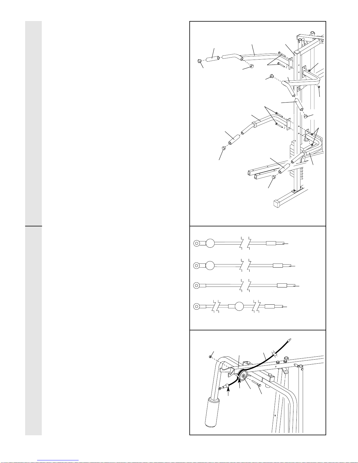
17. Attach the Left Pull-up Arm (75) and the ight
Pull-up Arm (77) to the Assist Upright (74)
with two 5/16” x 2 3/4” Bolts (11) and two
5/16” Nylon Locknuts (3).
Attach the Left Dip Arm (78) and the ight Dip
Arm (79) to the Assist Upright (74) with two
5/16” x 2 3/4” Bolts (11) and two 5/16” Nylon
Locknuts (3).
Wet the end of the Left Pull-up Arm (75) with
soapy water. Slide a Long Handgrip (80) onto
the Left Pull-up Arm.
Slide a Long Handgrip (80) onto the ight
Pull-up Arm (77), onto the Left Dip Arm (78),
and onto the ight Dip Arm (79) in the same
manner.
Press two 1 1/4” ound Inner Caps (109) into
the Left Pull-up Arm (75) and into the ight
Pull-up Arm (77).
Press a 1 1/4” ound Inner Cap (109) into the
Left Dip Arm (78), and into the ight Dip Arm
(79).
18. Locate and open the parts bags labeled
“CABLE ASSEMBLY” and “PULLEYS ”
During steps 19 through 39, refer to the
CABLE DIAG AMS on pages 26–27 of this
manual to verify proper cable routing. Before
beginning this section, fully unwind the four
Cables. Identify the four Cables by comparing
the lengths and ends of the Cables. The
approximate length of each Cable is listed
after the key number in the drawing.
IMPORTANT: While assembling the cables,
do not overtighten the bolts and nuts
attaching the pulleys The pulleys must be
able to turn freely
19. Locate the High Cable (58) Wrap the High
Cable around a 3 1/2” Pulley (15). Attach the
Pulley to the Top Frame (55) with a 3/8” x
3 3/4” Bolt (88) and a 3/8” Nylon Locknut (21).
Be sure that the end of the Cable with the
ball is on the indicated side of the Pulley
and that the Cable is between the Pulley
and the hook
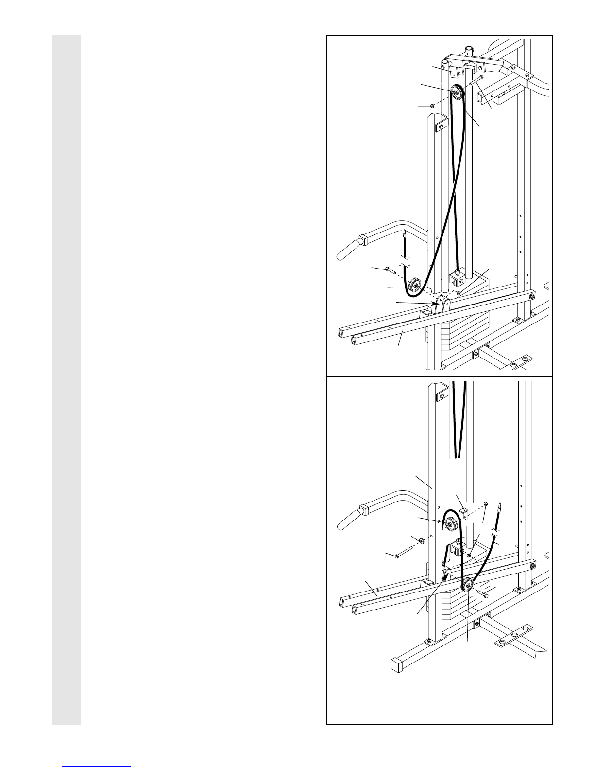
19
55
21 58
BallHook
17
75 74
78
18
23—75.5”
58—148”
72—190”
99—64”
ARM ASSEMBLYCABLE ASSEMBLY
11
109 109 109
109
109
11
77
80
80
80
80
3
3
3
15 88
109
79
12
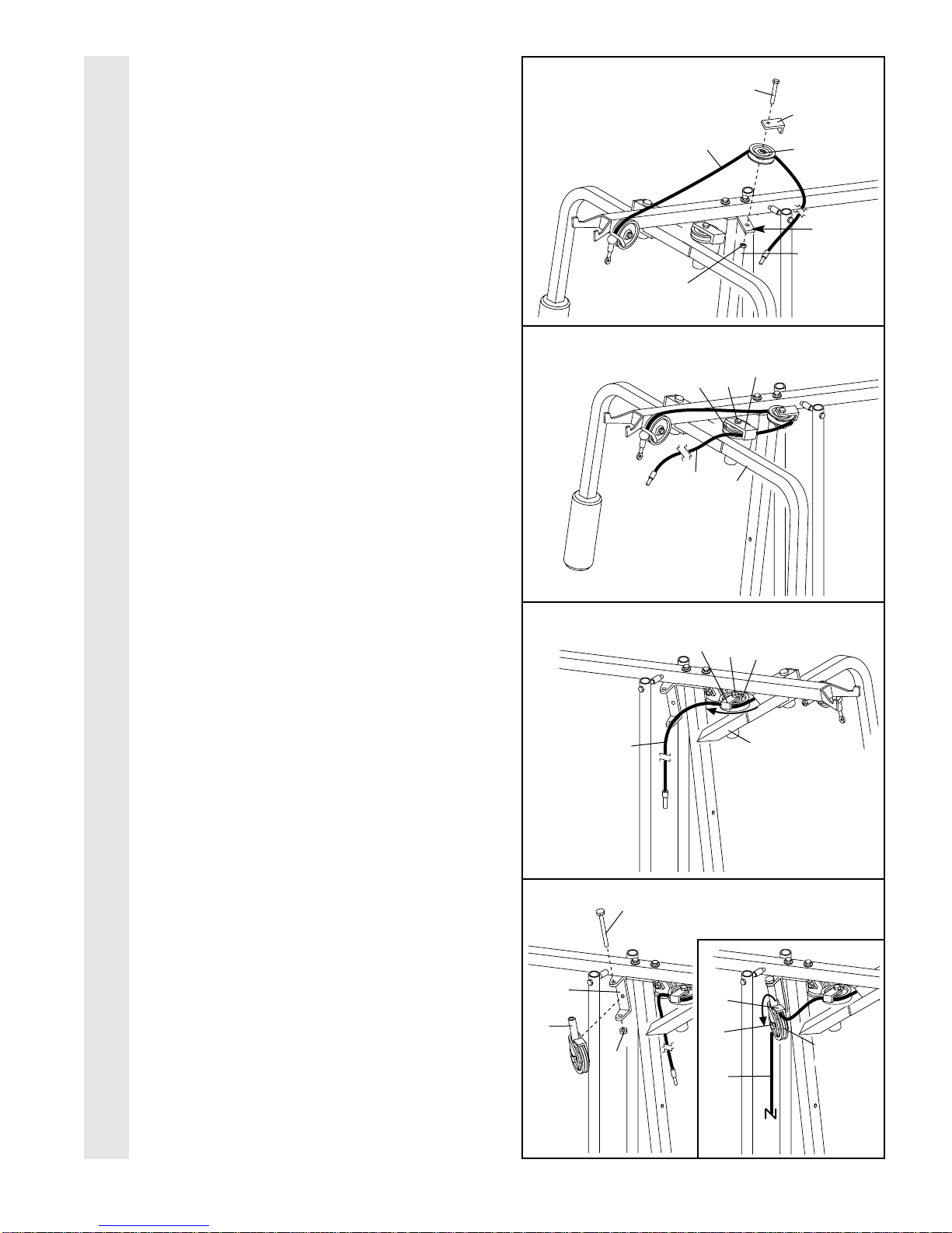
20. Wrap the High Cable (58) around a “V”-Pulley
(50). Attach the Pulley and a Long Cable Trap
(31) to the indicated bracket on the Front
Upright (42) with a 3/8” x 2 1/2” Bolt (86) and
a 3/8” Nylon Locknut (21). Be sure that the
Long Cable Trap is positioned to hold the
Cable in place
21. oute the High Cable (58) around the “V”-
Pulley (50) on the Left Arm (47). Be sure that
the Cable is in the groove of the Pulley
and that the Long Cable Trap (31) is posi-
tioned to hold the Cable in place Tighten
the 3/8” x 2 1/2” Bolt (86) and the 3/8” Nylon
Locknut (not shown).
22. oute the High Cable (58) around the “V”-
Pulley (50) on the ight Arm (48). Be sure
that the Cable is in the groove of the
Pulley and that the Long Cable Trap (31) is
turned to hold the Cable in place Tighten
the 3/8” x 2 1/2” Bolt (86) and the 3/8” Nylon
Locknut (not shown).
23. Attach the Pulley Bracket (20) to the Top
Frame (55) with the 5/16” x 5” Bolt (68) and a
5/16” Nylon Locknut (3). Do not overtighten
the Nylon Locknut; the Pulley Bracket
must be able to move freely
See the inset drawing oute the High Cable
(58) around the 3 1/2” Pulley (15) attached to
the Pulley Bracket (20). Tighten the 3/8” x 2”
Bolt (12) and a 3/8” Nylon Locknut (not
shown). Be sure that the Cable is in the
groove of the Pulley and that the Cable
Trap (66) is turned to hold the Cable in
place
23
20 86
86
31
31
50
50
21
58
58
21
22
CABLE ASSEMBLY
42
47
86
31 50
58
20
68
3
55
48
Bracket
58 15
66
12

13
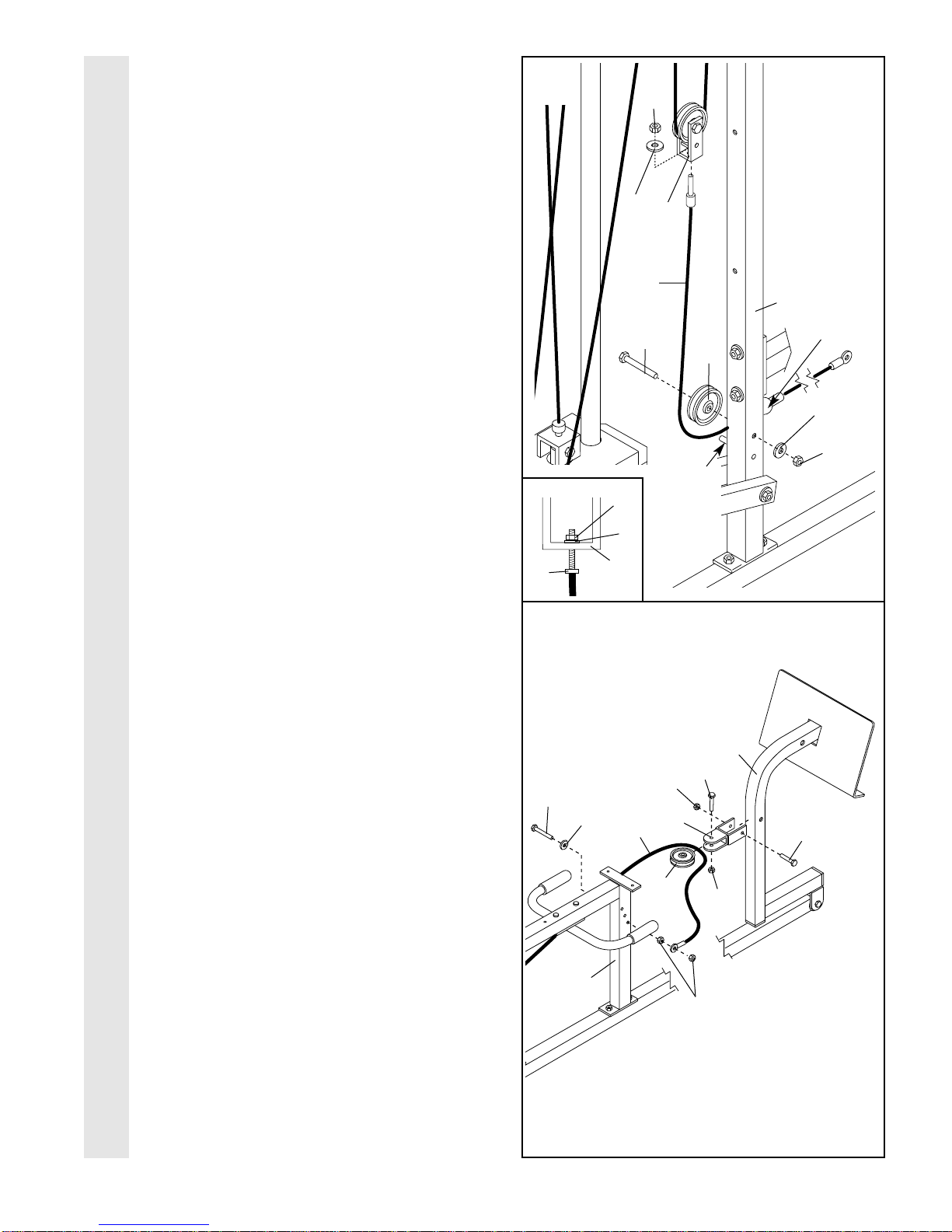
24. See the inset drawing Attach a 3 1/2” Pulley
(15) and a Cable Trap (66) to the upper hole in
a Long “U”-Bracket (57) with a 3/8” x 2” Bolt
(12) and a 3/8” Nylon Locknut (21). Be sure
that the Cable Trap is inside the Long “U”-
Bracket Note: This may come pre-assem-
bled
oute the High Cable (58) through the Long
“U”-Bracket (57) and around the 3 1/2” Pulley
(15) shown in the inset drawing. Be sure that
the Cable is in the groove of the Pulley and
that the Cable and Pulley move smoothly
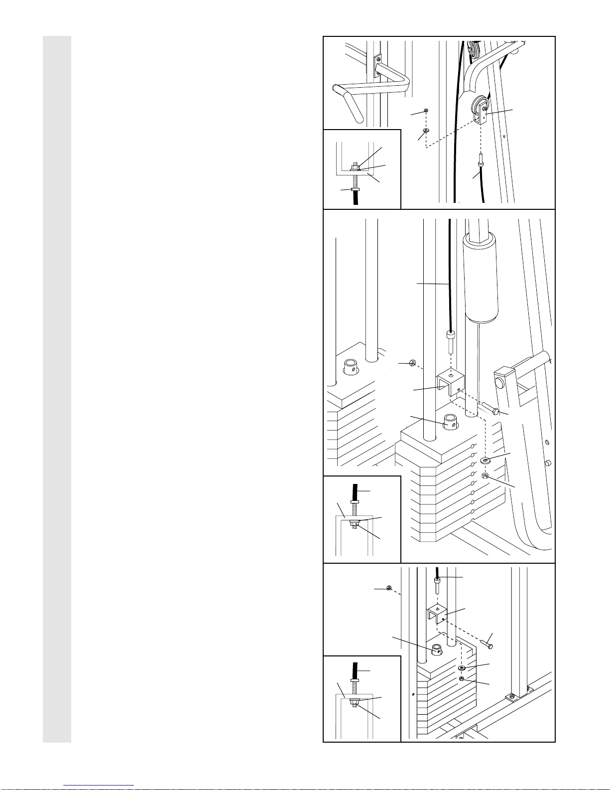
25. Wrap the High Cable (58) around a 3 1/2”
Pulley (15). Attach the Pulley to the bracket on
the Top Frame (55) with a 3/8” x 2” Bolt (12)
and a 3/8” Nylon Locknut (21). Be sure that
the Cable is in the groove of the Pulley and
that the Cable and Pulley move smoothly
26. Note: This assembly step shows how to
complete the assembly of several pre-
attached parts
The 5/8” x 9/16” Spacer (7) has been pre-
attached on the outside of the 3 1/2” Low
Pulley (102) for shipping purposes. emove
the 3/8” Nylon Locknut (21), the Spacer, and
the Pulley from the 3/8” x 3 3/4” Bolt (88). Do
not remove the Bolt The Bolt has been
shown removed for part identification
eattach the 3 1/2” Low Pulley (102), with the
5/8” x 9/16” Spacer (7) between the Pulley and
the Press Frame (17). Do not tighten the 3/8”
Nylon Locknut (21) yet Be sure that the
3/8” x 3 3/4” Bolt (88), the 3/8” Washer (9),
the 5/8” x 9/16” Spacer, the 3 1/2” Low
Pulley, and the 3/8” Nylon Locknut (21) are
oriented as shown
24
58
15
15
66
21
12
57
Bracket
55
21
12
15
58
25
26
CABLE ASSEMBLY
58
57
21
17 102
7
988

14
27. Locate the Low Cable (23) oute the Low
Cable under the 3 1/2” Low Pulley (102). Be
sure that the end of the Cable with the ball
is on the indicated side of the Press Frame
(17) and that the Cable is between the
Pulley and the crossbar on the Press
Frame Tighten the 3/8” Nylon Locknut (21)
and the 3/8” x 3 3/4” Bolt (not shown).
28. oute the Low Cable (23) around the 3 1/2”
Pulley (15) attached to the lower hole in the
Front Upright (42). See the inset drawing
Be sure that the Cable Trap (66) is turned
to hold the Cable in place and that the
Cable is routed around the Pulley as
shown Tighten the 3/8” Nylon Locknut (21)
and the 3/8” x 3 3/4” Bolt (88).
29. oute the Low Cable (23) around the 3 1/2”
Pulley (15) attached to the upper hole in the
Press Frame (17). Be sure that the Cable
Trap (66) is turned to hold the Cable in
place and that the Cable is routed around
the Pulley as shown Tighten the 3/8” Nylon
Locknut (21) and the 3/8” x 3 1/2” Bolt (not
shown).
30. oute the Low Cable (23) around the 3 1/2”
Pulley (15) attached to the upper hole in the
Front Upright (42). See the inset drawing
Be sure that the Cable Trap (66) is turned
to hold the Cable in place and that the
Cable is routed around the Pulley as
shown Tighten the 3/8” Nylon Locknut (21)
and the 3/8” x 3 3/4” Bolt (88).
30
27
23
28
Inset shows view
from other side
29
CABLE ASSEMBLY
21
17
Ball
42
88
23
23
21
15
15
42
66
Inset shows view
from other side
42
88
23 23
15
15 66
42
21
23
17
66
15
102
Crossbar
21
15
31. Attach the end of the Low Cable (23) to the
Long “U”-Bracket (57) with a 1/4” Nylon
Locknut (2) and a 1/4” Washer (10). Do not
completely tighten the Nylon Locknut It
should be threaded onto the end of the
Cable so only a couple of threads are
showing above the Nylon Locknut, as
shown in the inset drawing
32. Attach the High Cable (58) to a Small “U”-
Bracket (71) with a 1/4” Nylon Locknut (2) and
a 1/4” Washer (10). Do not completely tight-
en the Nylon Locknut It should be thread-
ed onto the end of the Cable only a couple
of turns, as shown in the inset drawing
Attach the Small “U”-Bracket (71) to the Short
Weight Tube (108) with a 5/16” x 1 3/4” Bolt
(24) and a 5/16” Nylon Locknut (3).
33. Locate the Military Press Cable (72) Attach
the Military Press Cable to the other Small
“U”-Bracket (71) with a 1/4” Nylon Locknut (2)
and a 1/4” Washer (10). Do not completely
tighten the Nylon Locknut It should be
threaded onto the end of the Cable only a
couple of turns, as shown in the inset
drawing
Attach the Small “U”-Bracket (71) to the Long
Weight Tube (63) with a 5/16” x 1 3/4” Bolt
(24) and a 5/16” Nylon Locknut (3).
33
31
10
58
71
10
32
CABLE ASSEMBLY
57
23
3
24
63
71
10
2
372
2
2
10
57
23
58
10
2
71
72
10
2
71
2
24
108
16
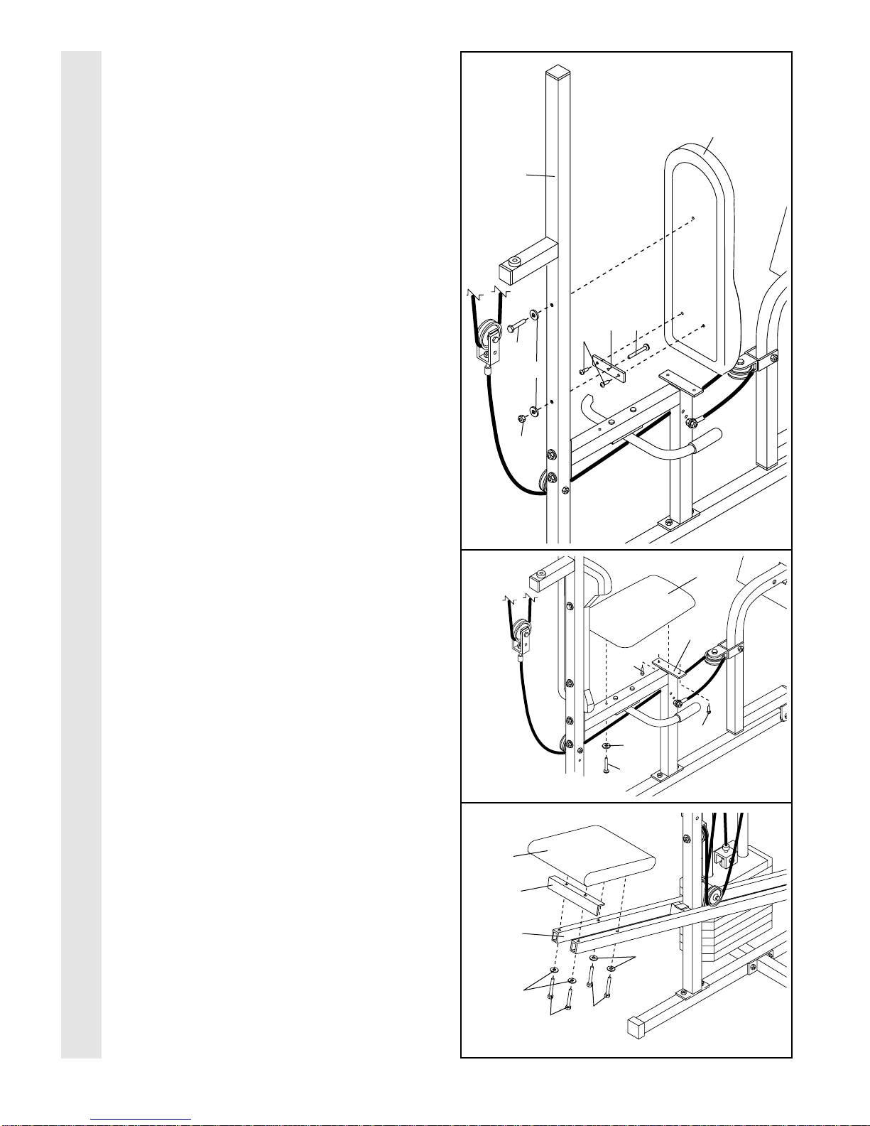
34. Wrap the Military Press Cable (72) around a
“V”-Pulley (50). Attach the Pulley to the Top
Frame (55) with a 3/8” x 2 1/2” Bolt (86) and a
3/8” Nylon Locknut (21).
Wrap the Military Press Cable (72) around a
3 1/2” Pulley (15). Attach the Pulley to the
indicated bracket on the Assist Arm (105) with
a 3/8” x 1 3/4” Bolt (76) and a 3/8” Nylon
Locknut (21). Be sure that the Cable is
between the Pulley and the Assist Arm and
that the Cable and Pulley move smoothly
35. Wrap the Military Press Cable (72) around a
“V”-Pulley (50). Attach the Pulley and a Long
Cable Trap (31) to the Assist Upright (74) with
a 3/8” x 4 1/2” Bolt (112), a 3/8” Washer (9),
and a 3/8” Nylon Locknut (21). Be sure that
the Long Cable Trap is turned to hold the
Cable in place and that the Cable is routed
around the Pulley as shown
Wrap the Military Press Cable (72) around a
3 1/2” Pulley (15). Attach the Pulley to the
other bracket on the Assist Arm (105) with a
3/8” x 1 3/4” Bolt (76) and a 3/8” Nylon
Locknut (21). Be sure that the Cable is
between the Pulley and the Assist Arm and
that the Cable and Pulley move smoothly
34
CABLE ASSEMBLY
Bracket
105
76
50
15
21
21
55
86
72
35
105
921
74
50
31
15
76
72
Bracket
112

17
36. Slide a 5/16” Washer (8) onto a 5/16” x 2 3/4”
Bolt (11). Insert the Bolt through the indicated
hole in the Pivot Arm (101). The Bolt must
be inserted from the side shown Fully tight-
en a 5/16” Nylon Jamnut (93) onto the Bolt.
Wrap the Military Press Cable (72) around a
3 1/2” Pulley (15). Attach the Pulley and a
Cable Trap (66) to the Pivot Arm (101) with
the 3/8” x 3 3/4” Bolt (88), a 3/8” Washer (9),
and a 3/8” Nylon Locknut (21). Be sure that
the Pulley is on the side shown and that
the Cable Trap is positioned to hold the
Cable in place
37. See inset drawing A Attach a 3 1/2” Pulley
(15) and a Cable Trap (66) to the upper hole
in a Long “U”-Bracket (57) with a 3/8” x 2”
Bolt (12) and a 3/8” Nylon Locknut (21). Be
sure that the Cable Trap is inside the Long
“U”-Bracket Note: This may come pre-
assembled
oute the Military Press Cable (72) through
the Long “U”-Bracket (57) and around the
3 1/2” Pulley (15). Be sure that the Cable is
in the groove of the Pulley and that the
Cable and Pulley move smoothly
See inset drawing B Slide the end of the
Military Press Cable (72) onto the end of the
indicated 5/16” x 2 3/4 Bolt (11). Thread
another 5/16” Nylon Jamnut (93) onto the
Bolt. Do not fully tighten the second
Jamnut There must be room between the
two Jamnuts for the end of the Cable to
pivot
37
CABLE ASSEMBLY
72
15
21
57
A
B
12
15
66
57
93
72
36
88
11
72
21
66
101
15
9
93
8
11
18
38. Locate the Leg Press Cable (99) Attach the
end of the Leg Press Cable to the Long “U”-
Bracket (57) with a 1/4” Nylon Locknut (2) and
a 1/4” Washer (10). Do not completely tight-
en the Nylon Locknut It should be thread-
ed onto the end of the Cable only a couple
of turns, as shown in the inset drawing
Wrap the Leg Press Cable (99) around a
3 1/2” Pulley (15). Attach the Pulley to the Leg
Press Upright (56) with the 3/8” x 3 3/4” Bolt
(88), a 3/8” Washer (9), and a 3/8” Nylon
Locknut (21). The ball on the Cable must be
on the indicated side of the Pulley Be sure
that the Cable and Pulley move smoothly
and that the Cable is between the Pulley
and the welded rod
39. Attach the Press Bracket (94) to the Leg
Press Arm (96) with a 5/16” x 3” Bolt (111)
and a 5/16” Nylon Locknut (3).
Wrap the Leg Press Cable (99) around a 3 1/2”
Pulley (15). Attach the Pulley to the Press
Bracket (94) with the 3/8” x 2” Bolt (12) and a
3/8” Nylon Locknut (21).
Slide a 5/16” Washer (8) onto a 5/16” x 2 3/4”
Bolt (11). Insert the Bolt through the lowest
hole in the ear Seat Frame (100) from the
indicated side. Note: The three holes are for
cable adjustment Tighten a 5/16” Nylon
Jamnut (93) onto the Bolt. Slide the end of
the Leg Press Cable (99) onto the end of the
Bolt. Thread another 5/16” Nylon Jamnut onto
the Bolt. Do not fully tighten the second
Jamnut There must be room between the
two Jamnuts for the end of the Cable to
pivot
39
CABLE ASSEMBLY
11
111
96
94
12
21
100 93
8
3
99
15
38
56
57
Ball
9
21
15
2
88
2
10
57
99
99
Welded
od
10
19
40. Locate and open the parts bag labeled
“SEAT ASSEMBLY”
Insert a 1/4” x 2 1/2” Carriage Bolt (92)
through the center hole in a Seat Plate (37).
Attach the Seat Plate to the ear Backrest
(85) with two 1/4” x 3/4” Screws (18).
Insert the 1/4” x 2 1/2” Carriage Bolt (92)
through the indicated hole in the Leg Press
Upright (56). Tighten a 1/4” Nylon Locknut (2)
with a 1/4” Washer (10) onto the Carriage
Bolt. Attach the top of the ear Backrest (85)
to the Leg Press Upright with a 1/4” x 2 1/2”
Screw (43) and another 1/4” Washer.
41. Attach one end of a Seat (13) to the ear
Seat Frame (100) with two 1/4” x 3/4” Screws
(18). Attach the other end of the Seat to the
ear Seat Frame with a 1/4” Washer (10) and
a 1/4” x 2 1/2” Screw (43).
42. Attach the Assist Seat (104) and the Angle
Bracket (110) to the Assist Arm (105) with four
1/4” Washers (10), two 1/4” x 2 3/4” Screws
(114), and two 1/4” x 2 1/2” Screws (43).
SEAT ASSEMBLY
42
40
41
85
2
10
18 92
56
37
43
18
18
13
10
43
10
10
43
114
104
105
100
110

20
43. Attach the Front Backrest (41) to the Front
Upright (42) with two 1/4” x 2 1/2” Screws (43)
and two 1/4” Washers (10). The Backrest
must be oriented as shown.
44. Press a 1 1/2” Square Inner Cap (32) into the
Front Seat Frame (36).
Insert a 1/4” x 2” Carriage Bolt (38) through
the center hole in the Seat Plate (37). Attach
the Seat Plate to the Seat (13) with two 1/4” x
3/4” Screws (18).
Insert the 1/4” x 2” Carriage Bolt (38) through
the indicated hole in the Front Seat Frame
(36). Tighten a 1/4” Nylon Locknut (2) with a
1/4” Washer (10) onto the Carriage Bolt.
Attach the other end of the Seat (13) to the
Front Seat Frame (36) with a 1/4” Washer
(10) and a 1/4” x 2” Machine Screw (81).
45. Press a 1 1/2” Square Inner Cap (32) into the
Leg Lever (29).
Lubricate the 5/16” x 2 1/4” Bolt (33). Attach the
Leg Lever (29) to the Front Seat Frame (36)
with the Bolt and a 5/16” Nylon Locknut (3).
Insert the 3/8” x 2” Eyebolt (35) into the Leg
Lever (29) from the direction shown. Tighten a
3/8” Nylon Locknut (21) with a 3/8” Washer (9)
onto the Eyebolt.
46. est the Front Seat Frame (36) on the indicat-
ed pin in the Front Upright (42). Attach the
Front Seat Frame to the Front Upright with a
5/16” x 2 3/4” Carriage Bolt (14) and the Seat
Knob (40).
SEAT ASSEMBLY
46
43
41
Thick
End
42
44
45
10
13
38
32
36
10
81
37
2
3
921
29
Lubricate
33
35
32
18
43
36
36
42 40
14
Pin
Other manuals for WESY49201
1
This manual suits for next models
1
Other Club Weider Home Gym manuals


Popular Home Gym manuals by other brands


Simply Brands
Simply Brands SBA-00135 instruction manual

ParaBody
ParaBody 435101 Assembly instructions

Powerhouse Fitness
Powerhouse Fitness SESS7132 Owner's manual installation and operation

Torque Fitness
Torque Fitness MJ-SP Assembly instructions

Hoist Fitness
Hoist Fitness ROC-IT RPL-5501-A owner's manual

Weider
Weider WESY78732 user manual