CMOSTEK CMT2250A Instruction Manual

AN118
Rev 1.1 | Page 1 / 31
www.cmostek.com
Introduction
The purpose of this document is to provide the guidelines for the users to configure the CMT2250A on the RFPDK. The part
number covered by this document is shown in the table below.
Table 1. Part Number Covered in this Document
Part Number Description
CMT2250A
True single-chip, ultra low power and high performance device that consists of an OOK RF receiver, a
data decoder and 4 data output pins for various 300 to 480 MHz wireless applications. The decoder
supports 1920, 1527 and 2262 packet formats. The chip is part of the CMOSTEK NextGenRFTM family,
which includes a complete line of transmitters, receivers and transceivers.
The RFPDK (Radio Frequency Products Development Kit) is a PC application developed by CMOSTEK for the NextGenRFTM
product line. Differing from traditional RF chip configuration methods, which usually require complex software programming and
register-based controlling, the RFPKD revolutionarily simplifies the NextGenRFTM product configurations. The user can easily
complete the product configuration by just clicking and inputting a few parameters. After that, the product can be directly used in
the RF system without performing any further configurations.
To help the user to develop their application with CMT2150A and CMT2250(1)A easily, CMOSTEK provides
CMT2150A/2250(1)A One-Way RF Link Development Kits that enables the user to quickly evaluate the performance,
demonstrate the features and develop the application. The Development Kits includes:
RFPDK
USB Programmer
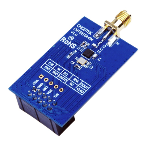
CMT2150A-EM (Tx module)
CMT2250A-EM (Rx on-off control module)
CMT2251A-EM (Rx PWM control module)
AN118
CMT2250A Configuration Guideline
Copyright © By CMOSTEK

AN118
Rev 1.1 | Page 2 / 31
www.cmostek.com
Table of Contents
Introduction....................................................................................................................................................................... 1
1. Getting Started............................................................................................................................................................. 4
2. RF Settings................................................................................................................................................................... 6
2.1 Frequency.............................................................................................................................................................6
2.2 Demodulation........................................................................................................................................................6
2.3 Symbol Rate..........................................................................................................................................................6
2.4 Xtal Tolerance.......................................................................................................................................................6
2.5 Xtal Stabilizing Time..............................................................................................................................................7
3. Operation Settings ...................................................................................................................................................... 8
3.1 Duty-Cycle Mode...................................................................................................................................................8
3.1.1 Always Receive Mode................................................................................................................................9
3.1.2 Duty-Cycle Receive Mode .........................................................................................................................9
3.2 Sleep Time, Rx Time.............................................................................................................................................9
3.2.1 Easy Configuration...................................................................................................................................10
3.2.2 Precise Configuration...............................................................................................................................10
3.3 Wake-On Radio................................................................................................................................................... 11
3.3.1 Application Example 1: Fixed Duty..........................................................................................................12
3.3.2 Application Example 2: Wake on Preamble.............................................................................................12
3.4 Rx Early Exit........................................................................................................................................................ 14
3.4.1 Application Example 1: Fixed Duty with Rx Early Exit..............................................................................14
3.4.2 Application Example 2: Wake on Preamble with Rx Early Exit ................................................................15
4. OOK Settings............................................................................................................................................................. 16
4.1 Demod Method.................................................................................................................................................... 16
4.1.1 Fixed Threshold Method..........................................................................................................................16
4.1.2 Peak Threshold Method...........................................................................................................................17
4.2 Fixed Demod TH................................................................................................................................................. 17
4.3 Peak Drop Step, Peak Drop Rate....................................................................................................................... 17
5. Decode Settings ........................................................................................................................................................ 19
5.1 Decoder .............................................................................................................................................................. 19
5.1.1 1920 Normal Packet Structure.................................................................................................................20
5.1.2 1920 Study Packet Structure...................................................................................................................21
5.1.3 1920 Bit Format.......................................................................................................................................21
5.1.4 1527 Normal Packet Structure.................................................................................................................22
5.1.5 1527 Study Packet Structure...................................................................................................................23
5.1.6 1527 Bit Format.......................................................................................................................................23
5.1.7 2262 Packet Structure .............................................................................................................................24
5.1.82262 Bit Format.......................................................................................................................................25
5.2 Pulse Mode, Pulse Time..................................................................................................................................... 25
5.3 Bit Format............................................................................................................................................................ 26
5.4 Valid Reception................................................................................................................................................... 26
5.5 Data Pin Reset Code .......................................................................................................................................... 27
6. Study Settings ........................................................................................................................................................... 28
6.1 ID Study.............................................................................................................................................................. 28

AN118
Rev 1.1 | Page 3 / 31
www.cmostek.com
6.2 Factory Code....................................................................................................................................................... 28
6.3 Study RSSI TH.................................................................................................................................................... 29
6.4 Study Time Window............................................................................................................................................ 29
7. Document Change List.............................................................................................................................................. 30
8. Contact Information .................................................................................................................................................. 31

AN118
Rev 1.1 | Page 4 / 31
www.cmostek.com
1. Getting Started
Install RFPDK on the computer. The detail of the installation can be found in Chapter 7 of “AN113 CMT2150A/2250(1)AOne-Way
RF Link Development Kits User’s Guide”.
Setup the development kits as shown in Figure 1 before configuring the CMT2250A. The Application with CMT2250A can be
CMT2250A-EM V1.0 provided by CMOSTEK, or the PCB designed by the user with CMT2250A.
Figure 1. CMT2250A Configuration Setup
Start the RFPDK from the computer’s desktop and select CMT2250A in the Device Selection Panel shown in Figure 2. Once a
device is selected, the Device Control Panel appears as shown in Figure 3. Because the Advanced Mode covers all the
configurable features / parameters while the Basic Mode only contains a subset, the Advanced Mode is described in this
document.
Figure 2. Device Selection Panel

AN118
Rev 1.1 | Page 5 / 31
www.cmostek.com
Figure 3. Advanced Mode of Device Control Panel

AN118
Rev 1.1 | Page 6 / 31
www.cmostek.com
2. RF Settings
Figure 4. RF Settings
Table 2. RF Settings Parameters
Parameters Descriptions Default Mode
Frequency The receive radio frequency, the range is from 300 to 480 MHz,
with resolution of 0.01 MHz. 433.92 MHz Basic
Advanced
Demodulation The demodulation type, only OOK demodulation is supported in
this product. OOK Basic
Advanced
Symbol Rate The receiver symbol rate, the range is from 0.1 to 40.0 ksps,
with resolution of 0.1 ksps. 4.8 ksps Basic
Advanced
Xtal Tolerance The sum of the crystal frequency tolerance of the Tx and the
Rx, the range is from 0 to ±200 ppm.
±20 ppm Basic
Advanced
Xtal Stabilizing Time Time for the device to wait for the crystal to get settled after
power up. The options are: 78, 155, 310, 620, 1240 or 2480 us. 310 us Basic
Advanced
2.1 Frequency
CMT2250A covers a wide range of the receive radio frequency from 300 to 480 MHz. The frequency is accurate to two decimal
places on the RFPDK.
2.2 Demodulation
CMT2250A only supports OOK demodulation.
2.3 Symbol Rate
With OOK demodulation, CMT2250A supports 0.1 – 40.0 ksps symbol rate. The symbol rate tolerance of the device is from –25%
to +25% of the “Symbol Rate” configured on the RFPDK. For example, if the user set the symbol rate to 9.6 ksps on the RFPDK,
the covered symbol rate of the transmitted data is from 7.2 to 12 ksps. If the user set it to 40 ksps, the covered range is from 30 to
40 ksps. Any symbol rate outside the range of 0.1 – 40 ksps is not supported.
2.4 Xtal Tolerance
This is the sum of the crystal frequency tolerance of the transmitter and receiver. The input range is from 0 to ±200 ppm. The
wide range of crystal tolerance allows very low cost crystal to be used in the applications.
Assuming the crystal tolerance of the transmitter is ±10 ppm, and the crystal tolerance of the receiver is ±20 ppm, the user shall
enter the total tolerance of ±30 ppm on the RFPDK. The RFPDK takes this into account to calculate the receiving bandwidth.
When the crystal tolerance increases, the bandwidth is increased and the sensitivity is reduced.
It is also recommended for the user to perform on-field testing of the sensitivity with the desired setting of the Xtal Tolerance.

AN118
Rev 1.1 | Page 7 / 31
www.cmostek.com
2.5 Xtal Stabilizing Time
This defines the time for the device to wait for the crystal to get stable after it is powered up. The user shall select one of the six
options provided on the RFPDK that is most suitable for the crystal used in the applications.

AN118
Rev 1.1 | Page 8 / 31
www.cmostek.com
3. Operation Settings
Figure 5. Operation Settings
Table 3. Operation Settings Parameters
Parameters Descriptions Default Mode
Duty-Cycle Mode Turn on/off the duty-cycle mode, the options are: on or
off. On Basic
Advanced
Sleep Time The sleep time in duty-cycle mode, the range is from 3 to
134,152,192 ms. 3 ms Basic
Advanced
Rx Time The receive time in duty-cycle mode, the range is from
0.04 to 2,683,043.00 ms. The default value is different
when the Wake-On Radio (WOR) is turned on or off.
10,000.00 ms
(WOR is off) or
20.00 ms
(WOR is on)
Basic
Advanced
Rx Time Ext The extended receive time in duty-cycle mode, the range
is from 0.04 to 2,683,043.00 ms. It is only available when
the Wake-On Radio is turned on. 200.00 ms Advanced
Rx Early Exit Turn on/off the Rx early exit function, the options are: on
or off. Off Advanced
Wake-On Radio Turn on/off the wake-on radio function, the options are:
on or off. It is only available when the Duty-Cycle Mode is
turned on. Off Advanced
3.1 Duty-Cycle Mode
This allows the user to determine how the radio is controlled, as shown in the figure below.
PUP
SLEEP
XTAL TUNE
RX
Duty-Cycle Receive Mode
(“Duty-Cycle Mode”is set to On )
PUP
Always Receive Mode
(“Duty-Cycle Mode”is set to Off )
SLEEP
TUNE RX
Figure 6. Radio Operation with Duty-Cycle Mode On and Off

AN118
Rev 1.1 | Page 9 / 31
www.cmostek.com
3.1.1 Always Receive Mode
If the Duty-Cycle Mode is turned off, the device will go through the Power Up (PUP) sequence, stay in the SLEEP state for about
3 ms, tune the receive frequency, and finally stay in the RX state until the device is powered down. The power up sequence,
which takes about 4 ms to finish, includes the task of turning on the crystal and calibrating the internal blocks. The device will
continuously receive the incoming RF signals during the RX state and perform the decoding to control the data pins. The figure
below shows the timing characteristics and current consumption of the device from PUP to RX.
SLEEP
60 nA
Time =
about 3 ms
TUNE RX
Current
3.8 mA
Time =
about 300 us
2.0 mA
State
900 uA
Time =
about 4 ms
PUP
Figure 7. Timing and Current Consumption for Always Receive Mode
3.1.2 Duty-Cycle Receive Mode
If the Duty-Cycle Mode is turned on, after the PUP the device will automatically repeat the sequence of SLEEP, XTAL, TUNE and
RX until the device is powered down. This allows the device to re-tune the synthesizer regularly to adept to the changeable
environment and therefore remain its highest performance. The device will continuously receive any incoming signals during the
RX state and perform the decoding to control the data pins. The PUP sequence consumes about 9.5 ms which is longer than the
4 ms in the Always Receive Mode. This is because the LPOSC, which drives the sleep timer, must be calibrated during the PUP.
SLEEP TUNE RX
Current
3.8 mA
XTAL SLEEP TUNE RX
XTAL
440 nA 520 uA
2.0 mA
3.8 mA
440 nA 520 uA
2.0 mA
900 uA
Time =
about 9.5 ms Time =
Sleep Time
Time =
Xtal Stabilizing Time
Time =
about 300 us
Time =
Rx Time
PUP
State
Figure 8. Timing and Current Consumption for Duty-Cycle Receive Mode
It is strongly recommended for the user to turn on the Duty-Cycle Mode option. The advantages are:
Maintaining the highest performance of the device by regular frequency re-tune.
Increasing the system stability by regular sleep (resetting most of the blocks).
Saving power consumptions of both of the Tx and Rx device.
As long as the Sleep Time and Rx Time are properly configured, the transmitted data can always be captured by the device.
3.2 Sleep Time, Rx Time
When the Duty-Cycle Mode is turned on, the Sleep Time and Rx Time is opened to the user to configure. Proper setting of these

AN118
Rev 1.1 | Page 10 / 31
www.cmostek.com
two values is important for the device to work in an expected scenario.
3.2.1 Easy Configuration
When the user wants to take the advantage of maintaining the highest system stability and performance, and the power
consumption is not the first concern in the system, the Easy Configuration can be used to let the device to work in the duty-cycle
mode without complex calculations, the following is a good example:
RX
T = Rx Time (1000 ms)
RX State
TX Data
SLEEP, XTAL and TUNE
T = Sleep Time (3 ms) +
XTAL Stabilizing Time (310 us) +
Tuning Time (300 us) = 3.61 ms
T = Packet Length (72 ms) A missed packet Two missed packets
Demodulated
Data
output data corrupted output data corrupted
time
Figure 9. Tx and Rx relationship of Easy Configuration
In this example, the Tx device transmits the data at 1.2 ksps and there are 60 symbols in one data packet. Thus, the packet
length is 72 ms. The user can do the following:
Set the Sleep Time to the minimum value of 3 ms.
Set the Rx Time to 1 second which is much longer than the packet length.
Let the Tx device to send out 3 continuous data packets in each transmission.
Because the Sleep Time is very short, the non-receive time is only about 3.61 ms (the sum of the Sleep Time, XTAL stabilizing
time and the tuning time), which is much shorter than the packet length of 72 ms. Therefore, this non-receive time period will only
have a chance to corrupt no more than 2 packets receiving. During the non-receive time period, the demodulated data will be 0.
Because the Rx Time is very long, and 3 continuous data packets are sent in each transmission, there is at least 1 packet that
can be completely received by the device and get demodulated with no corruption. The packet can be decoded successfully.
3.2.2 Precise Configuration
If the system power consumption is a sensitive and important factor in the application, the Precise Configuration can be used.
The paragraphs below describe the principle of the precise configuration. Please also use the spreadsheet “Duty Cycle
Calculator.xlsx” to assist the calculation. The calculator can be obtained on the RFPDK or downloaded from CMOSTEK official
website.

AN118
Rev 1.1 | Page 11 / 31
www.cmostek.com
One Packet
IDLE
IDLE
IDLE
Length of Packet x 2 +
Packet Interval < Rx Time Tx Burst Time > Rx Cycle
Tx starts transmittion
Tx Sending Data :
Missed
Received
Rx Receiving Data :
RX Sleep
Rx Cycle < Tx Burst Time
SLEEP
Receiving Sleeping Xtal stabilizing
and Frequency Tuning
Rx Cycle = Sleep Time + Xtal Stabilizing Time +
Tune Time + Rx Time x 2
time
IDLE
SLEEP SLEEP SLEEP
Tx starts transmittion
Received
time
XTAL,
TUNE
RX
Figure 10. Tx and Rx Relationship of Precise Configuration
The above figure is a conceptual diagram to explain the timing relationships between the Tx and the Rx device. The user will
have to make some trade-off amount the packet length, packet interval, Tx burst time, Rx receive time and Rx sleep time, to
optimize the power consumption of the Rx device. Two requirements must be fulfilled:
Length of Packet x 2 + Packet Interval < Rx Time
Tx Burst Time > Rx Cycle, where Rx Cycle = Xtal Stabilizing Time + Tune Time + Rx Time x 2 + Sleep Time
The Rx Time must always be longer than the packet length times two plus the packet interval which is determined by the Tx
setting (symbol rate, number of symbol per packet, etc). This ensures that the receiver always has a chance to capture at least 1
packet within a Tx Burst. Normally, it is recommended for the user to set the Rx Time to be longer than 2 or more packets plus the
intervals, especially when the application environment is noisy and interferential. The user must also ensure that the Rx Cycle is
shorter than the Tx Burst Time. In another words, it must be ensured that at least 1 RX state happens during 1 Tx Burst.
3.3 Wake-On Radio
The wake-on radio function is only supported for 1920 packet format. It is an effective power consumption saving technique that
minimizes the receive time while it guarantees that the device can successfully capture the transmitted data. The following
application examples are provided for better understanding. Please also use the spreadsheet “Duty Cycle Calculator.xlsx” to
assist the calculation.
Please note that the sleep timer which is driven by the LPOSC has ±1% frequency tolerance. The receive timer is driven by the
crystal oscillator therefore the timer accuracy is crystal-dependent.

AN118
Rev 1.1 | Page 12 / 31
www.cmostek.com
3.3.1 Application Example 1: Fixed Duty
Table 4. Fixed Duty Configurations
Options Value
Sleep Time 5,000 ms
Rx Time 400 ms
Rx Time Ext NA
Wake-On Radio Off
Preamble NA
Rx Early Exit Off
Valid Reception 1 packet
The sleep and receive time is fixed to 5,000 ms and 400 ms, respectively.
The Xtal Stabilizing Time is set to 310 us.
SLEEP SLEEP
RX
(400 ms)
XTAL
(310 us) SLEEP
(5,000 ms)
TUNE
(300 us) XTAL
(310 us) TUNE
(300 us) RX
(400 ms)
time
Figure 11. Fixed Duty Operation
After a successful power up, the device enters the SLEEP state. When it reaches the sleep timeout of 5,000 ms, it switches to
XTAL state to wait for the crystal to get stable. Subsequently it takes about 300 us to tune the frequency synthesizer to the
desired frequency. Once the frequency synthesizer is locked, the device starts receiving. When the Rx timer is timeout at 400 ms,
the device switches back to the SLEEP state and repeat the same cycle continuously until it is powered down.
In this example, the non-receive time is 5,000 + 0.31 + 0.3 = 5,000.61 ms. The receive time is 400 ms. Therefore, according to
the principle introduced in the “Precise Configuration”, the Tx burst time must be longer than 5,400.61 ms, and 2 data packets
must appear during the RX state for safety.
3.3.2 Application Example 2: Wake on Preamble
Table 5. Wake on Preamble Configurations
Options Value
Sleep Time 800 ms
Rx Time 20 ms
Rx Time Ext 200 ms
Wake-On Radio On
Preamble 16-symbol
Rx Early Exit Off
Valid Reception 1 packet
The wake-on radio function provides a powerful scheme to save the power. In this example, the receive time is set to 20 ms
which is much shorter than the packet length. The sleep time is 800 ms.
When there is no effective signal received, the radio acts like the one introduced in the Application Example 1. Because the Rx
time is much shorter, more power is saved.

AN118
Rev 1.1 | Page 13 / 31
www.cmostek.com
SLEEPSLEEP RX
(20 ms)
XTAL
(310 us) SLEEP
(800 ms)
TUNE
(300 us) RX
(20 ms)
XTAL
(310 us) TUNE
(300 us)
time
Figure 12. Preamble Wake-On Operation without Preamble Detected
If a valid preamble is received, the RX state is extended to RX EXT state which is long enough for more than 2 data packets
reception. A valid preamble means the preamble of the size (16-symbol in this example) defined on the RFPDK. Please note that
the preamble defined for the Rx device is not necessarily the entire preamble length that is transmitted by the Tx device.
SLEEP SLEEP
(800 ms)
RX
(20 ms)
Wake on preamble
Data Packet
RX EXT
(200 ms)
XTAL
(310 us) TUNE
(300 us)
Data Packet
time
Preamble
Figure 13. Preamble Wake-On Operation with Preamble Detected
In order to ensure that the preamble can be captured by the Rx, the RX EXT must be longer than the valid preamble which is
16-symbol.
SLEEP, XTAL, TUNE RX EXTRX
Preamble
time
SLEEP, XTAL, TUNE RX
Data Packet Data Packet
Figure 14. The Transmitted Preamble Length
Also, as shown in the above figure, for the Tx device, the transmitted preamble length must be long enough to ensure the Rx
reception:
Preamble Length > RX + SLEEP + XTAL + TUNE + RX
The longer the transmitted preamble length is, the more power the Tx device consumes in each transmission. Therefore, this
example is suitable for the application where the Tx device does not send out data very often, and the Rx device is very sensitive
about the current consumption.
In most of the applications, it is recommended that the CMT2250A can be paired with the CMT2150A (Low-Cost 240 – 480 MHz
OOK Stand-Alone Transmitter with Encoder). However, since the maximum size of the preamble sent by CMT2150A is only
16-symbol, the size might not be long enough to fulfill the WOR timing requirement introduced above. In this case, it is suggested
to use the stand-alone transmitter CMT2110A (Low-Cost 240 – 480 MHz OOK Transmitter) with an external MCU to pair with the

AN118
Rev 1.1 | Page 14 / 31
www.cmostek.com
CMT2250A. The external MCU can produce the data packet with any length of preamble that is required.
3.4 Rx Early Exit
Rx Early Exit function allows the device to exit the RX state as soon as a certain number of packets defined by “Valid Reception”
have been successfully received and decoded. This function is only available in duty-cycle receive mode. It is designed to further
save the power consumption by shortening the receive time. The below are a few application examples.
3.4.1 Application Example 1: Fixed Duty with Rx Early Exit
Table 6. Fixed Duty with “Rx Early Exit = On” Configurations
Options Value
Sleep Time 5,000 ms
Rx Time 400 ms
Rx Time Ext NA
Wake-On Radio Off
Preamble NA
Rx Early Exit On
Valid Reception 1 packet
This example is based on the one descript in Chapter 3.3.1. When no signal is being transmitted, the device works in the fixed
duty mode. The Rx Time is 400 ms.
SLEEP SLEEP
RX
(400 ms)
XTAL
(310 us) SLEEP
(5,000 ms)
TUNE
(300 us) XTAL
(310 us) TUNE
(300 us) RX
(400 ms)
time
Figure 15. Fixed Duty Operation
Because the Rx Early Exit function is turned on and the “Valid Reception” is set to 1 packet, the device automatically exits the RX
state as soon as 1 valid packet is successfully captured. As shown in the below figure, due to the happening of the early exit
event, the device only stays in the RX state for 160 ms in the current cycle, saving 240 ms from the original 400 ms.
SLEEP SLEEP
(5000 ms)
Early Exit
Data Packet
RX
(160 ms, saving 240 ms)
XTAL
(310 us) TUNE
(300 us)
time
Data Packet
Figure 16. Fixed Duty with Rx Early Exit Operation

AN118
Rev 1.1 | Page 15 / 31
www.cmostek.com
3.4.2 Application Example 2: Wake on Preamble with Rx Early Exit
Table 7. Wake on Preamble with “Rx Early Exit = On” Configurations
Options Value
Sleep Time 800 ms
Rx Time 20 ms
Rx Time Ext 200 ms
Wake-On Radio On
Preamble 16-symbol
Rx Early Exit On
Valid Reception 2 packets
This example is based on the one descript in Chapter 3.3.2.
Because the Rx Early Exit function is turned on and the “Valid Reception” is set to 2 packets, the device automatically exits the
RX state as soon as 2 identical valid packets are successfully captured. As shown in the below figure, due to the happening of
the early exit event, in the current cycle the Rx Time Ext is shortened from 200 ms to 150 ms.
SLEEP SLEEP
(800 ms)
RX
(20 ms)
Wake on Preamble
RX EXT
(150 ms, saving 50 ms)
XTAL
(310 us) TUNE
(300 us)
time
Early Exit
Data Packet Data PacketPreamble
Figure 17. Preamble Wake-On with Rx Early Exit

AN118
Rev 1.1 | Page 16 / 31
www.cmostek.com
4. OOK Settings
Figure 18. OOK Settings
Table 8. OOK Settings
Parameters Descriptions Default Mode
Demod Method The OOK demodulation methods, the options are: Peak
TH, or Fixed TH. Peak TH Advanced
Fixed Demod TH The threshold value when the Demod Method is “Fixed
TH”, the range is from 0 to 255. It is only available when
Demod Method is set to Fixed TH. 80 Advanced
Peak Drop Turn on/off the RSSI peak drop function, the options are
on, or off. On Advanced
Peak Drop Step The RSSI peak drop step size, the options are: 1, 2, 3, 5, 6,
9, 12 or 15. 2 Advanced
Peak Drop Rate The RSSI peak drop rate, the options are: 1 step/4
symbols, 1 step/2 symbols, 1 step/1 symbols, or 1 step/0.5
symbols. 1 step/4 symbols Advanced
4.1 Demod Method
The OOK demodulation is done by comparing the RSSI to a demodulation threshold. The threshold is an 8-bit binary value that is
comparable to the 8-bit digitized RSSI.
4.1.1 Fixed Threshold Method
When the “Demod Method” is set to Fixed TH, once the RSSI goes above the threshold, logic 1 is output as the demodulated
signal, otherwise logic 0 is output. The demodulated signal is then sent to the decoder to perform packet decoding and data pins
controlling.
0
255 User-defined
Fixed Demod TH
Demodulated
Data
Time
RSSI
Figure 19. OOK Demodulation Using Fixed Threshold

AN118
Rev 1.1 | Page 17 / 31
www.cmostek.com
4.1.2 Peak Threshold Method
When the “Demod Method” is set to “Peak TH”, the demodulator dynamically detects the peak value of the RSSI. The
comparison threshold (Demod TH) is then obtained by reducing N dB from the peak. The magnitude of N is internally calculated
according to the different bandwidths, symbol rates and filtering settings.
0
255 Detected Signal Peak
Time
RSSI
Demodulated
Data
Reduced by N dB
Demod TH
Figure 20. OOK Demodulation Using Peak-N Threshold
When the signal disappears, the peak is detected on the noise floor (see more descriptions in the next section).
To compare the two different modes, the Peak TH mode is used by default on the RFPDK, due to its high adaptability to the
different environments and it is carefree for the user. The Fixed TH mode allows the system to only receive the signals whose
strength is above a preset value, which is helpful for the user to control the communication distance between the Tx and the Rx.
4.2 Fixed Demod TH
This parameter defines the value of the fixed threshold. It is only available when the Demod Method is set to Fixed TH.
4.3 Peak Drop Step, Peak Drop Rate
When using the Peak TH mode, the Peak Drop function is very useful to deal with the long string of logical “0” on the received
data.
When the Peak Drop function is turned off, the dynamically detected peak remains 8 symbols. This means within a moving
8-symbol time window the peak value of the RSSI will be recorded to calculate the demodulation threshold. This might have
problem when a string longer than 8 symbols of logical “0” appears, as shown in the below figure.
0
255
Time
RSSI
Demodulated
Data
Reduced by N dB
8 Symbols 24 Symbols
Signal Peak
Demod TH
Peak
Suddenly Drops Peak
Suddenly Rises
Figure 21. OOK Demodulation Using Peak-N Threshold, with Peak Drop Off

AN118
Rev 1.1 | Page 18 / 31
www.cmostek.com
As shown in the above figure, the transmitter sends out a “1” symbol followed by thirty-one “0” symbols. After the signal peak
stands for 8 symbols, it suddenly drops to just above the floor noise. From that point the detected peak is actually the floor noise
peak and the demodulated data is unpredictable. The last 24 symbols of “0” are then lost or partially lost. Practically, the similar
situation does exist and this will lead to failure of demodulation.
The problem can be resolved by turning on the Peak Drop function. It allows the detected peak to drop slowly in order to
recognize more symbols of “0”. The following figure gives an example. In this example, the Peak Drop Step parameter is set to 12
(RSSI code) on the RFPDK, with the Peak Drop Rate set to 1 step per 2 symbols.
The value of the Peak Drop Step defines how many RSSI codes the signal peak drops each time. The value of Peak Drop Rate
defines how fast the peak drop is performed.
0
255 Signal Peak
Time
RSSI
Demodulated
Data
Reduced by N dB
Demod TH
8 Symbols 24 Symbols
Peak Drop Step
= 12 Peak Drop Rate =
1 step / 2 symbols
Figure 22. OOK Demodulation Using Peak-N Threshold, with Peak Drop On
As shown in the above figure, after remaining 8 symbols, the peak drops step by step until the next ‘1’ symbol comes. The
demodulation threshold drops accordingly to the peak and stays above the noise floor during the long ‘0’ sequence, and therefore
allows the device to produce the correct demodulation result. The longer it takes for the peak to drop to the noise floor, the more
“0” the system can demodulate. In practice, the bottom of the dropping is the noise floor which varies depending on the different
environments. Below is an example to calculate the total drop time:
Assuming the signal peak is 240, to drop from 239 to 0, the total drop time is computed by:
Drop Time =Peak Drop Step Peak Drop Ratex
240 , units in Rx symbols
Since the maximum step size is 15 (in terms of RSSI code) and the highest rate is 1 step per 0.5 symbol, the fastest peak drop
from 239 to 0 is: 240 / (15 * (1/0.5)) = 8-symbol time. Since the minimum step is 1 and the lowest rate is 1 step per 4 symbols, the
slowest peak drop from 239 to 0 is: 240 / (1 * (1/4)) = 960-symbol time.
It should be noticed that, in the above computations the “time” is measured in “numbers of the Rx symbol” according to the
symbol rate configured on the RFPDK. The user should take the symbol rate offset into account during the calculations. For
instance, if the Rx symbol rate is set to 4.8 ksps while the Tx actually transmits the data at 3.6 ksps (with -25% offset), the signal
peak only stands for 6 symbols (at 3.6 ksps) instead of 8 symbols before starting the dropping. Also, the peak drop rate doubles.
CMOSTEK recommends turning on the peak drop function on the RFPDK. By default, the step is set to 2 and the rate is set to 1
step per 4 symbols, and thus it takes 480 symbols to drop from 239 to 0. This default setting fulfills the requirements in most of
the wireless applications using OOK. The user does not have to change them unless particular situation are found, such as, the
transmitted signals are very small, symbol rate offset is too large, or the string of ‘0’ is too long.

AN118
Rev 1.1 | Page 19 / 31
www.cmostek.com
5. Decode Settings
Figure 23. Decode Settings
Table 9. Decode Settings Parameter
Parameter Descriptions Default Mode
Decoder Select the packet decoding format; the options are: 1920,
1527 and 2262. See Table 11, Table 12 and Table 13 for
the configurable parameters in each format. 1527 Basic
Advanced
Pulse Mode Turn on/off the data pins pulse mode; the options are: On
or Off. Off Basic
Advanced
Pulse Time This defines the pulse time; the range is from 1 to 16,383
ms. It is only available when Pulse Mode is enabled. It is
only available when the Pulse Mode is turned on. 10,000 ms Basic
Advanced
Bit Format
This tells the device how many symbols are used to
construct a single bit in the 1920 mode. The options are: 3,
4, 5 or 6 symbols/bit. The Bit Format is fixed at 4
symbols/bit in 1527 mode and 8 symbols/bit in 2262 mode.
3 Advanced
Valid Reception This defines how many identical packets
the device
consecutively received represent a valid reception, the
options are: 1 packet, 2 packets, 3 packets or 4 packets. 2 packets Advanced
Data Pin Reset Code
This defines the 4-bit data code received to reset the 4
data pins. The options are 0 or 1 for each bit. In 2262, the
number of bits of this code is identical to the Data Length
which is automatically calculated according to the Sync ID
Length.
0000 Advanced
5.1 Decoder
The device supports 3 types of decoding formats: 1920, 1527 and 2262. The packets of these 3 modes have different structures
as introduced in the below sub-sections. The following is a feature summary:
Table 10. Feature Summary of the 3 Decoding Formats
Format Bit Format Sync ID Length Data Length CRC ID Study Wake-On Radio
1920 3/4/5/6 sym/bit 1 – 32 bits 4 bits Support Support Support
1527 4 sym/bit 20 bits 4 bits NA Support Not Support
2262 8 sym/bit 8 – 11 bits 1 – 4 bits NA Not Support Not Support

AN118
Rev 1.1 | Page 20 / 31
www.cmostek.com
In the below explanation (also on the RFPDK), the packet structural diagrams show all the elements in the packets, as well as the
available options corresponding to each element.
Furthermore, some elements in the packet are measured in the unit of “symbol”, while some of them are measured in the unit of
“bit”. For those which have the unit of “bit”, one “bit” is constructed (encoded) by several “symbols”. In the figures, “SYM”
represents the word “symbol”.
5.1.1 1920 Normal Packet Structure
The normal packet is used to control the data pins. It contains an optional Preamble, a 32-symbol Head_N indicating the current
packet is a Normal packet, a Sync ID, 4-bit Data and an optional 8-symbol CRC.
Figure 24. 1920 Normal Packet Structure
Table 11. Configurable Parameters in 1920 Packet
Parameter Descriptions Default Mode
Preamble The size of the valid preamble, the options are: None,
8-symbol, 16-symbol, 24-symbol or 32-symbol. None Basic
Advanced
Address (Sync ID)
Length The range of the Sync ID Length is from 1 to 32 bits. 32 bits Basic
Advanced
Address (Sync ID)
Value The value of the Sync ID has the range from 0 to 2Length-1. 0 Basic
Advanced
CRC The CRC validation increases the reliability of the
reception. The options are: Enable or Disable. Disable Basic
Advanced
Preamble
The pattern of a 16-symbol preamble is shown below:
1
SYM
1
SYM 1
SYM 1
SYM 1
SYM 1
SYM 1
SYM 1
SYM
1
SYM 1
SYM 1
SYM 1
SYM 1
SYM 1
SYM 1
SYM 1
SYM
Figure 25. 1920 16-symbols Preamble Pattern
Typically, if the WOR (Wake-On Radio) function is turned on, the preamble is used to extend the receive time. Please see
Chapter 3.3.2 for considerations of using the WOR function in the application of “Extended by Preamble”.
Head_N
The user does not need to control the Head_N because it is automatically generated by the CMT2150A and recognized by the
CMT2250A. The pattern of Head_N is shown below.
2
SYM
2
SYM 2
SYM
2
SYM 1
SYM
1
SYM 1
SYM 1
SYM
2
SYM 1
SYM
1
SYM 2
SYM
2
SYM 2
SYM
2
SYM
1
SYM 1
SYM 1
SYM 1
SYM
1
SYM 1
SYM 1
SYM 1
SYM
Figure 26. 1920 Head_N Pattern
Table of contents
Other CMOSTEK Receiver manuals
