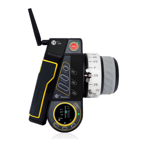
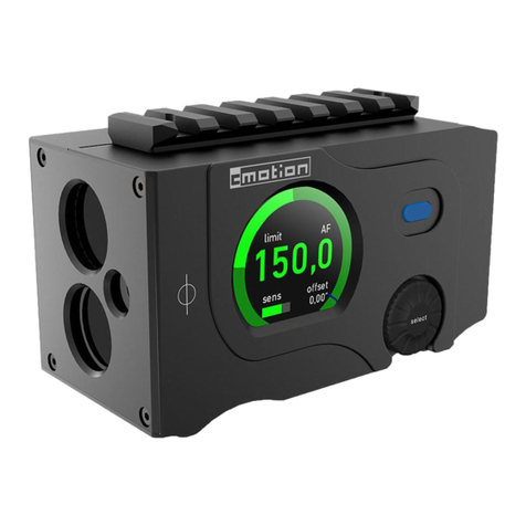
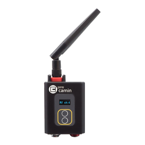
cmotion compactLCS User manual

All content © 2015, cmotion GmbH. All specifications subject to change without notice. http://www.cmotion.eu
V 1.03 | Nov 30th, 2015
Software Release Package: 2015_03
compactLCS
User Guide

All content © 2015, cmotion GmbH. All specifications subject to change without notice. http://www.cmotion.eu
Imprint & Disclaimer
cmotion GmbH
Wiedner Hauptstraße 135/B3
1050 Wien
Fbnr.: FN220240H – HG Wien
UID-Nr.: ATU 54026806
http://www.cmotion.eu
+43 1 7891096
Technical specifications are
subject to change without notice!

All content © 2015, cmotion GmbH. All specifications subject to change without notice. http://www.cmotion.eu
Table of Contents
1. Component Overview.......................................................................................... 3
1.1. compact hand unit............................................................................................... 3
1.2. compact camin .................................................................................................... 6
1.3. cforce motor ........................................................................................................ 8
2. compact system Accessories.............................................................................. 9
2.1. Battery................................................................................................................. 9
2.2. Battery Charger................................................................................................... 9
2.3. cstrap .................................................................................................................. 9
2.4. rod connector .................................................................................................... 10
2.5. Marker Ring....................................................................................................... 10
3. System Setup.................................................................................................... 11
3.1. Mounting cforce Motors..................................................................................... 11
3.2. Mounting the camin........................................................................................... 12
3.3. Connecting the Motors to the camin ................................................................. 12
3.4. Power Supply .................................................................................................... 12
4. System Operation ............................................................................................. 13
4.1. Powering up the System ................................................................................... 13
4.2. hand unit Main Display...................................................................................... 13
4.3. Entering the Menu............................................................................................. 13
4.4. hand unit Menu Guide....................................................................................... 14
4.5. Motor Calibration............................................................................................... 17
4.6. Setting Controller Speed ................................................................................... 18
4.7. Setting Lens Limits............................................................................................ 18
4.8. Starting and Stopping the Camera.................................................................... 19
4.9. Turning the System off ...................................................................................... 19
5. Updating System Components ......................................................................... 20

All content © 2015, cmotion GmbH. All specifications subject to change without notice. http://www.cmotion.eu 1/29
Before Use
Dear Customer, we would like to take this opportunity to thank you for purchasing the compact
Lens & Camera Control System. Please read these Operating Instructions carefully and keep
them handy for future reference.
Information for Your Safety
■Danger of operational error!
■Danger of injury!
■Damage to equipment possible!
General Safety Precautions
■In order to ensure optimal performance, please read the instructions!
■Do not put your fingers near the motors while motors are moving!
■Make sure all components (camin, lens motors, etc.) are securely mounted!
■Remove batteries from components before transport or storage!
■Repairs should only be made only by authorized service centers!
■Use only original cmotion replacement parts!
■In the case of wet weather, routine safety precautions for handling electrical
equipment in wet weather should be taken!
■Do not remove any screws that are secured with paint!
■Do not remove any warranty seals!
Important
■If you have questions, or you need to order parts, please note the components‘
model and serial number.
■For support requests, also supply the installed firmware number of all system
components.
■WARNING: cmotion can only guarantee operation if original cmotion products are
used.

All content © 2015, cmotion GmbH. All specifications subject to change without notice. http://www.cmotion.eu 2/29
Using this Guide
This manual is split in three parts. The first introduces you to the compact lens control system,
explaining components and concepts. The second takes you step by step through the setup of
the system. The third part guides you through operation and menu options. The table of contents
on page 3 provides a reference guide to specific sections of this user guide for quick information.
Note: Notes indicate important information related to the respective sec-
tions of this user’s guide.
Warning: Warnings indicate important safety information. Ignoring these
could lead to equipment damage or injury.
All cmotion components are written in italics throughout this manual.
Cables
When a cable is referred to in this user’s manual, it will be referred to by its connectors.
E.g. Le 10p, Fi 3p. Connectors are manufactured by W. W. Fisher, Lemo or Hirose and are
referred to as Fi, Le and Hi respectively. The cable identification begins with the connector that
is attached to the camin unit followed by the connector which is attached to non-cmotion unit or
cmotion accessory. Each connector also takes reference from the number of pins it has. E.g. Le
10p, Fi 3p means that the cmotion connector is a 10pin Lemo and the other end is a 3pin Fischer.
Cables may also be referred to by their commonly used names e.g. LBUS (Le 4p, Le 4p).
Occasionally, cable connectors are referred to as ‘m’ or ‘f’ to identify whether the connector is
male or female. For a full overview of cables, please download the cmotion cable guide available
from www.cmotion.eu.
Necessary Tools
4mm Allen keys may be required to complete steps laid out in the manual.
Frequently Used Terms
To Power Cycle: Turn your unit off and on again

All content © 2015, cmotion GmbH. All specifications subject to change without notice. http://www.cmotion.eu 3/29
1. Component Overview
This section of the User Guide deals with the description of the components and their respective
functions, LEDs and buttons.
1.1. compact hand unit
The compact hand unit is an ergonomic, lightweight and intuitive 3 axis controller for compact
LCS. It is available for either right or left handed operators.
The integrated 2.3” colour screen clearly displays important data and menu options, even in
direct sunlight. Thoughtfully laid out function buttons make it quick and convenient to configure
settings.
The compact hand unit is equipped with three controllers:
■a focus knob similar to the basic knob on the cvolutionLCS
■a pressure sensitive joystick
■a rocker switch
The compact hand unit can control up to 3 motors in either wireless or cabled configurations.

All content © 2015, cmotion GmbH. All specifications subject to change without notice. http://www.cmotion.eu 4/29
1.1.1. Connectors and Buttons on the compact
hand unit
Connectors
LBUS port The compact hand unit has an LBUS port under-
neath. This allows you to connect the hand unit
directly to a cforce motor (or camin for firmware
updates) using an LCB-x cable. („x“ denotes
the length of cable).
cmotion locking disc The compact hand unit features a standard 27mm
locking disc to attach various accessories and
fastening tools.
Battery port Insert the cmotion battery in the battery port to
power the hand unit.
cmotion locking disc
pressure sensitive joystick
knob
rocker switch
battery release
LBUS connector
display
battery
USB connector

All content © 2015, cmotion GmbH. All specifications subject to change without notice. http://www.cmotion.eu 5/29
Buttons
The buttons on the compact hand unit are laid out as follows:
ON/OFF and MENU Button
CALIBRATE ButtonRECORD Button
UP Button
DOWN Button
LENS Button
UP Button
DOWN Button
LENS Button

All content © 2015, cmotion GmbH. All specifications subject to change without notice. http://www.cmotion.eu 6/29
1.2. compact camin
The compact camin is a small and lightweight box which offers wireless control for up to 3
motors plus a universal interface for camera start/stop control. Having parts of the electronics in
the motor enables us to keep this unit compact, simple and flexible.
Note: When mounting a camin, make sure that all cables can be
connected without strain
1.2.1. compact camin wireless system
The compact camin uses a 2.4 Ghz wireless radio module to communicate with the compact
hand unit. Most important technical specs are:
■Selectable RF channels: 0-7
■Wireless frequency: 2.4 Ghz
■Max active wireless operators: 1
■Wireless range: up to 150m (495 feet) outdoor and 30m (98 feet) indoor
■Transmission delay: <10ms
RFchannel selection
LBUS Le 4p
1/4 20 screw
thred
RS Fi 3p
cmotion locking
disc
EXT LE 10p
on/off switch
LED lamp

All content © 2015, cmotion GmbH. All specifications subject to change without notice. http://www.cmotion.eu 7/29
1.2.2. Connectors of the compact camin
Le f10p The Le f10p connector provides a run/stop interface
for various cameras using optional cmotion cables
Fi m3p The Fi m3p connector is used to supply power to
the camin and motors from either a battery or cam-
era where applicable. Note: Also provides run/stop
control for ARRI cameras.
LBUS port The Le f4p ‘LBUS’ connector allows you to connect
the cforce / cforce mini motors to the camin or the
camin to the hand unit for firmware updates.
cmotion locking disc The 27mm locking disc allows the camin to be
mounted on any 19mm or 15mm rod using the cfast
rod connector.
1/4“ threaded hole A standard 1/4“ threaded hole is positioned on one
side of the camin for optional mounting solutions.

All content © 2015, cmotion GmbH. All specifications subject to change without notice. http://www.cmotion.eu 8/29
1.3. cforce motor
cforce are intelligent/active motors with built-in driver electronics and offer a daisy-chain style
connection through their twin LBUS connectors. And, whilst being virtually silent, can run as fast
as any top end motor in the market. Developed in collaboration with ARRI, cforce motors offer 3
flexible mounting options: rod-to-rod, Hill bracket locking disc and the “standard” 15mm/19mm
rod brackets, which itself offers 2 clamp versions.
cforce motors can be connected in a daisy-chain fashion, i.e. an LBUS cable connects the first
motor to the camin, the second motor is connected to the first, and the third connected to the
second. This allows a less cluttered and expedite set up.
cforce motors can also be used with the cvolution system, the knob solo and cmotion’s broad-
cast solutions.
Standard clamp for 19mm
rods. 15mm rod adapter is
included in the sets
LBUS Le4p connectors.
Set includes 0.4,
0.5, 0.6, 0.8mm
gears and one
gear holder.
Status LED
Status LED
Red Voltage below 10 Volts, motor won’t function
Flashing Red No LBUS data, i.e. no camin or no other LBUS
device present
Flashing Red/Green No controller assigned to motor
Flashing Yellow/Green Motor Calibration Request
Flashing Yellow Motor Calibration in progress
Flashing Green Motor in manual mode, i.e. for manual calibration
Green Everything normal

All content © 2015, cmotion GmbH. All specifications subject to change without notice. http://www.cmotion.eu 9/29
1.4. cforce mini
cforce mini are intelligent/active motors with built-in driver electronics and offer daisy-
chain style connection through their twin LBUS connectors. And, whilst being virtually
silent, can run as fast as any top end motor in the market. Developed in collaboration with ARRI,
the cforce mini motor features the “standard” 15mm/19mm rod bracket.
cforce mini motors can be connected in a daisy-chain fashion, i.e. an LBUS cable connects the
first motor to the camin, the second motor is connected to the first, and the third connected to
the second. This allows a less cluttered and expedite set up.
cforce mini motors can also be used with the cvolution system, the knob solo and cmotion’s
broadcast solutions.
Status LED
Red Voltage below 10 Volts, motor won’t function
Flashing Red No LBUS data, i.e. no camin or no other LBUS
device present
Flashing Red/Green No controller assigned to motor
Flashing Yellow/Green Motor Calibration Request
Flashing Yellow Motor Calibration in progress
Yellow Motor is in calibration timeout state
Flashing Green Motor in manual mode, i.e. for manual calibration
Green Motor is ready and calibrated, no warnings
Setup Button and
Status LED
Focus, Iris, Zoom
indicator
LBUS Connectors 1 and 2

All content © 2015, cmotion GmbH. All specifications subject to change without notice. http://www.cmotion.eu 10/29
2. compact system Accessories
2.1. Battery
Battery 2400mAh 7.2V for all cmotion controllers and the cdisplay II.
2.2. Battery Charger
Battery charger for all cmotion batteries. Optional worldwide socket adapters available.
2.3. cstrap
The cstrap allows the hand unit to be carried around the neck or over a shoulder between takes.
The locking mechanism allows the unit to turn freely without the risk of coming loose.

All content © 2015, cmotion GmbH. All specifications subject to change without notice. http://www.cmotion.eu 11/29
2.4. rod connector
The cfast rod connector is compatible with all cmotion products fitted with standard cmotion
locking disc. This simple and lightweight clamp allows you to mount the camin or hand unit
securely to any 19mm rod or 15 mm rod when using the adapter ring. For more mounting
2.5. Marker Ring
Marker ring for compactLCS and cvolutionLCS focus knobs.

All content © 2015, cmotion GmbH. All specifications subject to change without notice. http://www.cmotion.eu 12/29
3. System Setup
This section will guide you through the compactLCS system setup. Starting with a quick setup,
then proceeding with the compact hand units to compact camin and cforce motors.
3.1. Mounting cforce and cforce mini
Motors
The cforce mini motor is supplied with a height adjustable 19mm butterfly rod clamp. A 15mm
adapter is also included which can be clipped directly onto any 15mm rod before mounting and
securing the motor in position.
The regular cforce motor has 3 mounting options:
3.1.1. Rod bracket
The cforce can be mounted to 15 and19 mm diameter rods.
■Slide the motor onto the rod.
■Align the motor gear with the gear ring on the lens.
■Connect the teeth on both rings and hold the motor in place while tightening the
clamp. Be careful not to over tighten the screw.
3.1.2. Rod-to-rod
To mount cforce on a secondary rod, use the cmotion Rod-to-Rod adapter.
3.1.3. Hill Bracket
cforce can be mounted to a Hill bracket via the cmotion Hill bracket adapter.
Note: When mounting motors make sure the lens scale isn’t set to either
limit before engaging the lens gear and calibrating.

All content © 2015, cmotion GmbH. All specifications subject to change without notice. http://www.cmotion.eu 13/29
3.2. Mounting the camin
The camin can be mounted on any 15mm or 19mm rod using the cfast rod connector supplied
with the system. Alternatively, the 1/4“ threaded hole can be used with other industry standard
fastening tools.
3.3. Connecting the Motors to the camin
■Using the LCB cables supplied with the system, connect the first cforce/cforce mini
motor to the camin. If using two or three motors, connect the second motor to the
first, and the third motor to the second.
3.4. Power Supply
Connect the RRS-7 cable to the RS 3pin connector on the camin and the Anton Bauer
P-Tap/D-Tap connector to a P-Tap/D-Tap battery. Optional cables are also available for XLR
batteries, ARRI standard RS 3pin connectors and stabilizing systems such as Steadicam and
gimbals.

All content © 2015, cmotion GmbH. All specifications subject to change without notice. http://www.cmotion.eu 14/29
4. System Operation
4.1. Powering up the System
■Make sure the camin is powered via the RS port and a fully charged battery is
inserted into the hand unit.
■Power up the camin by switching the ON/OFF switch to on.
■Power up the hand unit by pressing the Menu button.
4.2. hand unit Main Display
The compact hand unit clearly displays important operating information. On the top left, the hand
units battery status is displayed. In the middle „Standby“ is displayed if the camera is not running.
This will change to „Record“ or “Record Simul” when the camera is running. In the right corner
the selected RF channel is displayed along with the signal strength. If the hand unit is connected
via an LCB cable, the RF module is automatically deactivated and the RF channel is replaced
by the letter “C”.
4.3. Entering the Menu
To enter the menu press the Home Menu button (top left side button). For detailed information
refer to the Menu Section.

All content © 2015, cmotion GmbH. All specifications subject to change without notice. http://www.cmotion.eu 15/29
4.4. Numeric Entry
When using some of the advanced features available on compactLCS, you will need to select
and enter numbers and values:
■Similar to an alphanumeric keypad, press the corresponding button once or twice to
select the number associated with that button.
■To delete the last entered number, simply press the lower right side button twice.
■Press “OK” to save the entered value, or “Cancel” to clear.

All content © 2015, cmotion GmbH. All specifications subject to change without notice. http://www.cmotion.eu 16/29
4.5. hand unit Menu Guide
Note: When you select a menu item you will automatically return to the
sub menu one level higher.
Use the menu buttons to the left and right of the display to navigate. “Back” will return to a higher
menu level, “Exit” will return to the main screen.
4.5.1. Main
RF Channel
To select or change the hand unit’s RF channel, select Main, then RF Channel followed by
the corresponding number. Although the RF will turn off automatically when the hand unit is
connected using a cable, you can also switch the RF channel “OFF” manually. *Make sure the
camin and the hand unit are set to the same channel for RF operation.
Brightness
Select the desired brightness by pressing the corresponding side buttons.
Note: When you enter the menu the brightness is automatically set to
maximum.
Color Theme
Select the desired color theme by pressing the corresponding side buttons. There are 5 color
themes to choose from. Each has been created to suit specific shooting situations such as low
light or bright conditions.

All content © 2015, cmotion GmbH. All specifications subject to change without notice. http://www.cmotion.eu 17/29
Run Simulation
Run Simulation (displayed as “Run Simul”) provides a visual feedback on the hand unit to
confirm the ‘Record’ button has been pressed when triggering cameras that do not provide a
real-time run/stop feedback.This feature is used for cameras that do not offer record feedback
■To activate Run Simul, ensure the camera in NOT recording. Select Run Simul and
turn ON. When you press the “Record” button once, please check the camera is
recording. Press again to stop recording.
Note: If the camera stops recording while “Run Simul” is being displayed,
turn Run Simul OFF, ensure the camera is not recording and re-activate
“Run Simul”
CoC (Circle of Confusion)
To set the appropriate CoC for accurate Depth of Field calculations, use the numeric entry
process as explained in section 4.4 on page 15.
Note: CoC can be created and displayed in either metric or imperial units.
This can be changed through LENS > SYSTEM UNIT.
Note: CoC will only be displayed if the optional ‘Lens Data License Key’ is
installed and a lens file is active.
4.5.2. Control Units
This sub menu allows you to assign the knob, pressure sensitive joystick and rocker switch to
control motors assigned to Focus, Iris and Zoom. First, select the controller, then select the
required scale.
Note: When changing the function of a control unit, the original scale will
automatically swap to the control unit assigned with the newly selected
scale.
Note: It is also possible to turn each control unit OFF.
4.5.3. Motors
In the motors menu, each cforce / cforce mini motor is identified by it’s serial number. By select-
ing individual motors, you can change the following settings; scale, direction, torque, ramp and
speed limiter. Each setting is stored within the individual memory of each motor.
Note: The menu shows the motor name (only cforce and cforce mini
motors can be used at the time of writing) and the serial number of the
motor in blue.
Scale
Select the desired scale from the menu by pressing the corresponding side button. You can
assign a motor to Focus, Iris or Zoom.
Direction
To change motor direction select the Direction side button. Select left or right by pressing the
Table of contents
Other cmotion Camera Accessories manuals