cmotion cfinder III User manual

cnder III
User Guide
V 1.01 | January, 2017

page 2/24
cnder III – User Guide – 01/2017
Imprint & Disclaimer
cmotion GmbH
Wiedner Hauptstraße 135/B3
1050 Wien
Fbnr.: FN220240H – HG Wien
UID-Nr.: ATU 54026806
www.cmotion.eu
+43 1 7891096
Technical specications are
subject to change without notice!

page 3/24
cnder III – User Guide – 01/2017
Table of content
1. General information and safety precautions .................................................. 4
1.1. General information .............................................................................................. 4
1.2. General safety precautions .................................................................................. 4
1.3. Safety precautions using class 1 and class 2 lasers ......................................... 5
2. Component overview ........................................................................................ 6
2.1. cnder III ................................................................................................................ 6
2.1.1. Main component overview........................................................................................6
2.1.2. Detailed Component Description..............................................................................7
2.1.4. Technical specications ............................................................................................8
2.1.3. System requirements ................................................................................................9
2.2. Reector sight ....................................................................................................... 10
2.2.1. Main component overview........................................................................................10
2.2.2. Detailed component description (Image 2: Reector sight)......................................10
3. System environment overview ......................................................................... 11
4. System structure and navigation ..................................................................... 12
4.1. General navigation ................................................................................................ 12
4.2. Menu tree overview ............................................................................................... 12
4.3. Detailed menu functions .......................................................................................13
4.4. Second screen overlay ......................................................................................... 15
5. System set-up and operation ........................................................................... 16
5.1. Aligning the reector sight to cnder III using the internal target mark ..........16
5.2. Mounting cnder III on the camera ..................................................................... 16
5.3. Aligning cnder III to the optical axis of the lens ............................................... 17
5.3.1. Using the reector sight............................................................................................17
5.3.2. Using the alignment laser..........................................................................................17
5.4. Using cnder III separate from the camera ........................................................17
6. Practical system operation ............................................................................... 18
6.1. System settings .....................................................................................................18
6.1.1. Oset.........................................................................................................................18
6.1.2. Limits.........................................................................................................................18
6.1.3. Sensitivity ..................................................................................................................18
6.1.4. Autofocus..................................................................................................................19
6.2. Practical Tips and Tricks ...................................................................................... 19
6.2.1. Aligning the reector sight to cnder III using the sensor feedback.........................19
6.2.2. Aligning cnder III to the optical axis of the lens using the sensor feedback ...........20
6.3. Maintenance .......................................................................................................... 20
7. Updating rmware ............................................................................................. 21
7.1. Using cworld .......................................................................................................... 21
7.2. Using cmotion compact hand unit ...................................................................... 22
8. Appendix ............................................................................................................ 23
8.1. Compatible products ............................................................................................ 23
8.2. Dimensional drawings .......................................................................................... 23
8.3. Connector pinouts ................................................................................................24
8.4. cmotion service contacts ..................................................................................... 24

page 4/24
cnder III – User Guide – 01/2017
1. General information and safety precautions
1.1. General information
Dear customer, we would like to take this opportunity to thank you for purchasing cnder III.
Please read this user manual carefully and keep it available for future reference.
cnder III has been tested for manufacturing quality and operating functions carefully before leaving our
hands. In order to allow smooth performance, it is essential that you make yourself familiar with this user
manual and that you follow the operating instructions as described.
Any violation of these instructions could cause serious injuries and damage to the system or to other
connected devices.
Warning:
cmotion can guarantee successful performance only if original cmotion components and accessories
are used.
Note:
If you have any questions, or you need to order parts, please note the component´s model and serial
number. This information can be either found on the cmotion product label or within the system‘s
“about“ menu.
For support requests, please supply the installed rmware number of all system components referring to
the component‘s “about“ menu.
Please visit http://cmotion.eu/show/support for up-to-date product information and software updates
regularly.
1.2. General safety precautions
• Do not put anything near the motors while motors are moving!
• Make sure all components (cnder III, camin, lens motors, etc.) are mounted securely!
• Remove batteries from components before transportation or storage!
• Never open the product. Repairs should be done by authorized service centers only!
• Use original cmotion replacement parts only!
• If operating in wet weather, general safety precautions for handling electrical equipment in wet
weather conditions should be taken!
• Always protect the product from moisture, cold, heat, dirt, vibration, shock or aggressive
substances!
• Do not remove any screws which are secured with screw lock!
• Do not remove any warranty seals!
page 5/24
cnder III – User Guide – 01/2017
1.3. Safety precautions using class 1 and class 2 lasers
cnder III uses an invisible class 1 laser for distance measurement and a visible class 2 laser as a
pointer (alignment laser). The invisible class 1 laser used for measuring is based on the norm
EN 60825-1:2015. Therefore, it will not cause any damage to the human eye. The visible class 2
alignment laser is equivalent to the norm IEC825-1/DIN EN 60825-1:2015 and similar to a laser class 2
based on FDA 21 CFR.
Damage to the human eye is possible if exposed directly for an extended period of time. Whenever the
eye is exposed to this laser, the bodyʼs natural reex is to close the eyelid as quickly as possible.
However, this reex can be aected by pharmaceuticals, alcohol or drugs. Under regular working
conditions no additional safety precautions are necessary. Do not stare into any laser radiation source(s)
or shine into the eyes of others. It is safe to view a diuse-reected beam.
Do not dismantle the unit in any way. Doing so may expose laser radiation in excess of class 1,
class 1M, class 2 or class 2M limits respectively.
Warning:
Always avoid direct eye contact with the beam of the red alignment laser. Staring into the visible
class 2 laser may cause permanent eye damage.
Note:
Depending on camera manufacturer and in rare disadvantageous angle where the measuring laser could
bounce back into the lens if shooting reective surfaces, the reection of the invisible class 1 laser´s
measusring spot might be visible in camera.

page 6/24
cnder III – User Guide – 01/2017
2. Component overview
2.1. cnder III
2.1.1. Main component overview
cnder III is an optical distance measurement tool that works with an invisible class 1 laser. The
laser has a measurement range of 1 m – 150 m (approx. 3.3 – 492 ft) and an accuracy range of less
than +/- 5 cm (approx. +/- 2 inches) (depending on environmental conditions / target surface, color
and reectivity).
A visible class 2 laser (alignment laser) is used to visualize the relative position of the invisible
class 1 laser‘s measuring spot.
Image 1: cnder III main body

page 7/24
cnder III – User Guide – 01/2017
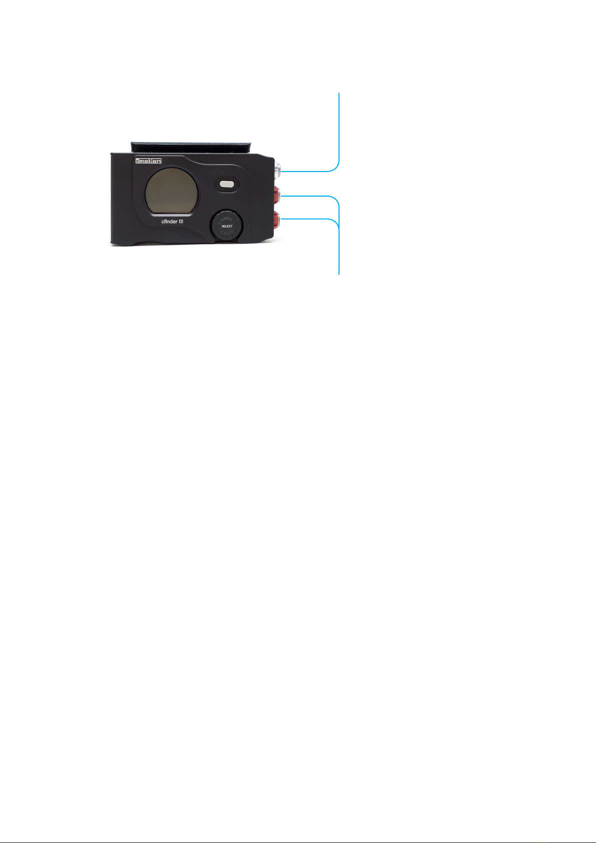
2.1.2. Detailed Component Description
Pos Description
1 display
2 user button
3 menu selection wheel
4 NATO rail
5 serial connector to connect 3rd party equipment
6 LBUS connector to connect LBUS capable peripheral devices or power supply
7 LBUS connector to connect LBUS capable peripheral devices or power supply
8measurement laser (invisible class 1 laser for distance measurement)
9alignment laser (visible class 2 laser as a pointer, representing the invisible measurement laser)
10 cmotion product label including product ID and serial number
11 laser type label
12 laser safety label
13 mounting cube with 3/8” UNC-16 bushing
14 M3 bushing for NATO rail (Allen key, size 2mm required)
1
2
3
5
4
6
7
8 9
10
11
12
13 14

page 8/24
cnder III – User Guide – 01/2017
2.1.4. Technical specications
Power supply: 7,5 - 35 V DC
Power consumption: max. 4 W
Weight: 538 g (1.19 lbs), with reector sight; 331 g (0.73 lbs),
without reector sight
Dimensions: 101 x 52 x 56 mm (3.97 x 2.05 x 2.21 inches),
without reector sight
Display size: 31 x 26 mm (1.22 x 1.02 inches)
Display resolution: 240 x 206 px
Temperature range: -10°C to +60°C
Laser type / Wavelength: Laser diode λ 655 nm & 905 nm
Op.mode/ Power: cw (655 nm), pulsed (905 nm)
Pmax: <0,6 mW (655 nm) 306 nJ/Pulse (905 nm)
Measuring range: 1 - 150 m; approx. 3.3 - 492 ft (depending on environmental
conditions / target surface, color and reectivity)
Accuracy: +/- 5 cm; approx. +/- 2 inches (depending on environmental
conditions / target surface, color and reectivity)
Speed of measurement: 300x / second
Laser divergence:
dist (m) beam size: width x height (mm)
0 18.0 x 18.0
10 42.7 x 19.2
50 141.5 x 24.2
100 264.9 x 30.4
150 388.4 x 36.5
Interfaces: 2x LBUS interface, 1x serial interface
Norms / Regulations:
ISO IEC EN 60 825-1:2015
FDA ANSI 21 CFR 1040
EU or national EU directive 2006/25/EC // OStrV 2010-07 // TROS-Laser
Classication
Operating mode / Condition Normal operation Teaching / Service Maintance / Repair
Applies to User User Manufacturer
Satises the conditions of laser class 2 2 3B
Eye safety conrmed YES YES only with PSE
Laser safety ocer NO NO YES
Laser safety goggles NO NO YES

page 9/24
cnder III – User Guide – 01/2017
2.1.3. System requirements
In order to tap the full potential of the device, please have all connected units updated to a rmware
equal or higher to those listed below.
Product Firmware
cvolution camin 2M cvolution-caminbasic-3.11.30 or higher
cvolution camin 3M cvolution-camin3m-3.11.25 or higher
cvolution camin 4M cvolution-caminbasic-3.11.30 or higher
cvolution camin 8M cvolution-caminbasic-3.11.30 or higher
cvolution hand unit* cvolution-handunit-3.11.29 or higher
compact hand unit** compact-2017_01 or higher
cworld *** cworld-v1.6.0 or higher
cdistance cdistance-3.8.4 or higher
ARRI Alexa Plus available with ARRI software release from Q1 2017
ARRI Alexa Mini available with ARRI software release from Q1 2017
ARRI UMC-4 available with ARRI software release from Q1 2017
ARRI AMC-1 available with ARRI software release from Q1 2017
ARRI WCU-4**** available with ARRI software release from Q1 2017
* works in combination with cvolution camin 2M, 3M, 4M or 8M only
** works in combination with compact LCS camin and cdistance only (limited functions)
*** works in combination with cvolution camin 2M, 3M, 4M, 8M or compact LCS camin
**** works in combination with ARRI Alexa Plus, Alexa Mini, UMC-4 or AMC-1 only

page 10/24
cnder III – User Guide – 01/2017
2.2. Reector sight
2.2.1. Main component overview
The reector sight uses a small light which is projected onto a curved semi-transparent mirror.
From there the light is reected towards the operators eye. The reector sight can be attached to
the NATO rail of cnder III easily (Allen key, size 3 mm required). For further operation the target
mark (red/green spot) of the reector sight needs to be aligned to the measuring laser which is
represented by the visible alignment laser of cnder III. After alignment the operator can target and
track objects easily referring to the superimposed marker within the reector sight while lming.
Note:
This red/green spot reected from the semi-transparent mirror is not harmful to the human eye and
can be watched without any safety precautions.
2.2.2. Detailed component description (Image 2: Reector sight)
1. tilt adjustment wheel with protective cap (athead screwdriver required)
2. pan adjustment wheel with protective cap (athead screwdriver required)
3. rotary switch to activate target mark
• at position “G“ the target mark is o
• turn the rotary switch clockwise to activate GREEN target mark in 1-5 light intensities
• at position “R“ the target mark is o
• turn the rotary switch clockwise to activate RED target mark in 1-5 light intensities
4. NATO rail slide mount using M4 screws (Allen key, size 3 mm required)
Battery:
The target mark of the reector sight is powered by a 3 V lithium coin style battery (CR 2032).
Replace the battery if the target mark dims or does not light up at all. To install the battery, unscrew
the battery cap on top of the rotary switch and insert the battery with the positive terminal facing
up. Screw the battery cap back on again.
Note:
Always remember to turn o the target mark of the reector sight (position “G“ or “R“) once you are
nished using it.
Image 2: Reector sight Image 3: Reector sight mounted on cnder III
2
4
3 1
page 11/24
cnder III – User Guide – 01/2017
3. System environment overview
Serial interface to 3rd parties
To ARRI ALEXA Plus via UDM to ALEXA cable (K2.65261.0)
To ARRI ALEXA Mini* only available via LCUBE at time of writing
• connect serial connector of cnder III via UDM to UMC/CUB-1 cable (K2.65144.0) to serial
connector of the LCUBE CUB-1
• connect LCUBE CUB-1 via LCB (Le m4p, Le m4p) cable to Alexa Mini
To ARRI UMC-4 via UDM to UMC/CUB-1 cable (K2.65144.0)
LBUS interface to LBUS devices
• To cvolution camin 3M via LCB (Le m4p, Le m4p) cable
• To cdistance via LCB (Le m4p, Le m4p) cable
• To Alexa Mini* through the end motor of the cforce motor daisy-chain connection via LCB (Le m4p,
Le m4p) cable
• TTo cvolution camin 2M, 3M, 4M, 8M and cworld via LCB-7 cable (Le m4p, Le m8p)
• To cforce, cforce plus, cforce mini motor, via LCB (Le m4p, Le m4p) cable
• To power (LBUS power supply options can be found in the cmotion cable guide at
www.cmotion.eu)
* direct compatibility with ARRI Alexa Mini through the LBUS protocol will be possible with ARRI Alexa Mini rmware released
Q1 2017
Serial interface to 3rd parties
LBUS interface to LBUS devices

page 12/24
cnder III – User Guide – 01/2017
4. System structure and navigation
4.1. General navigation
• double click selection wheel to enter menu
• rotate selection wheel clockwise / anti-clockwise to scroll up / down
• single click selection wheel to enter sub menus
• single click selection wheel to conrm selection
• press user button to cancel selection
• press user button to leave sub menu to the next higher menu
• press and hold user button to leave menu from the rst level sub menu
4.2. Menu tree overview
main level 1st level sub menu 2nd level sub menu 3rd level sub menu 4th level sub menu
main screen /
2nd screen overlay main unit imperial
metric
view distance
tacho
display brightness use select wheel to
adjust
stealth o
on
distance oset use select wheel to
adjust
limit max use select wheel to
adjust
limit min use select wheel to
adjust
sensitivity use select wheel to
adjust
autofocus o
on
laser pointer o
on
button no function
laser pointer
autofocus
system unit
system serial o
on
about factory reset
info screen

page 13/24
cnder III – User Guide – 01/2017
4.3. Detailed menu functions
unit: - use selection wheel to choose between “imperial“ and “metric“ scale units
view: - use selection wheel to choose between “distance“ and “tacho“ view
distance view: - shows measured distance values only
tacho view: - if limits are set, tacho view visualizes limit range by a bright green
scale
- a blue needle indicates the currently measured value
brightness: - use selection wheel to adjust display brightness
stealth: - use selection wheel to turn stealth mode “on“ or “o“
- stealth mode turns the display o once you exit to the main menu
- double click selection wheel to reenter menu and to turn display on again
- to leave stealth mode, select stealth mode “o“
- if the unit is powered down, stealth mode is set to “o“ as default
oset: - use selection wheel to enter the measured oset from the datum line of cnder III
to the sensor plane of the camera
- if cnder III is mounted in front of the sensor plane, dial in positive values
- if cnder III is mounted behind the sensor plane, dial in negative values
Note: Oset can be adjusted in increments of +/- 0,5cm (+/- 0.25 inches) up to
+/- 50cm (+/- 20 inches)
limit max: - use selection wheel to enter a far distance limit
- if in AF mode, focus will not be adjusted for measurements beyond this limit
limit min: - use selection wheel to enter a close distance limit
- if in AF mode, focus will not be adjusted for measurements below this limit
Note: Please also refer to section 6.1.2. in this manual.
sensitivity: - use selection wheel to increase or decrease sensor sensitivity
- sensitivity adjusts the reaction behaviour of the readout on the display and the
motor response
Note: The lower the sensitivity, the more stable the distance display and the
smoother the motor movement. Please refer to section 6.1.3. in this manual.
autofocus: - use selection wheel to turn autofocus “on“ or “o“
- if turned on through cnder III, activates autofocus permanently (other options are
available using a cvolution hand unit, please refer to the latest cvolution user guide)
Note: In order to use autofocus with a cvolution system, a lens le needs to be
loaded in the camin, a lens motor needs to be connected, engaged with the lens
and assigned to focus. For further information on how to create lens data, please
refer to the cvolution user guide and the cworld user guide.
laser pointer: - use selection wheel to turn laser pointer “on“ or “o“
- laser pointer will turn o after 30 seconds automatically
- during those 30 seconds you can turn it o manually at any time by selecting “o“
button: depending on user requirements the user button can be congured to
- “no function“
- “laser pointer“, to activate the laser pointer by press and hold command
- “autofocus“, to activate and deactivate AF by single click command
- “system unit“, to change scale units between metric and imperial by single click
command

page 14/24
cnder III – User Guide – 01/2017
serial out: - use selection wheel to turn the serial interface output “on“ or “o“
- if cnder III is connected through its serial interface with compatible 3rd party
devices, turn the serial output “on“
- if cnder III is connected through its LBUS interface using the LBUS protocol, turn
the serial output “o“
factory reset: - double click selection wheel to reset manufacturer settings
about: - contains information about serial number, rmware version, boot loader version,
hardware revision number and rmware build
Note: For any support requests please provide information listed in the about menu

page 15/24
cnder III – User Guide – 01/2017
4.4. Second screen overlay
Besides the main screen the display accommodates a second screen with additional information
• turn the selection wheel by one step in any direction to activate the second screen overlay
• turn the selection wheel by another step to deactivate the second screen overlay
limit: indicates that a min or max limit is active, other than default values
(limit min=0, limit max=inf)
AF: indicates if autofocus is on or o
sens: indicates how sensitivity is adjusted
oset: displays the oset between the cnder III‘s datum line and the camera‘s sensor plane
sensor: lights up if no valid measurement is possible
Note:
Usually cnder III covers a maximum distance of 150 m (492 ft). Depending on target surface, color or
reectivity, the measurement may be restricted. If no valid measurement is possible or target is out of
range, the information “sensor“ will light up on the main and second screen overlay.
Ambient illumination does not aect the range of cnder III. It works in bright sunlight as well as in
complete darkness. Nevertheless weather phenomenons like heavy rain, snowfall or fog may reduce
the maximum range of cnder III and airborne particles may be detected as new targets.
Image 4: cnder III main screen
(tacho view)
Image 5: cnder III second screen overlay
(tacho view)

page 16/24
cnder III – User Guide – 01/2017
5. System set-up and operation
5.1. Aligning the reector sight to cnder III using the internal target mark
1. mount the reector sight to the NATO rail of cnder III (Allen key, size 3 mm required)
2. remove the protective caps for the pan and tilt adjustment wheel of the reector sight
3. activate a target mark by turning the rotary switch of the reector sight
4. activate the alignment laser of cnder III
5. turn the pan adjustment wheel (left/right) until the target mark matches the laser spot
projected by the alignment laser horizontally (athead screwdriver required)
6. turn the tilt adjustment wheel (left/right) until the target mark matches the laser spot
projected by the alignment laser vertically (athead screwdriver required)
7. replace on the protective caps for the pan and tilt adjustment wheel of the reector sight
Note:
Projecting the alignment laser onto a target as far away as possible improves the alignment if tracking
far distance objects. Nevertheless, aligning onto a far distance target creates a small vertical parallax
between the target mark of the reector sight and the actual position of the measuring laser spot of
approx. 6,5 cm (approx. 2.5 inches) in close distance.
Due to light conditions the laser spot of the alignment laser might not be visible in far distance. In order
to be independent of light conditions you can align the reector sight using the sensor feedback of
cnder III or cdistance (if available). (please refer to section 6.2.1. in this manual)
5.2. Mounting cnder III on the camera
Common fastening tools can be used to mount cnder III to the camera. Optional fastening tools are
available from cmotion.
• in order to avoid horizontal parallax, mount cnder III centered along the optical axis, above
or below the camera lens.
• in order to minimize vertical parallax, mount cnder III as close as possible to the lens
vertically
Note:
Minor horizontal or vertical osets relative to the optical axis will not cause signicant parallax hence
measurement precision. Nevertheless, parallax may cause issues when tracking a precise object from
far to close.
cnder III can be mounted along the optical axis of the lens, behind or in front of the camera‘s sensor
plane. This oset can be compensated using the oset function in the systems menu.
Warning:
In order to allow smooth operation, the measuring laser should not be blocked by any camera
parts or accessories. Especially if you want to cover a range from far to close distance, we recommend
to mount cnder III in line with the matte box.

page 17/24
cnder III – User Guide – 01/2017
5.3. Aligning cnder III to the optical axis of the lens
5.3.1. Using the reector sight
1. align the reector sight to cnder III (please refer to section 5.1. or 6.2.1. in this
manual)
2. activate a target mark by turning the rotary switch of the reector sight
3. activate a center cross on your camera
4. if using a zoom lens, zoom in all the way
5. aim your camera at a far-away target
6. slightly pan/tilt cnder III until the target mark of the reector sight matches the
same point as the center cross on your camera
5.3.2. Using the alignment laser
1. activate the alignment laser of cnder III
2. activate a center cross on your camera
3. if using a zoom lens, zoom in all the way
4. aim your camera at a far-away target
5. slightly pan/tilt cnder III until the spot of the alignment laser matches the same
point as the center cross on your camera
Note:
Due to light conditions the laser spot of the alignment laser might not be visible in far distance. In
order to be independent of light conditions you can align cnder III to the optical axis of the lens
using its sensor feedback or the sensor feedback of cdistance (if available). (please refer to section
6.2.2. in this manual)
All methods described above are aligning the measuring laser to the center of the lens. Under
certain circumstances you may want the measuring laser to be o center. If so, please align cnder
III accordingly.
Aligning onto a far distance object improves the alignment if tracking far distance targets.
Nevertheless, aligning onto a far distance target creates a small vertical parallax between the center
cross and the actual position of the measuring laser in close distance. Although this parallax will
not have any signicant eect on the measurement precision, it may cause issues when tracking a
precise object from far to close.
5.4. Using cnder III separate from the camera
cnder III can be used on a tripod separate from the camera. In this conguration the operator can pan
and tilt cnder III independently from the camera to track a moving target. In order to give the operator
reference of the lasers measuring spot you should use cnder III with the reector sight in this
conguration only (please refer to section 5.1. or 6.2.1. in this manual).
Note:
The tripod does not need to be positioned in line with the lm plane. This oset can be compensated
using the oset function within the systems menu (please refer to section 6.1.1. in this manual).
Although in this conguration the risk of vertical parallax can be eliminated by mounting cnder III at the
same height as the camera lens, keeping cnder III as close to the lens as possible will reduce the risk
of horizontal parallax.

page 18/24
cnder III – User Guide – 01/2017
6. Practical system operation
6.1. System settings
6.1.1. Oset
The oset function allows you to consider the dierence between the mounting point of cnder III
and the sensor plane of the camera.
• measure the distance from the datum line of cnder III to the sensor plane of your camera
• enter the measured distance into the cnder III oset menu
• if cnder III is mounted in front of the sensor plane enter positive values
• if cnder III is mounted behind the sensor plane enter negative values
6.1.2. Limits
The limit function allows you to dene your range of interest. If in AF mode, focus will be adjusted
for this range only.
limit max:
• use selection wheel to enter a far distance limit
• if in AF mode, focus will not be adjusted for measurements beyond this limit
limit min:
• use selection wheel to enter a close distance limit
• if in AF mode, focus will not be adjusted for measurements below this limit
The second screen overlay will show “limit“ if any limits other than default values (limit min=0, limit
max=inf) are set. Tacho view visualizes the set limit range by a bright green scale.
6.1.3. Sensitivity
The invisible laser used in cnder III makes 300 measurements every second. To make this rapid di-
stance information more suitable for both viewing and motorised lens control, cnder III calculates
an average distance that is then displayed on the screen and used to control the focus motor when
autofocus is active.
Sensitivity allows you to increase or decrease the rate at which the ‚average‘ value is calculated.
By increasing sensitivity, cnder III will display an increased number of distance values per second
and adjust the motor position accordingly (= faster / snap reaction).
By decreasing sensitivity, cnder III will display fewer distance values per second and adjust the
motor position accordingly (= slower / smoother reaction).
Note: To track a fast moving target, increase sensitivity for a faster motor response. To track a slow
moving or xed target, reduce sensitivity for a smoother motor response.

page 19/24
cnder III – User Guide – 01/2017
6.1.4. Autofocus
The autofocus function will seamlessly match distance measurement data from the cnder III with
lens data from the camin to control the focus scale of the lens automatically.
If autofocus “on“ is selected within the cnder III menu, focus will be adjusted permanently until
turned o again.
Autofocus can be activated through a cvolution hand unit as well. Using a cvolution hand unit
various autofocus trigger options including toggle and mark are available. (For further information,
please refer to the latest cvolution user guide)
Note:
In order to use autofocus with a cvolution system, a lens le needs to be loaded in the camin,
a lens motor needs to be connected, engaged with the lens and assigned to focus. For further
information on how to create lens data, please refer to the cvolution user guide and the cworld user
guide.
6.2. Practical Tips and Tricks
Due to light conditions the laser spot of the alignment laser might not be visible in far distance. In
order to be independent of light conditions you can use the cnder III sensor feedback to align the
reector sight to cnder III as well as to align cnder III to the optical axis of the lens. cdistance (if
available) shows the same sensor feedback and can be used for these practical alignment methods
as well.
6.2.1. Aligning the reector sight to cnder III using the sensor feedback
1. mount the reector sight to the NATO rail of cnder III (Allen key, size 3 mm required)
2. mount cnder III onto a camera tripod
3. remove the protective caps of the reector sight
4. activate a target mark by turning the rotary switch of the reector sight
5. aim at a xed horizontal and vertical target as far away as possible but within the range
of cnder III (e.g. aim the tip of a building against the sky)
6. pan the tripod head until the sensor does not get any feedback, measuring out of
range (e.g. hitting the sky)
7. pan back slightly until you have a rst measurement from the target (e.g. vertical
edge of the building) and x the pan axis of your tripod head
8. turn the pan adjustment wheel of the reector sight (left/right) until the target mark
matches your target horizontally (e.g. vertical edge of the building) (athead
screwdriver required)
9. tilt the tripod head until the sensor does not get any feedback, measuring out of
range (e.g. hitting the sky)
10. tilt back slightly until you have a rst measurement from the target (e.g. horizontal
edge of the building) and x the tilt axis of your tripod head
11. turn the tilt adjustment wheel of the reector sight (left/right) until the target mark
matches your target vertically (e.g. horizontal edge of the building) (athead
screwdriver required)
12. replace the protective caps of the reector sight

page 20/24
cnder III – User Guide – 01/2017
6.2.2. Aligning cnder III to the optical axis of the lens using the sensor feedback
1. activate a center cross on your camera
2. if using a zoom lens, zoom in all the way
3. aim at a xed horizontal and vertical target as far away as possible but within the range
of cnder III (e.g. the tip of a building against the sky)
4. once the center cross of your camera is matching the horizontal and vertical edges
of your target, lock your camera tripod
5. pan cnder III until the sensor does not get any feedback, measuring out of range
(e.g. hitting the sky)
6. pan cnder III back slightly until you have a rst measurement from the target
(e.g. vertical edge of the building)
7. tilt cnder III until the sensor does not get any feedback, measuring out of range
(e.g. hitting the sky)
8. tilt cnder III back slightly until you have a rst measurement from the target
(e.g. horizontal edge of the building)
9. Lock o the cnder III fastening tool
6.3. Maintenance
If not in use, cnder III should be kept in a clean and dry place.
The front lenses of cnder III are optical elements and should be treated as such.
The lenses should be kept dry and dust free.
In order to avoid scratching the lenses always remove dust with compressed air before cleaning with a
soft cloth.
In order to keep your unit up-to-date, please check cmotion website http://cmotion.eu/show/support
regularly for the latest rmware updates available and also refer to section 7. in this manual.
Warning:
Dust particles or ngerprints may cause false or unstable readings.
Note:
cmotion can guarantee successful performance only if original cmotion components and accessories
are used.
Table of contents
Other cmotion Camera Accessories manuals


