cmotion cPRO hand unit User manual

All content © 2018, cmotion GmbH. All specications are subject to change without further notice.
http://www.cmotion.eu
page 1 of 80
v1.1 | November, 2018
Software Release Package v1.1
cPRO hand unit
User Guide

All content © 2018, cmotion GmbH. All specications are subject to change without further notice.
http://www.cmotion.eu
page 2 of 80
Imprint
Copyright
Copyright © 2018 cmotion GmbH (cmotion).
All rights reserved. No portions of this document may be reproduced without prior written
consent of cmotion GmbH.
Specications are subject to change without notice. Errors, ommissions, and
modications excepted.
For further assistance
cmotion GmbH
Wiedner Hauptstraße 135/B3
1050 Wien
Fbnr.: FN220240H – HG Wien
UID-Nr.: ATU 54026806
http://www.cmotion.eu
+43 1 7891096
This USER GUIDE applies to the following product:
K2.0016602 cPRO hand unit with Software Release Package v1.1
Document revision history: v1.1
Release Date: 15.11.2018

All content © 2018, cmotion GmbH. All specications are subject to change without further notice.
http://www.cmotion.eu
page 3 of 80
Disclaimer
Before using the products described in this manual, be sure to read and understand all
the respective instructions.
The cmotion Software Release Package v1.1 cPRO hand unit is only available to
commercial customers. By utilization, the customer agrees that the cPRO hand unit or
other components of the system are deployed for commercial use only. Otherwise the
customer must contact cmotion before utilization.
While cmotion endeavors to enhance the quality, reliability and safety of their products,
customers agree and acknowledge that the possibility of defects thereof cannot be
eliminated entirely.
To minimize the risk of damage to property or injury (including death) to persons arising
from defects in the products, customers must incorporate sucient safety measures in
their work with the system and heed the stated canonic use.
cmotion or its subsidiaries do not assume any responsibility for losses incurred due to
improper handling or conguration of the cPRO hand unit or other system components.
cmotion assumes no responsibility for any errors that may appear in this document. The
information is subject to change without notice.
For product specication changes after this manual was published, refer to the
latest published cmotion data sheets or release notes, etc., for the most up-to-date
specications. Not all products and/or types are available in every country. Please check
with your cmotion sales representative for availability and additional information.
Neither cmotion nor its subsidiaries assume any liability for infringement of patents,
copyrights or other intellectual property rights of third parties by or arising from the
use of cmotion products or any other liability arising from the use of such products. No
license, express, implied or otherwise, is granted under any patents, copyrights or other
intellectual property right of cmotion or others.
cmotion or its subsidiaries expressly exclude any liability, warranty, demand or other
obligation for any claim, representation, cause, action, or whatsoever, express or implied,
whether in contract or not, including negligence, or incorporated in terms and conditions,
whether by statue, law or otherwise. In no event shall cmotion or its subsidiaries be
liable for or have a remedy for recovery of any special, direct, indirect, incidental, or
consequential damages, including, but not limited to lost prots, lost savings, lost
revenues or economic loss of any kind or for any claim by a third party, downtime, good-
will, damage to or replacement of equipment or property, any cost or recovery of any
material or goods associated with the assembly or use of our products, or any other
damages or injury of the persons and so on or under any other legal theory.
In the event that one or all of the foregoing clauses are not allowed by applicable law, the
fullest extent permissible clauses by applicable law are validated

All content © 2018, cmotion GmbH. All specications are subject to change without further notice.
http://www.cmotion.eu
page 4 of 80
Table of Contents
1. For your safety............................................................................................................ 8
2. Audience and intended use...................................................................................... 10
3. Scope of delivery and warranty................................................................................ 10
4. Introduction .............................................................................................................. 11
4.1. LBUS connector................................................................................................. 12
4.2. CAM interface..................................................................................................... 12
5. cPRO hand unit hardware layout.............................................................................. 13
5.1. Hardware layout overview .................................................................................. 13
5.2. Control interface................................................................................................. 14
5.2.1. Knob............................................................................................................ 14
5.2.1.1. Mechanical hard stops .................................................................... 14
5.2.1.2. Panic button .................................................................................... 15
5.2.1.3. Pre-marked focus rings ................................................................... 15
5.2.1.4. Datum line........................................................................................ 15
5.2.1.5. Knob illumination and status LEDs.................................................. 15
5.2.2. Slider ........................................................................................................... 16
5.2.2.1. Pre-marked iris strips....................................................................... 16
5.2.2.2. Slider illumination and status LEDs ................................................. 16
5.2.3. Joystick ....................................................................................................... 17
5.2.3.1. Position indicator display................................................................. 17
5.2.3.2. Joystick status LED ......................................................................... 17
5.2.4. Thumb wheel............................................................................................... 18
5.2.5. Buttons / camera status LED ...................................................................... 18
5.2.5.1. REC button and camera status LED................................................ 19
5.2.5.2. User buttons .................................................................................... 19
5.2.5.3. Back button ..................................................................................... 20
5.2.5.4. Menu buttons................................................................................... 20
5.2.5.4.1. MB2 (QUICK NAV) ..................................................................20
5.2.5.4.2. Quick navigation between main screens................................21
5.2.5.4.3. Quick navigation main screens to adjustment menu .............21
5.2.5.5. HOME button................................................................................... 21
5.2.5.6. System status LED .......................................................................... 21
5.2.6. Touch screen ............................................................................................... 22

All content © 2018, cmotion GmbH. All specications are subject to change without further notice.
http://www.cmotion.eu
page 5 of 80
6. cPRO hand unit software layout............................................................................... 23
6.1. GUI main screen overview.................................................................................. 23
6.1.1. MAIN screen................................................................................................ 25
6.1.2. FIZ main screen........................................................................................... 25
6.1.2.1. Focus main screen........................................................................... 26
6.1.2.2. Iris main screen................................................................................ 26
6.1.2.3. Zoom main screen........................................................................... 27
6.1.2.4. Lens information main screen.......................................................... 27
6.1.3. Camera main screen ................................................................................... 27
6.1.4. Rangender main screens........................................................................... 28
6.1.4.1. Rangender overview screen .......................................................... 28
6.1.4.2. Rangender settings screen ............................................................ 29
6.1.5. Buttons main screens.................................................................................. 29
6.1.6. Controls main screen .................................................................................. 30
6.1.7. Motors main screens................................................................................... 31
6.2. Adjustment menu ............................................................................................... 32
6.2.1. Adjustment menu overview......................................................................... 32
6.2.2. Adjustment menu navigation....................................................................... 33
6.2.3. Menu ........................................................................................................... 33
6.2.3.1. MAIN................................................................................................ 34
6.2.3.1.1. Radio ......................................................................................34
6.2.3.1.1.1. RF .........................................................................34
6.2.3.1.1.2. Channel ................................................................34
6.2.3.1.1.3. Region ..................................................................34
6.2.3.1.2. Unit .........................................................................................35
6.2.3.1.3. Brightness...............................................................................36
6.2.3.1.3.1. Auto activate.........................................................36
6.2.3.1.3.2. Auto brightness ....................................................36
6.2.3.1.3.3. Display..................................................................36
6.2.3.1.3.4. Keypad brightness ...............................................36
6.2.3.1.3.5. Knob brightness ...................................................36
6.2.3.1.3.6. Slider brightness...................................................37
6.2.3.1.3.7. Joystick brightness...............................................37
6.2.3.1.4. Vibration..................................................................................37
6.2.3.1.4.1. Keypad .................................................................37
6.2.3.1.4.2. Touch screen ........................................................37
6.2.3.1.4.3. Thumb wheel ........................................................37
6.2.3.1.5. Touch screen ..........................................................................37
6.2.3.1.6. Thumb wheel ..........................................................................38
6.2.3.1.7. Stealth mode all......................................................................38
6.2.3.2. CONTROLS ..................................................................................... 38
6.2.3.2.1. Knob .......................................................................................39
6.2.3.2.1.1. Control..................................................................39

All content © 2018, cmotion GmbH. All specications are subject to change without further notice.
http://www.cmotion.eu
page 6 of 80
6.2.3.2.1.2. Knob direction ......................................................39
6.2.3.2.1.3. Pre-marked rings..................................................39
6.2.3.2.1.4. Lock......................................................................40
6.2.3.2.2. Slider.......................................................................................40
6.2.3.2.2.1. Control..................................................................40
6.2.3.2.2.2. Pre-marked strips.................................................40
6.2.3.2.2.3. Lock......................................................................41
6.2.3.2.3. Joystick ..................................................................................41
6.2.3.2.3.1. Control..................................................................41
6.2.3.2.3.2. Sensitivity .............................................................41
6.2.3.2.3.3. Speed ...................................................................42
6.2.3.2.3.4. Lock......................................................................42
6.2.3.3. LENS................................................................................................ 42
6.2.3.3.1. Load........................................................................................43
6.2.3.3.2. Unload ....................................................................................43
6.2.3.3.3. Create .....................................................................................44
6.2.3.3.3.1. Motor calibration ..................................................44
6.2.3.3.3.2. Select manufacturer .............................................45
6.2.3.3.3.3. Set lens name.......................................................45
6.2.3.3.3.4. Set serial number .................................................46
6.2.3.3.3.5. Focus imperial / metric selection .........................46
6.2.3.3.3.6. Scale calibration ...................................................47
6.2.3.3.3.7. Focus scale ..........................................................47
6.2.3.3.3.8. Iris scale................................................................49
6.2.3.3.3.9. Zoom scale...........................................................50
6.2.3.3.3.10. Save.....................................................................52
6.2.3.3.4. Edit .........................................................................................53
6.2.3.3.5. Delete .....................................................................................54
6.2.3.3.6. Lens view................................................................................54
6.2.3.3.7. Set iris.....................................................................................55
6.2.3.3.8. Set zoom ................................................................................55
6.2.3.3.9. Circle of confusion..................................................................55
6.2.3.4. MOTORS ......................................................................................... 56
6.2.3.4.1. Calibration all..........................................................................56
6.2.3.4.2. Motor settings ........................................................................57
6.2.3.4.2.1. Axis.......................................................................57
6.2.3.4.2.2. Torque...................................................................57
6.2.3.4.2.3. Direction ...............................................................57
6.2.3.4.2.4. Ramp ....................................................................58
6.2.3.4.2.5. Calibrate ...............................................................58
6.2.3.4.3. Stealth mode ..........................................................................58
6.2.3.5. RANGEFINDER................................................................................ 59
6.2.3.5.1. Oset .....................................................................................59

All content © 2018, cmotion GmbH. All specications are subject to change without further notice.
http://www.cmotion.eu
page 7 of 80
6.2.3.5.2. Limits ......................................................................................59
6.2.3.5.3. Sensitivity ...............................................................................60
6.2.3.5.4. Autofocus ...............................................................................60
6.2.3.5.5. Laser pointer...........................................................................60
6.2.3.6. BUTTONS ........................................................................................ 61
6.2.3.6.1. Assignable user buttons.........................................................61
6.2.3.6.2. User button functions.............................................................62
6.2.3.7. ABOUT............................................................................................. 63
6.2.3.7.1. cPRO hand unit ......................................................................63
6.2.3.7.2. LBUS devices .........................................................................64
6.2.3.7.3. Firmware update.....................................................................64
6.2.3.7.4. Factory reset...........................................................................66
7. Setting up the cPRO system .................................................................................... 67
7.1. using the cPRO motor........................................................................................ 67
7.1.1. Mounting and connecting cables:............................................................... 67
7.1.2. Setting up cPRO hand unit and cPRO motor ............................................. 67
7.1.2.1. Establishing a wireless RF connection ............................................ 67
7.1.2.2. Assigning the cPRO and other motor’s control axis........................ 68
7.1.2.3. Calibrating the cPRO / cforce motors ............................................. 68
7.2. using the cPRO camin with cforce motors......................................................... 69
7.2.1. Mounting and connecting cables:............................................................... 69
7.2.2. Setting up cPRO hand unit and cPRO camin ............................................. 69
7.2.2.1. Establishing a wireless RF connection ............................................ 69
7.2.2.2. Assigning the motor’s control axis................................................... 70
7.2.2.3. Calibrating the cforce motors .......................................................... 70
8. Compatibility............................................................................................................. 71
9. Power connection and disconnection ...................................................................... 71
9.1. Power connection .............................................................................................. 71
9.2. Power disconnection.......................................................................................... 71
10. Appendix .................................................................................................................. 72
10.1. Antenna connector ............................................................................................. 72
10.2. Specications..................................................................................................... 72
10.3. Dimensions and weight ...................................................................................... 73
10.4. Pinouts ............................................................................................................... 74
10.5. Part numbers...................................................................................................... 74
10.6. Service contacts................................................................................................. 78
10.7. International declarations ................................................................................... 79
All content © 2018, cmotion GmbH. All specications are subject to change without further notice.
http://www.cmotion.eu
page 8 of 80
1. For your safety
Before use, please ensure that all users comprehensively read, understand, and follow the
instructions in this document.
Risk levels and alert symbols
Safety warnings, safety alert symbols, and signal words in these instructions indicate dierent
risk levels:
Danger!
DANGER indicates an imminent hazardous situation which, if not avoided, will result in death
or serious injury.
Warning!
WARNING indicates a potentially hazardous situation which, if not avoided, may result in
death or serious injury.
CAUTION!
CAUTION indicates a potentially hazardous situation which, if not avoided, may result in minor
or moderate injury.
NOTICE
NOTICE explains practices not related to physical injury. No safety alert symbol appears with
this signal word.
Note: Provides additional information to clarify or simplify a procedure.

All content © 2018, cmotion GmbH. All specications are subject to change without further notice.
http://www.cmotion.eu
page 9 of 80
Vital precautions
Danger!
Risk of electric shock and re!
Short-circuits may result in serious damage to equipment, injury or death.
Before use, read and follow all valid instructions.
Use solely and exclusively as described in the instructions.
Never open. Never insert objects unless instructed to do so. E.g. battery, USB.
For operation, always use a power source as indicated in the instructions.
Always unplug the cable by gripping the plug, not the cable.
Never try to repair. All repair work should be done by a qualied cmotion Service Center.
Never remove or deactivate any safety equipment (incl. warning stickers or paintmarked
screws).
Always protect from moisture, cold, heat, dirt, vibration, shock, or aggressive substances.
Danger!
Risk of re!
Short-circuits and back currents to power supplies/batteries may result in serious damage to
equipment, injury or death.
Always use original ARRI/cmotion LBUS cables to external power sources (D-Tap, XLR)!
ARRI/cmotion LBUS cables to external power sources provide a protection circuit to prevent
back currents to power supplies/batteries.

All content © 2018, cmotion GmbH. All specications are subject to change without further notice.
http://www.cmotion.eu
page 10 of 80
2. Audience and intended use
NOTICE
The product is solely and exclusively available for commercial customers and shall be used by
skilled personnel only. Every user should be trained according to cmotion guidelines. Use the
product only for the purpose described in this document. Always follow the valid instructions
and system requirements for all equipment involved.
Note: The cPRO hand unit is solely and exclusively for use on professional camera setups.
3. Scope of delivery and
warranty
NOTICE
Product and packaging contain recyclable materials. Always store, ship, and dispose of
according to local regulations.
cmotion is not liable for consequences from inadequate storage, shipment or disposal.
Delivery
On delivery, please check that the package and content are intact. Never accept a damaged or
incomplete delivery. A complete delivery includes:
■cPRO hand unit unit with antenna
■Plain white focus ring for cPRO hand unit
■Plain white iris strip for cPRO hand unit
■ctruss - connection point for cstrap
■User manual download card
■Original packaging
Warranty
For scope of warranty, please ask your local cmotion Service Partner. cmotion is not liable
for consequences from inadequate shipment, improper use or damage through third-party
products.
All content © 2018, cmotion GmbH. All specications are subject to change without further notice.
http://www.cmotion.eu
page 11 of 80
4. Introduction
The cPRO hand unit is the wireless hand-held control unit of the cPRO lens control system with
an integrated red-coded cmotion radio module. With its user friendly and intuitive interface the
cPRO hand unit is lightweight and sets new standards in both design and ergonomics.
The focus knob oers an ergonomic grip with a ngertip concave mold and mechanical hard
stops.
6 user buttons provide quick access to cPRO’s extensive features. Iluminated key elements
(focus marker ring, iris slider strip and buttons) oer ideal operation even in dark environments.
The capacative touch display shows live lens and camera information.
The asymmetrical design and comfort grip keeps the hand unit balanced in your hand. Several
well positioned mounting points provide options for third party accessories including quick
release mounts, monitors, etc.
With optional network licensing, up to three cPRO hand units can connect to a cPRO motor /
cPRO camin for split focus, iris and zoom operation (available with Software Release Package
v2.0 / license required for each hand unit). Real-time lens data is available when used with the
cPRO motor / cPRO camin.
Using the LBUS interface, the cPRO hand unit can be hard-wired with up to three additional
cforce motors and other ARRI / cmotion control units including the pan-bar / steady zoom,
ARRI LCUBE-1, LCUBE-2, ARRI Master Grips or cnder III.

All content © 2018, cmotion GmbH. All specications are subject to change without further notice.
http://www.cmotion.eu
page 12 of 80
Main features:
■Ergonomic and balanced design
■Extensive software features for creative FIZ control
■Supports lens data with cPRO motor / cPRO camin
■Touch display for menu navigation and settings
■Intuitive thumb wheel for menu navigation, settings and 4th axis control (available
with Software Release Package v2.0.)
■Illuminated pre-marked focus rings and iris strips with LED status feedback
■Illuminated, user assignable buttons
■Vibrating function
■USB for external power source, updates and transfer of lens les and user settings
■Mounting options for accessories like cstrap, monitor bracket or v-lock plate
■Adjustable mechanical hard stops
■Panic button for mechanical hard stop override
■Integrated cmotion red radio module
■Daisy-chain compatible via LBUS for hard-wired operation
■Lightweight (less than 900g (approx 31 oz) incl. battery and antenna)
4.1. LBUS connector
LBUS is a bus standard designed to allow multiple lens motors and control devices to
communicate with each other. Up to three cforce-type motors can be chain-linked in a row.
Each cforce motor has two identical, bi-directional LBUS interfaces providing power and
control signals to the motor. For hard-wired operation the cPRO hand unit can be connected
to the daisy-chain through its LBUS interface using any LBUS to LBUS cable.
4.2. CAM interface
The cPRO hand unit does not have a CAM interface itself. But, the CAM interface on the cPRO
motor / cPRO camin is also a fully functional LBUS connector. As such, it allows multiple
lens motors and control devices to communicate with each other through K2.0015760 Cable
CAM (7p) - LBUS. Using this cable the cPRO hand unit can also be connected to the daisy-
chain through its LBUS interface for hard-wired operation.
In addition, the CAM interface on the cPRO motor / cPRO camin oers a versitile interface
for camera control. There are several camera interface cables available which, depending
on the camera, oer start-stop control with feedback, camera status, tally and even camera
control. (License required to control camera settings / available with Software Release
Package v2.0).
If a camera is detected in the LBUS daisy-chain, camera data and camera feedback will be
displayed on the cPRO hand unit.

All content © 2018, cmotion GmbH. All specications are subject to change without further notice.
http://www.cmotion.eu
page 13 of 80
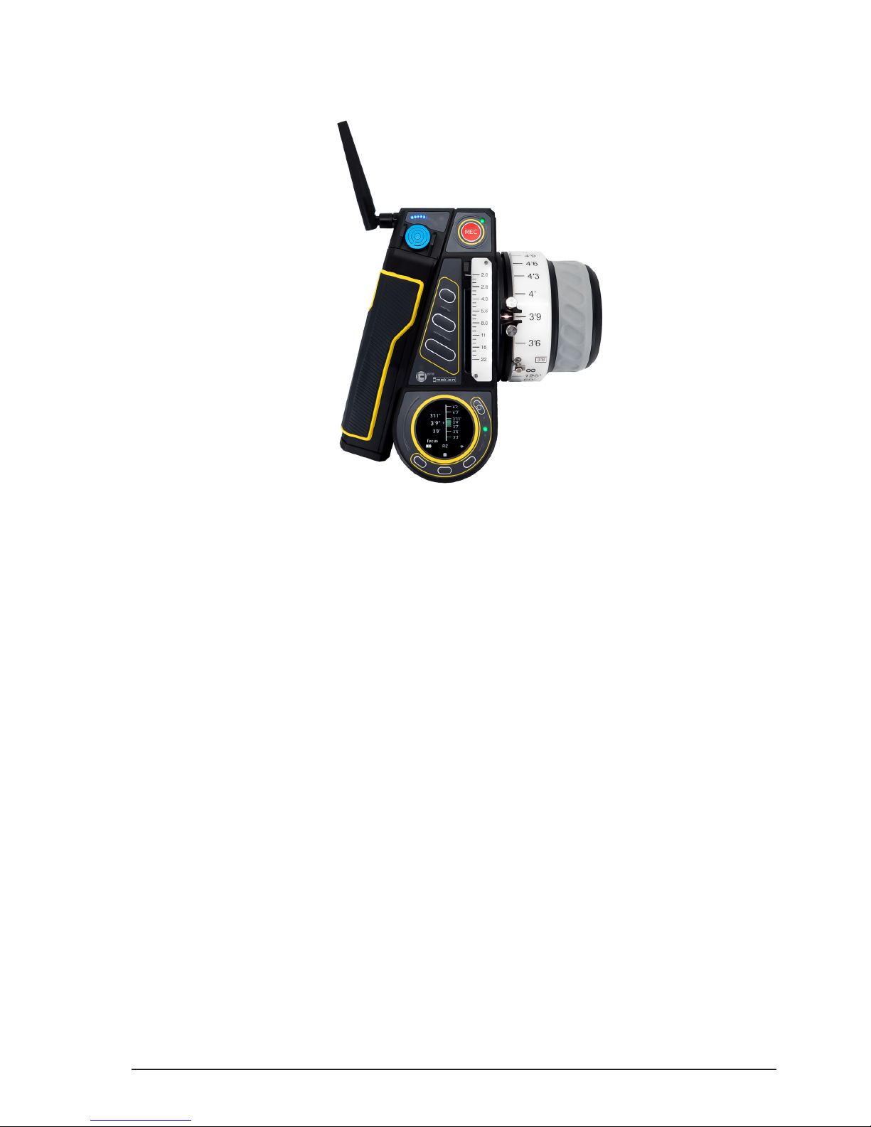
5. cPRO hand unit hardware layout
5.1. Hardware layout overview
1 Joystick
2 User buttons
3 Light sensor
4 Touch display
5 Thumb wheel
6 Menu buttons
7 HOME button
8 Knob
9 Slider
10 REC button
11 Joystick indicator display
12 Back button
1
2
3
4
5 6
7
8
9
10
11
12

All content © 2018, cmotion GmbH. All specications are subject to change without further notice.
http://www.cmotion.eu
page 14 of 80
5.2. Control interface
5.2.1. Knob
1 Mechanical hard stops
2 Panic button
3 Pre-marked focus ring
4 Fingertip concave mold
5 Anti-slip grip
6 Datum line
7 Knob illumination /
status LEDs
The knob is a control interface with an absolute position encoder. Turn the knob clockwise
or counter-clockwise to control the assigend axis. As default the knob is assigned to focus.
5.2.1.1. Mechanical hard stops
The cPRO knob has two mechanical hard stops, which can be adjusted freely around the
knob barrel. The hard stops allow you to move the knob between two focus positions
precisely.
In oder to adjust your long focus distance
- match the desired long focus distance position to the datum line of the knob
- open the thumbscrew on the upper hard stop and slide the hard stop around
the knob barrel until it hits the panic button.
- lock the hard stop position by turning the thumbscrew clockwise
In oder to adjust your close focus distance
- match the desired close focus distance position to the datum line of the knob
- open the thumbscrew on the lower hard stop and slide the hard stop around
the knob barrel until it hits the panic button.
- lock the hard stop position by turning the thumbscrew clockwise
1
2
3 4
5
6
7

All content © 2018, cmotion GmbH. All specications are subject to change without further notice.
http://www.cmotion.eu
page 15 of 80
5.2.1.2. Panic button
The cPRO panic button is a unique feature of the cPRO hand unit. It allows you to
overwrite the mechnical hard stops without adjusting the predened focus range. E.g.
when shooting the slate outside of the predened focus range, or the actor misses their
mark.
In order to override the mechanical hard stops temporarily, simply press the panic button
and dive underneath the desired hard stop.
In order to disable the mechanical hard stops, press and turn the panic button clockwise
or counter-clockwise. To re-enable the mechanical hard stops, press and turn the panic
button back to its 90° home position.
5.2.1.3. Pre-marked focus rings
In order to save time marking your focus rings for each lens, the cPRO hand unit oers
ve imperial and ve metric pre-marked rings. Each ring is engraved with a scale from
innity to one of ve close focus values and can be used with a wide range of lenses from
wide angle to telelphoto. For more information please refer to section “6.2.3.2.1.3. Pre-
marked rings” on page 39 in this manual.
5.2.1.4. Datum line
The datum line is the reference mark on the knob. It illuminates with the knob scale
illumination. Its brightness can be controlled in the “Knob brightness” menu.
5.2.1.5. Knob illumination and status LEDs
The knob scale can be illuminated individually through the “Knob brightness” menu.
The status LEDs for the knob are built into the scale illumination, which gives you direct
feedback of the status for the knob axis.
K2.0019834 cPRO pre-marked focus
ring imperial set
K2.0019835 cPRO pre-marked focus
ring metric set

All content © 2018, cmotion GmbH. All specications are subject to change without further notice.
http://www.cmotion.eu
page 16 of 80
LED status Meaning
o no axis assigned to knob / knob illumina-
tion o
solid white motor ready, no warnings /knob illumina-
tion on
solid green motor ready, no warnings, limits set
green/yellow ashing calibration request
yellow ashing motor calibration
solid yellow calibration time out
solid red no motor connected
red ashing knob locked / no motor control
5.2.2. Slider
1 Slider
2 Pre-marked iris strip
3 Slider illumination / status LEDs
The slider is a control interface with an absolute position encoder. Move the slider up or
down to control the assigned axis. As default, the slider is assigned to iris.
5.2.2.1. Pre-marked iris strips
In order to save time marking your iris strips for each lens, the cPRO hand unit oers
three pre-marked strips. Each strip is engraved with a scale from close or 22 to one of
three wide open iris values. For more information refer to section “6.2.3.2.2.2. Pre-marked
strips” on page 40 in this manual.
5.2.2.2. Slider illumination and status LEDs
The slider scale can be illuminated individually through the “Slider brightness” menu.
The status LEDs for the slider are built into the scale illumination, which gives you direct
feedback of the status for slider axis.
1
2
3
All content © 2018, cmotion GmbH. All specications are subject to change without further notice.
http://www.cmotion.eu
page 17 of 80
LED status Meaning
o no axis assigned to slider / slider illumina-
tion o
solid white motor ready, no warnings /slider illumina-
tion on
solid green motor ready, no warnings, limits set
green/yellow ashing calibration request
yellow ashing motor calibration
solid yellow calibration time out
solid red no motor connected
red ashing slider locked / no motor control
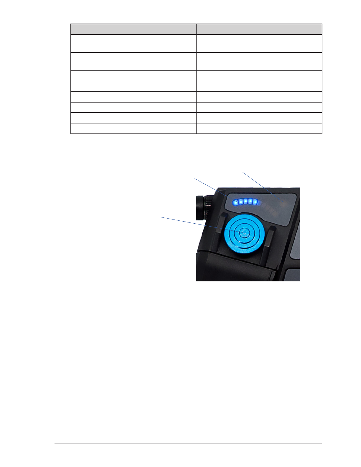
5.2.3. Joystick
1 Joystick
2 Position indicator display
3 Joystick status LED
The joystick is a control interface with a relative position encoder. Press the joystick up or
down to control the assigned axis. The joystick´s touch sensitivity and the axis speed can be
adjusted individually in the “Joystick menu” (please refer to section “6.2.3.2.3. Joystick” on
page 41 in this manual). As default, the joystick is assigned to zoom.
5.2.3.1. Position indicator display
The position indicator display consits of 10 blue single LEDs. It indicates the relative
position of the assigned axis in %. If the display is o, the motor is at one end stop of the
lens (= < 10%). If the display is fully illuminated the motor is at the other end stop of the
lens 100%. The joystick position indicator display can be illuminated individually through
the “Joystick brightness” menu. As default, the joystick is assigned to zoom.
5.2.3.2. Joystick status LED
The status LED for the joystick is a seperate LED above the position indicator display. This
gives you direct feedback of the status of the joystick axis.
2
1
3
All content © 2018, cmotion GmbH. All specications are subject to change without further notice.
http://www.cmotion.eu
page 18 of 80
LED status Meaning
o no axis assigned to joystick / joystick illu-
mination o
solid green motor ready, no warnings, limits set
green/yellow ashing calibration request
yellow ashing motor calibration
solid yellow calibration time out
solid red no motor connected
red ashing joystick locked / no motor control
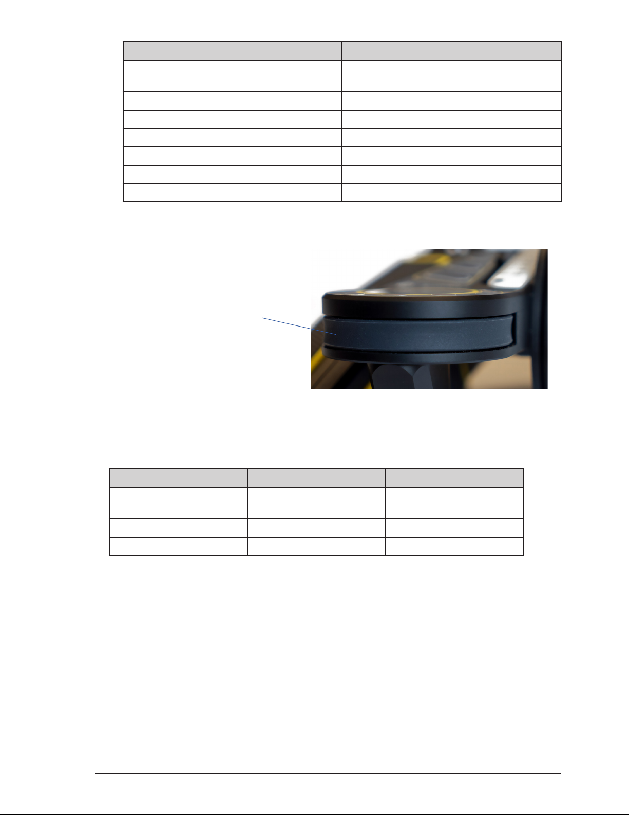
5.2.4. Thumb wheel
1 Thumb wheel
The thumb wheel is a unique control interface of the cPRO hand unit with a relative position
encoder. It allows you to navigate through all the menu pages comfortably even when wearing
gloves. It is even possible to assign the thumb wheel as a 4th axis controller (available with
Software Release Package v2.0).
NAVIGATION Thumb wheel gesture Function
in main screens scroll clockwise / scroll
counter-clockwise
scroll through horizontal
menu and display screens
in adjustment menu scroll clockwise navigate up
scroll counter-clockwise navigate down
5.2.5. Buttons / camera status LED
With the exception of the REC button, the HOME button and menu button 2 (MB2), all
buttons on the cPRO hand unit can be assigned individually. And, all buttons except the
back button (BB1) illuminate once assigned to a user function.
User button functions*:
O / Focus limits set / Iris limits set / Zoom limits set / Focus calibration / Iris calibration /
Zoom calibration / Calibration all / ZAP / Joystick speed up / Joystick speed down / Autofocus
press / Autofocus toggle / Autofocus pinpoint / System unit / Steath mode / Laser pointer /
Camera rec / Lock knob / Lock slider / Lock joystick / Lock thumb wheel
*(more user button functions available with Software Release Package v2.0)
1
All content © 2018, cmotion GmbH. All specications are subject to change without further notice.
http://www.cmotion.eu
page 19 of 80
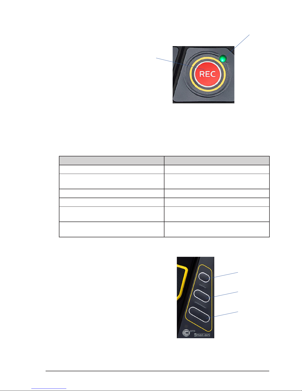
5.2.5.1. REC button and camera status LED
1 REC button
2 Camera status LED
The REC button is assigend to “Camera rec” only and cannot be changed. Anyways the
“Camera rec” function can be assigned to any other user button.
The camera status LED is next to the REC button and gives direct feedback of the camera
status.
LED status Meaning
o no camera interface is available
solid green camera interface is available / camera
ready
solid red camera is recording
red / green ashing camera is in idle mode (camera not ready)
red ashing slow remaining record time is less than ve
minutes
red ashing fast remaining record time is less than one
minute
5.2.5.2. User buttons
1 User button 1 (UB1)
2 User button 2 (UB2)
3 User button 3 (UB3)
All user buttons (UB1/UB2/UB3) in the center of the cPRO hand unit can be assigned
individually. Once assigned to a user function, each assigned button will illuminate
individually unless keypad brightness is set at 0.
1
2
1
2
3
All content © 2018, cmotion GmbH. All specications are subject to change without further notice.
http://www.cmotion.eu
page 20 of 80
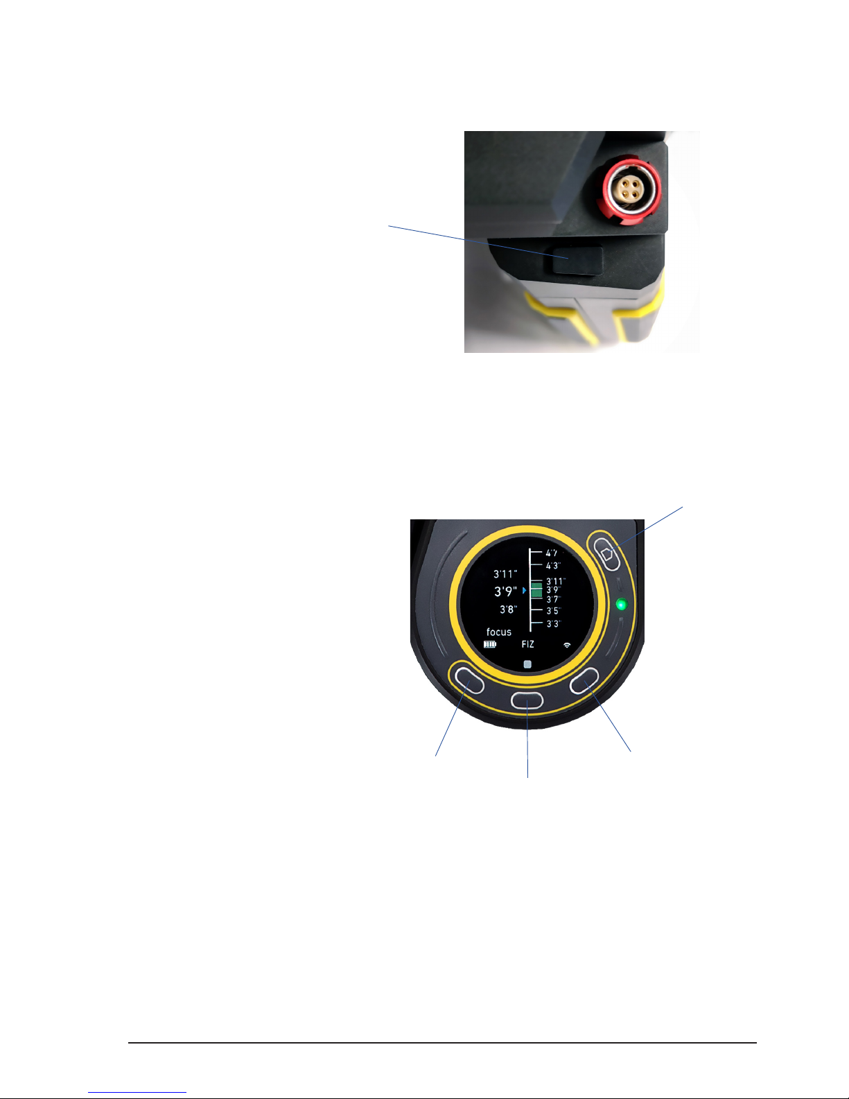
5.2.5.3. Back button
1 Back button (BB1)
The back button is located on the hand grip of the cPRO hand unit, underneath the LBUS
connector. It is not illuminated but can be assigned individually to any user function.
5.2.5.4. Menu buttons
1 Menu button 1 (MB1)
2 Menu button 2 (MB2)
3 Menu button 3 (MB3)
4 HOME Button
3 menu buttons are located around the touch screen. And, with the exception of MB2,
can be assigned to any user function while displaying one of the main screens. When
entering the adjustment menu the menu buttons will change their behaviour and show
their function on the touch display.
5.2.5.4.1. MB2 (QUICK NAV)
Menu button 2 (MB2) is permanently assigned to allow quick navigation between main
screens with multiple pages, and from specic main screens directly into the related
adjustment menu. MB2 is illuminated permanently if the keypad brightness is not set at 0.
1
1
2
3
4
Table of contents
Other cmotion Camera Accessories manuals


