CMR Electrical DPC200 User manual

home
DPC200 PRESSURE - VOLUME CONTROL
DPC200 Page 1
Copyright © 2000 CMR® C.M.RICHTER EUROPE LTD All rights reserved The information is subject to change without notice Issue GB 2 - 1 2001
CMR CONTROLS
Division of C.M.RICHTER EUROPE LTD
22 Repton Court Repton Close
Basildon Essex SS13 1LN GB
Website : http://www.cmr.co.uk
Tel +44 (0) 1268 287222
Fax +44 (0) 1268 287099
e-mail: sales@cmr.co.uk
DPC200 Controller with Type 'J' display, hand-auto and Alarms
DPM50/55 Sensor
V- F- VT- Sensors
CMR Extract Valve
Invertor 0-100Hz
P-Sensor
REMOTE CMR SENSORS
The DPC200 was designed to function with
all CMR measurement sensors for which
data sheets are available separately. The
most popular sensors are the DPM50
Pressure and the DPM55 air velocity or
volume instruments. The units are normally
built into a central control panel together with
the DPC200 s.
OTHER REMOTE CMR SENSORS
The sensors can also be mounted in the field
at any distance and the CMR P-Sensors
either in ABS or Aluminium Enclosures are
ideal for pressure control. The V-Sensors, F-
Sensors and VT-Sensors are used for air
volume control either for constant or variable
air volume applications.
CMR DAMPERS AND ACTUATORS
CMR provides a large range of dampers
either circular or rectangular with a variety of
actuators from 4 up 150 seconds rotation
speed for 0...90°. The DPC200 can control
all these actuators accurately and without
hunting. It is recommended to use CMR
dampers and actuators as the mechanical
strength and torque of the actuator is critical
when operating at very high speeds.
FAN SPEED INVERTOR CONTROL
The DPC200 is ideal to control any Fan
Speed Invertor from small to large
applications either on static pressures or fan
volumes using the CMR fan inlet ring
measuring probes. It is of great advantage
where an independent control loop is
required to provide fail safe operation. The
DPC200 can run the fan in auto or manual
mode and provides override capability for
the BMS.
The DPMs have the advantage to provide
additional alarm contacts and a separate
4...20mA signal to independent pressure
monitoring systems. Another feature is the
large LED display which indicates the
pressures or velocities on the front panel for
the operator convenience. Calibration is
also made easy as all the controls are under
the front lense of the DPM.
GENERAL
The DPC200 was designed to provide accurate air volume and
room pressure control especially in clean room environments but
over the years it has found a multitude of uses in all kinds of control
systems. The principle of the control is simple and easily adopted
by any controls engineer. It consists of one control loop with a
number of options such as auto or manual control and remote BMS
interface. The DPC200 can be connected to any CMR external
sensor, damper motor or fan speed invertor. It provides constant air
volume control in ventilation systems or accurate room pressure
control especially in pharmaceutical production and research
areas. It has an option for local and remote alarm outputs and has
BMS and Scada monitoring systems connectivity. Full calibration
certificates traceable to National Standards can be supplied to
make the CMR control system conform to validation procedures.
REMOTE MEASUREMENT SENSORS
The Controller can read in a 0...10V signal from any CMR sensor.
The sensor actual value is displayed on an LCD Display on the front
operators panel of the DPC200. The LCD Display is normally scaled
0...100% of the 0...10V but can be scaled to different engineering
units i.e. Pa, mBar, m/s etc.
AUTO CONTROL SET POINT
A set point adjustment dial is provided for the user to select an
operating set point. The dial is available either as 0...100% or
-100%...0...+100% depending on type ordered.
CONTROL OUTPUT OPEN- OFF- CLOSE OR 0...10V/4...20mA
The DPC can drive all fast acting CMR motors which have a 24VAC
synchronous motor to drive open or close. Because of the high
speeds, the controller has all built in facilities to control in all
applications without hunting.
The DPC is also available with 0...10V output normally used for fast
acting Invertor Fan Speed Controls or specialist damper actuators.
MANUAL HAND CONTROL
A Hand-Auto switch is provided. When selecting the Hand option,
the manual set point dial is made active and the user can select a
manual operating set point to drive the invertor or damper into any
position. This is ideal for commissioning or emergency actions. The
dial is scaled to 0...100% as standard.
The actual speed of the Fan Invertor i.e. 0...100% of the Hz output or
the position of the actuator i.e. 0...100% of the damper angle is
continuously monitored. This value is available as 0...10V signal to
the BMS and the LCD display.
POWER SUPPLY
The DPC200 can be supplied for various power supplies such as
24V AC, 110V AC and 230V AC.
• Ultra fine pressure or volume control
• Controls fan speed invertors and actuators
• Hand - Auto and BMS change over control
• Local or external BMS actual sensor display
• Local or external BMS position sensor display
• Internal or remote BMS set point adjustment
• Door switch control freeze with timer
• Low and High alarm thresholds and alarms
• Volt free alarm contact for remote BMS.
• Excellent repeatability
• After Sales Service is provided by CMR
• 24 month warranty
• 20 Years field application experience
For External Pressure or Volume Sensors
DPC200 CLEAN ROOM CONTROLLER
DPC200 Page 2
Copyright © 2000 CMR® C.M.RICHTER EUROPE LTD All rights reserved The information is subject to change without notice Issue GB 2 - 1 2001
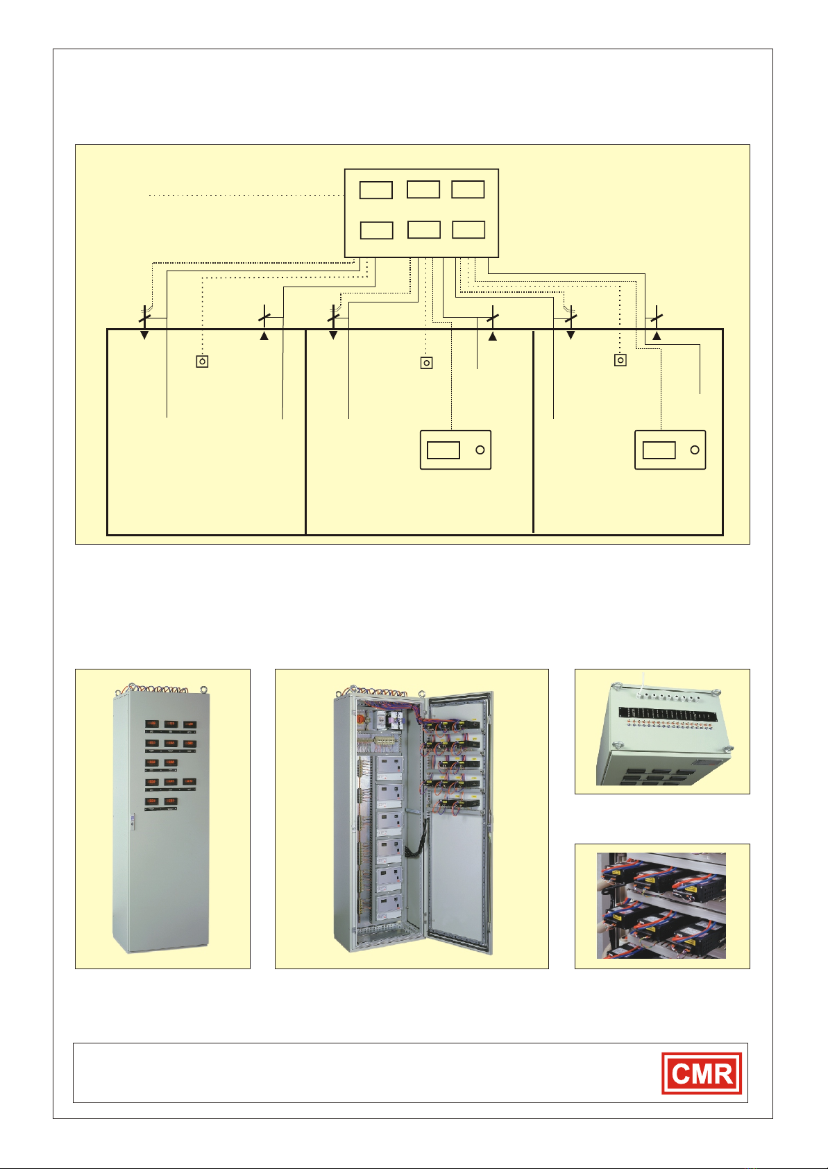
The above CMR Control Panel has three DPM55 air volume sensors
fitted into the front door. The air volume is measured at the venturi
mounted into the CMR Valve providing an accurate air volume
measurement. The DPC200 reads the air volume and controls the
constant volume supply (CVS) valves to provide constant air-change
rate into the rooms. Three DPM50 room pressure sensors are also
fitted into the front door.
CMR CONTROLS
Division of C.M.RICHTER EUROPE LTD
22 Repton Court Repton Close
Basildon Essex SS13 1LN GB
Website : http://www.cmr.co.uk
Tel +44 (0) 1268 287222
Fax +44 (0) 1268 287099
e-mail: sales@cmr.co.uk
White White
White
DPC200 CONTROL PANEL
Reference Datum
Air Probe Air ProbeAir Probe
Blue PVC Tube
30.00.15 45.0
Pa Pa Pa
ROOM 1 ROOM 2 ROOM 3
Up to 200m Distance
Up to 200m Distance
45.0
CMR remote alarm
display/mute plate
5 Core Cable 5 Core Cable
CMR remote alarm
display/mute plate
30.0
0.93
0.45 0.50
m3/s m3/s m3/s
Red-Blue
Red-Blue
Red-Blue
CVSCVS CVS
VVE VVE VVE
CONSTANT SUPPLY (CVS) AND VARIABLE VOLUME EXTRACT (VVE) CONTROL
door open
control freeze
door open
control freeze
door open
control freeze
door open
control freeze
door open
control freeze
door open
control freeze
CMR Control Panel with DPM50 and
DPM55 instruments built into the
front door for remote measurement.
Internal view of the CMR Panel. An isolator, fuses, power
supply, computer interface terminals and six DPC200
Controllers are fitted on the back plate All factory tested.
CMR panel door showing the rear of
the DPMs. Designed for easy access
during calibration in future.
TYPICAL ROOM PRESSURE AND VOLUME CONTROL PANEL FITTED WITH DPM50/55s AND DPC200s
Top of the CMR panel with all tube
nipple connections, cable glands
and identification engraving.
Each room pressure is measured against a reference datum i.e. plant
room and is controlled by driving the CMR motorised Variable Volume
Extract Valves (VVE) to the pressure set point at an adjustable speed
to provide stabile room pressure at any time. Remote display and
alarm plates are provided for the operator's safety. Door open
interlock switches can be connected to freeze the controls. When the
door is closed again a timer is provided to re-activate the controls.
TYPICAL ROOM PRESSURE CONTROL AND VOLUME TRACKING
DPC200 AIR CONTROL APPLICATIONS
DPC200 Page 3
Copyright © 2000 CMR® C.M.RICHTER EUROPE LTD All rights reserved The information is subject to change without notice Issue GB 2 - 1 2001
In most cases, the DPM instruments and DPCs are built into a central
panel located in the plant room. PVC tubing is installed up to 200m in
length to the constant volume valves and the room pressure air probe
plates. The advantage of a central panel is easy commissioning, final
calibration and validation.
The DPC200 is a standard controller which can be configured to
provide constant supply, constant extract, variable volume supply or
variable volume extract. It has the necessary interfaces to be set up as
a tracking controller which means the extract DPM gives a signal to
the supply DPC to follow and provide the same volume as the extract.
An offset can be adjusted to either have more or less extract to suit the
application.
CMR CONTROLS
Division of C.M.RICHTER EUROPE LTD
22 Repton Court Repton Close
Basildon Essex SS13 1LN GB
Website : http://www.cmr.co.uk
Tel +44 (0) 1268 287222
Fax +44 (0) 1268 287099
e-mail: sales@cmr.co.uk
TYPICAL STATIC PRESSURE AND CONSTANT VOLUME FAN SPEED AND DAMPER CONTROL APPLICATIONS
STATIC PRESSURE CONTROL
Supply Fan Speed Control Extract Fan Speed Control Extract Damper Control Supply Damper Control
1360 Pa
+-
DPC200 DPC200
-360 Pa
+-
DPC200
+-
DPC200
CONSTANT VOLUME CONTROL
Supply Volume Fan Control ExtractVolume Fan Control Extract Volume Damper Control Supply Volume Damper Control
DPC200 DPC200
+-+-
DPC200
DPC200
+-
0.45 m3/s
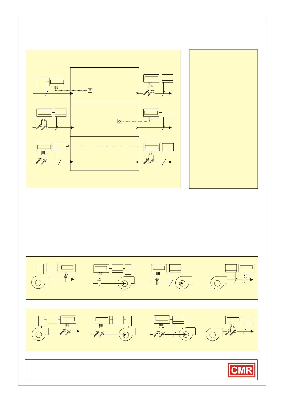
CLEAN ROOM AIR CONTROLS
ROOM A
The extract is set up as constant volume
extract (CVE) to maintain 0.45m3/s.
The supply air is set up to be variable
volume supply (VVS). The room
pressure is measured via the air probe
and the supply air is controlled to
maintain -45Pa in the room.
ROOM B
The supply air is set up to be a constant
volume supply (CVS) to maintain
0.62m3/s.
The extract is set up as variable volume
extract (VVE). The room pressure is
measured via the air probe and the
extract air is controlled to maintain
+15Pa in the room.
ROOM C
The supply is set up as constant volume
supply (CVS) and the extract is set up as
constant volume extract (CVE). The
volume can be offset by external means
i.e. BMS and both CVE or CVS can track
each other. The DPC is adjustable to
achieve either over or under pressure in
the controlled space. The schematic
shows the extract volume sets the
supply volume.
DPC200
+-
0.45 m3/s
- 45 Pa
+-
DPC200
DPC200
+-
+ 15 Pa
DPC200
+-
0.62 m3/s
DPC200
+-
0.45 m3/s
DPC200
+-
0.40 m3/s
ROOM A
ROOM B
ROOM C
AIR PROBE
AIR PROBE
VVS CVE
CVS VVE
CVECVS
-45Pa
+15Pa
It can also be set up to measure the supply air and let the extract
follow. It is recommended to use the CMR dampers and valves with
CMR actuators, as the mechanical connections and the gearboxes
have been designed for continuous high speed action all year round.
All DPCs and DPMs can be connected to remote MPCs, BMS or
Scada computers systems to read in the pressures, volumes and set
points. The DPC can also receive remote set points and be controlled
to be in automatic or manual mode. In case of computer failure, the
DPC reverts back to its default set points, a vital advantage in critical
manufacturing processes. Any CMR Sensors can be connected and
supplied with traceable calibration certificates to National Standards
and site certification can be carried out on request.
0.45 m3/s 1.12 m3/s
1360Pa
-360 Pa
+-
+-
1.21 m3/s

DPC200 DAMPER CONTROL METHODS
Damper Actuators can either be the OPEN-OFF-CLOSE or the 0-10V Type
CMR CONTROLS
Division of C.M.RICHTER EUROPE LTD
22 Repton Court Repton Close
Basildon Essex SS13 1LN GB
Website : http://www.cmr.co.uk
Tel +44 (0) 1268 287222
Fax +44 (0) 1268 287099
e-mail: sales@cmr.co.uk
Copyright © 2000 CMR® C.M.RICHTER EUROPE LTD All rights reserved The information is subject to change without notice Issue GB 2 - 1 2001
DPC200 Page 4
The room must be controlled at 15Pa positive pressure using
variable volume supply and manual constant extract. On start up,
the supply damper must be open and starts closing if the room
pressure is greater than 15Pa. The damper motor stops when a
door is opened and re-starts after a time out when closed again.
The room must be controlled at -45Pa negative pressure using
variable volume supply and manual constant extract. On start up,
the supply damper must be closed and starts opening if the room
pressure is more negative than -45Pa. The damper motor stops
when a door is opened and re-starts after a time out when closed
The room must be controlled at 1.0m3/s constant supply volume.
On start up, the supply t damper must be open and if the volume is
more than the set point the damper starts closing to achieve the
required constant volume. The controller has an adjustable set
point to vary the supply volume if required. The DPC can be linked
to an extract DPC controller if fitted to provide supply to extract
tracking.
+15 Pa
DPC
200
Constant
Volume
Extract
CVE
VVS
Variable
Volume
Supply
Positive Room Pressure
+15 Pa
-45 Pa
Constant
Volume
Extract
CVE
VVS
Variable
Volume
Supply
Negative Room Pressure
-45 Pa
1.0m3/s
Controlled
Constant
Volume
Supply
Constant Supply Volume
1.0m3/s
Constant
Volume
Extract
CVE
CVS
Mode 'A'
Mode 'C'
Mode 'E'
door switch
air Probe
door switch
air Probe
DPC
200
DPC
200
The room must be controlled at 15Pa positive pressure using
variable volume extract and manual constant supply. On start up,
the extract damper must be closed and starts opening up if the
room pressure is greater than 15Pa.The damper motor stops when
a door is opened and re-starts after a time out when closed again.
The room must be controlled at -45Pa negative pressure using
variable volume extract and manual constant supply. On start up,
the extract damper must be open and starts closing if the room
pressure is more negative than -45Pa. The damper motor stops
when a door is opened and re-starts after a time out when closed
The room must be controlled at 1.2m3/s constant extract volume.
On start up, the extract damper must be open and if the volume is
more than the set point the damper starts closing to achieve the
required constant volume. The controller has an adjustable set
point to vary the extract volume at any time. The DPC can be linked
to a supply DPC controller if fitted to provide extract to supply
tracking.
+15 Pa
Constant
Volume
Extract
CVS V VE
Variable
Volume
Extract
Positive Room Pressure
+15 Pa
- 45 Pa
Constant
Volume
Extract
CVS V VE
Variable
Volume
Extract
Negative Room Pressure
- 45 Pa
1.2m3/s
Controlled
Constant
Volume
Extract
Constant Extract Volume
CVE
1.2m3/s
Constant
Volume
Supply
CVS
Mode 'B'
Mode 'D'
Mode 'F'
TYPICAL AIR PRESSURE OR AIR VOLUME DAMPER CONTROLS USING DPC200 CONTROLLERS.
door switch
door switch
air Probe
air Probe
DPC
200
DPC
200
DPC
200

DPC200 FAN SPEED CONTROL METHODS
CMR CONTROLS
Division of C.M.RICHTER EUROPE LTD
22 Repton Court Repton Close
Basildon Essex SS13 1LN GB
Website : http://www.cmr.co.uk
Tel +44 (0) 1268 287222
Fax +44 (0) 1268 287099
e-mail: sales@cmr.co.uk
Copyright © 2000 CMR® C.M.RICHTER EUROPE LTD All rights reserved The information is subject to change without notice Issue GB 2 - 1 2001
DPC200 Page 5
The room must be controlled at 15Pa positive pressure using
variable volume supply and manual constant extract. On start up,
the supply fan must speed up and starts reducing speed if the room
pressure is greater than 15Pa. The fan speed locks when a door is
opened and re-starts after a time out when closed again.
The room must be controlled at -45Pa negative pressure using
variable volume supply and manual constant extract. On start up,
the supply fan must reduce speed and starts speeding up if the
room pressure is more negative than -45Pa. The fan speed locks
when a door is opened and re-starts after a time out when closed
The room must be controlled at 1.0m3/s constant volume supply.
On start up, the supply fan must speed up and if the volume is more
than the set point the fan speed starts reducing to achieve the
required constant volume. The controller has an adjustable set
point to vary the supply volume if required. The DPC can be linked
to the extract fan to provide supply to extract tracking.
+15 Pa
Manual
Constant
Volume
Extract
CVE
VVS
Controlled
Variable
Volume
Supply
Positive Room Pressure
+15 Pa
-45 Pa
Manual
Constant
Volume
Extract
CVE
VVS
Controlled
Variable
Volume
Supply
Negative Room Pressure
-45 Pa
1.2m3/s
Controlled
Constant
Volume
Supply
Constant Supply Volume
1.0m3/s
CVS
Mode 'G'
Mode 'J'
Mode 'L'
door switch
door switch
air Probe
air Probe
DPC
200
DPC
200
DPC
200
The room must be controlled at 15Pa positive pressure using
variable volume extract and manual constant supply. On start up,
the extract fan must reduce and starts speeding up if the room
pressure is greater than 15Pa. The fan speed locks when a door is
opened and re-starts after a time out when closed again.
The room must be controlled at -45Pa negative pressure using
variable volume extract and manual constant supply. On start up,
the extract fan must speed up and starts reducing speed if the room
pressure is more negative than -45Pa. The fan speed locks when a
door is opened and re-starts after a time out when closed again.
The room must be controlled at 1.2m3/s constant volume extract.
On start up, the extract fan must speed up and if the volume is more
than the set point the fan speed starts reducing to achieve the
required constant volume. The controller has an adjustable set
point to vary the extract if required. The DPC can be linked to the
supply fan to provide extract to supply tracking.
+15 Pa
Manual
Constant
Volume
Extract
CVS
VVE
Controlled
Variable
Volume
Extract
Positive Room Pressure
+15 Pa
- 45 Pa
Manual
Constant
Volume
Extract
CVS
VVE
Negative Room Pressure
- 45 Pa
1.2m3/s
Constant Volume Extract
CVE
1.2m3/s
Mode 'H'
Mode 'K'
Mode 'M'
TYPICAL AIR PRESSURE OR AIR VOLUME FAN SPEED CONTROL USING DPC200 CONTROLLERS.
Controlled
Variable
Volume
Extract
Controlled
Constant
Volume
Extract
CVE
door switch
door switch
air Probe
air Probe
DPC
200
DPC
200
DPC
200
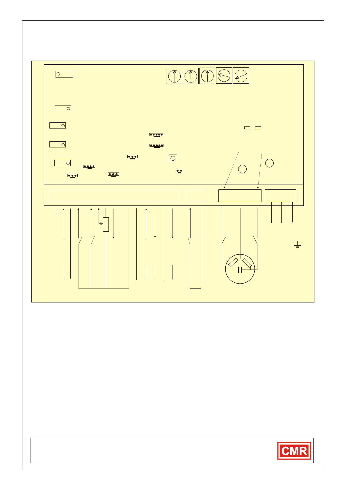
DPC200 AST-VMS/L MOTOR CONTROL
DPC200 CONTROL BOARD WITH TRIAC OUTPUT TO DRIVE SYNCHRONOUS MOTORS
CMR CONTROLS
Division of C.M.RICHTER EUROPE LTD
22 Repton Court Repton Close
Basildon Essex SS13 1LN GB
Website : http://www.cmr.co.uk
Tel +44 (0) 1268 287222
Fax +44 (0) 1268 287099
e-mail: sales@cmr.co.uk
Copyright © 2000 CMR® C.M.RICHTER EUROPE LTD All rights reserved The information is subject to change without notice Issue GB 2 - 1 2001
DPC200 Page 6
25 27 29
PE
Earth
24/ 110/ 230 VAC
0 VAC
20 22 24
1 2 3 4 5 6 7 8 9 10 11 12 13 14 15 16 17 19
J8
Power Supply
Must be ordered
to suit the voltage
Prop-
band
Timing
Sensi-
tivity
sensor
signal
Balance
DO NOT
ADJUST
unless
used as
off-set.
Scaler 2
Positioner
P16
ZERO
P15
SPAN
P10 is factory adjusted but if it was
tampered with turn P10 fully clockwise and
then 10 turns anti clockwise
Try for best results 8 - 11 turns.
To stop hunting
adjust P10 and
finger pots
Try Sensitivity
Prop Band
Timing and
look at LED's
for best results
P10
J9
J1
J2
J7
P18
P4
ZERO
P5
SPAN
Scaler 1
Remote sensor
Hand/Auto switch
Internal Sensor
Actual Set Point
Manual Set Point
Door switch
control freeze
Door delay timer
Red
LED
Green
LED
If 'on' 20 is
energised
If 'on' 24 is
energised
External Set Point
(-)(+)
0...10V DC
External Set Point
Hand/Auto Change
Potentiometer in Actuator
0...10V DC
10V DC Reference
(-) (+)
0...10V DC
(+) (-) (+)
0...10V DC
5...24V DC 150mA
External Sensor Input
Scaled Sensor Actiual Output
Power Supply for External Sensor
24VAC
0 VAC
0 VAC
Synchronous
Motor Actuator
Normally 24V AC
DPS201T
Coarse Fine
Factory setting as shown
End
switch
End
switch
LCD1
LCD2
Sensor
Position
To change direction of actuator change over the wiring motor from 20 to 24 and 24 to 20
and the feed back potentiometer from 8 to 11 and 11 to 8 and adjust Scaler 2..
COMMISSIONING DAMPER ACTUATOR MOTION
he green LED must be on and
With no pressure or volume applied to the sensor and the setpoint
set to +50% the green LED must be on and the damper must drive
to closed position on 20. If not, change over motor wires from 20 to
24 and 24 to 20 to change direction of motor. Adjust the end limit
switches in the motor to give fully closed position.
Apply pressure to (+) port of the sensor so that the signal is higher
than the set point, the red LED must be on and the damper should
drive to open position 24. Adjust the open limit switch to fully open
position. Repeat this process a few times until correct.
Control method: Damper must be open on start up.
With no pressure or volume applied to the sensor and the setpoint
set to +50% t the damper must drive to
open position on 20. If not, change over motor wires from 20 to 24
and 24 to 20 to change direction of motor. Adjust the end limit switch
in the motor to give maximum opening position.
Apply pressure to (+) port of the sensor so that the signal is higher
than the set point and the damper should drive to closed position.
The red LED and 24 should be on. Adjust the closed limit switch to
fully closed position. Repeat this process a few times until correct.
Control method : Damper must be closed on start up.
COMMISSIONING DAMPER ACTUATOR POSITION
Control method: Damper must be open on start up.
The scaler 2 is the actuator position potentiometer scaling.
The potentiometer is connected to 11 (10V) and 8 (GND) the output
wiper is connected to 7. When the damper is fully open adjust span
(P15) to 10V measured on 9. Close the damper as described on the
left. Adjust the zero (P16) to be 0V on 9.
If the damper works incorrectly change over 8 to 11 and 11 to 8 to
inverse the potentiometer function and repeat above process until
correct.
Control method: Damper must be closed on start up.
The scaler 2 is the actuator position potentiometer scaling.
The potentiometer is connected to 11 (10V) and 8 (GND) the output
wiper is connected to 7. When the damper is fully closed adjust span
(P15) to 10V measured on 9. Open the damper as described on the
left. Adjust the the zero (P16) to be 0V on 9.
If the damper works incorrectly change over 8 to 11 and 11 to 8 to
inverse the potentiometer function and repeat above process until
correct.
Scaled Position Output 0...10V
Not normally connected
see page 9
F1
F2
Main Fuse
Motor Fuse
When door is open switch is made and
the output to the motor frezes.
When door is closed switch is open.
The output starts after delay time out.
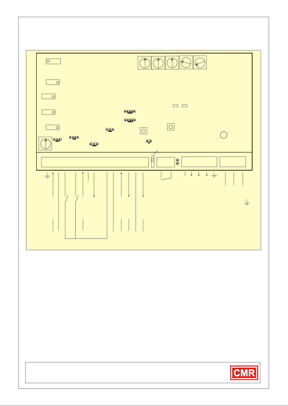
DPC200 CONTROLLER 0-10V OR 4-20mA
DPC200 CONTROL WITH 0...10V/4...20mA OUTPUT TO DRIVE FAN SPEEDS OR DAMPER MOTORS
CMR CONTROLS
Division of C.M.RICHTER EUROPE LTD
22 Repton Court Repton Close
Basildon Essex SS13 1LN GB
Website : http://www.cmr.co.uk
Tel +44 (0) 1268 287222
Fax +44 (0) 1268 287099
e-mail: sales@cmr.co.uk
Copyright © 2000 CMR® C.M.RICHTER EUROPE LTD All rights reserved The information is subject to change without notice Issue GB 2 - 1 2001
DPC200 Page 7
COMMISSIONING A
On start up the fan must speed up or the damper opens
With no pressure or volume applied to the sensor and the set point
set to +50% the green LED must be on and 0...10V drives the fan up
or damper open. If not, change over the invertor switch to normal
position to change direction of the output signal. Adjust any top end
limits on the external equipment if required. Apply a pressure or flow
to (+) port of the sensor so that the signal is higher than the set point
and the Fan should reduce speed or the damper closes. The red
LED must be on and 0V drives the fan down. Adjust any end limits on
the external equipment if required. Repeat this process a few times
until correct.
The scaler 2 is the feed back positioner scaling circuit..
The feed back voltage from the Invertor or damper motor should
preferably be 0...10V. The signal is fed into 7. If the fan is in low
speed position adjust zero (P16) to read 0V on 9. If the fan is in full
speed position adjust span (P15) to read 10V on 9. Try the controller
on manual control by changing the set point. Repeat this process a
few times until correct.
COMMISSIONING B
On start up the fan must reduce speed or the damper closes.
With no pressure or volume applied to the sensor and the set point
set to +50% the green LED must be on and 10 ... 0V drives the fan
down or closes the damper. If not, change over the invertor switch to
inverted output position to change direction of the output signal.
Adjust any top end limits on the external equipment if required.
Apply a flow to (+) port of the sensor so that the signal is higher than
the set point and the Fan should speed up. The red LED must be on
and 10V drives the fan up or the damper opens. Adjust any end limits
on the external equipment if required. Repeat this process a few
times until correct.
It is essential that the external equipment can invert the feed back
signal otherwise the DPC270 cannot function. Consult CMR in case
of difficulties.
The scaler 2 is the feed back positioner scaling circuit..
The feed back voltage from the Invertor or damper motor should
preferably be 10...0V. The signal is fed into 7. If the fan is in low
speed position adjust span (P15) to read10V on 9. If the fan is in full
speed position adjust zero (P16) to read 0V on 9. Try the controller
on manual control by changing the set point. Repeat this process a
few times until correct.
Inverted Output 10-0V
Switch down for normal and up for inverted control
Front Plate Set Points
P19
When door is open switch is made and
the control output freezes.
JP9
25 27 29
PE
Earth
24/ 110/ 230 VAC
0 VAC
1 2 3 4 5 6 7 8 9 10 11 12 13 14 15 16
Power Supply
Must be ordered
to suit the voltage
Prop-
band
Timing
Sensi-
tivity
sensor
signal
Balance
DO NOT
ADJUST
unless
used as
off-set.
P10 is factory adjusted but if it was
tampered with turn P10 fully clockwise and
then 10 turns anti clockwise
Try for best results 8 - 11 turns.
To stop hunting
adjust P10 and
finger pots
Try Sensitivity
Prop Band
Timing and
look at LED's
for best results
P10
J9
J1
J2
J7
P18
Hand/Auto switch
Internal Sensor
Door switch
control freeze
Door delay timer
External Set Point
(-)(+)
0...10V DC
External Set Point
Hand/Auto Change
10V DC Reference
(-) (+)
0...10V DC
(+) (-) (+)
0...10V DC
5...24V DC 150mA
External Sensor Input
Scaled Sensor Actiual Output
Power Supply for External Sensor
Coarse Fine
Factory setting as shown
LCD1
LCD2
Sensor
Position
Scaled Position Output 0...10V
Not normally connected
see page 9
F1 Main Fuse
DPS201V
Red
LED
Decrease
Green
LED
Increase
P20 Output Ramp Speed
J8
Scaler 2
Positioner
P16
ZERO
P15
SPAN
P4
ZERO
P5
SPAN
Scaler 1
Remote sensor
2nd Set Point
20 21 22 23 24
17 19
20...4mA
If jumper is fitted than T22 is connected to T7
Control Output
suitable for
Invertors or
Damper Motors
When door is closed switch is open.
The output starts after delay time out.
GND (-)
10...0V DC
24 VAC 50Hz 150mA
from internal
(+)
0...10V DC
(-)
External Position Feed Back
4...20mA
0...10V DC

DPC200 CONTROL BOARD FUNCTION
CMR CONTROLS
Division of C.M.RICHTER EUROPE LTD
22 Repton Court Repton Close
Basildon Essex SS13 1LN GB
Website : http://www.cmr.co.uk
Tel +44 (0) 1268 287222
Fax +44 (0) 1268 287099
e-mail: sales@cmr.co.uk
Copyright © 2000 CMR® C.M.RICHTER EUROPE LTD All rights reserved The information is subject to change without notice Issue GB 2 - 1 2001
DPC200 Page 8
THE LINK SETTINGS ARE FACTORY SET AND TESTED TO WORK WITH A DPC200 AS ORDERED
POTENTIOMETERS
P1 Sets the external sensor power
supply voltage on14 from 5 to 24VDC.
P2 Set P3 fully clockwise to have
maximum output on 11 then adjust P2
to have 10V on 11.
P3 follow P2
P4 If the Jumper on JP7 scaler1 has
been set to up position then P4 is the
span adjustment for the external
sensor coming in on 13 and out on 16.
P5 see P4. P5 is the zero adjustment
for scaler1.
P15 if Jumper on JP7 scaler2 has
been set to up position then P15 is the
span adjustment for the feed back of
the position sensor coming in on 7 and
out on 9.
P16 see P15. P16 is the adjustment for
the zero for scaler2.
LINK SETTINGS
Sensor input on 13
JP7 1- 3 2- 4 scaler 1 connected
JP7 3- 5 4- 6 scaler 1 not connected
Square Root Option
Position Sensor on 7
JP7 7- 9 8-10 scaler 2 connected
JP7 9-11 10-12 scaler 2 not connected
External Set Point on 2
Standard factory setting
JP8 3- 5 9- 11 scaler 2 not connected
Square Root and scaler2 option
If the set point must be square rooted
in case of tracking two volumes with
pressure sensors then link as follows:
If input on 13 must be square rooted
then link as follows:
JP7 1- 3 2- 4 scaler 2 connected
JP8 2- 4 square root connected
JP8 8- 9 square root connected
JP7 9-11 10-12 scaler2 not on7
JP8 1- 3 7- 9 scaler 2 connected to 2
Internal Set Point P3 connection
If a plain plate has been ordered and
no potentiometer can be connected to
the board then P3 is the internal set
point. In order to make it function link:
JP6 1-3 P3 is now internal set point
To commission P3 turn P3 fully
clockwise, measure on 10 and adjust
P2 until 10.00 V is achieved. Then turn
P3 from 0-100% = 0...10V internal set
point.
Note: if P3 is used as set point 11
cannot be used as reference 10V.Use
14 instead and adjust P1 to 10V on 14.
20 21 22 23 24
17 191 2 3 4 5 6 7 8 9 10 11 12 13 14 15 16
P10
P9
P2
P3
P5
Scaler 1
Scaler 2
Zero
P16 Zero
P4 Span
P15 Span
JP11
JP12
LCD1
LCD2
P1
J2 J1
J6 J5 J4 J3
Zero
coarse
Hand - Auto
14
Internal
set point
Prop
band
TimingSensi-
tivity
Balance
Do not
adjust
unless
used as
off set
1N4148 1N4148
J8
Manual
set point
IsolationTransformer
24VAC
or
110VAC
or
230VAC
50/60 Hz
J9
Internal
sensor
JP6
JP8
JP14
JP7
JP15
JP16
Sensor Value
Manual Value
1
1
1
1
1
1
1
1
5
5
3
3
1 3
R1 R2
Linear1
Linear2
SQR1
SQR2
scaler1
scaler2
10V scalers for 11
turn P2 fully clock
wise Adjust 10V
with P3 on 11
25 26 27 28 29
5..24V
GND
Sensor
Manual
Sensor always
5..24V
GND
Sensor
Manual
Manual always
DPC200 LINK - FRONT PLATE CONNECTORS AND POTENTIOMETER SETTINGS
2
11 12
12
2
11
F1
F2
Correct Power
Supply must be
selected at the
time of order
Main
Motor
24VAC POWER SUPPLY
The standard power supply is 24VAC on J3 with
fuse F1 (1A). With the 24VAC version the
damper motor is connected directly to the
external power supply linked under the board
toJ3 via a separate fuse F2 (1A). Any 24VAC
motor can be connected to J4 provided the
external power supply is large enough to drive
one 24VAC synchronous motor up to 1A.
110V-230VAC POWER SUPPLY
The optional power supply is 110V or 230VAC
on J3 with fuse F1 (315mA). With this version
the 24VAC is produced by the on-board
isolation transformer and a maximum of
350mA can be connected to J4. In this case the
board must be configured to internal 24VAC
supply to J4. Do not exceed the maximum
power available from the board. Consult CMR.
OPTIONAL FC201 ALARM BOARD CONNECTIONS AND SETTINGS
JP7
If the alarm board is fitted as retrofit in the field, make sure that the link JP7 is unsoldered.
Use SW1 switch settings to achieve different alarm modes and times.
30 31 32 33 34 35 36 37 38 39 40 41
High
J2
Low
Off
1 2 3 4 5 6 7 8
Alarm Setpoint
Test Points
Earth
Mute
Mute
Ground
makes R3
24VDC
NC
Common
Common
Common
Buzzer
Lo-Hi Alarm
Re-peater
Front Panel
Mute switch
Alarm connected
to Front Plate
SW1
Front Panel
Alarm Lamp
SW1
R1 R2 R3
1 3
3
1
6 On=Latching Alarm
7 On=Re-Alarm Timer set
8 On=High Alarm on Re-peater
Off=Sash Alarm Output
4 off - 5 off 0s Alarm Delay
4 off 5 on 10s Alarm Delay
4 on 5 off 30s Alarm Delay
4 on 5 on 60s Alarm Delay
1 n/a
2 n/a
3 n/a
4 Timer
5 Timer

DPC200 OPERATOR FRONT PANEL
CMR CONTROLS
Division of C.M.RICHTER EUROPE LTD
22 Repton Court Repton Close
Basildon Essex SS13 1LN GB
Website : http://www.cmr.co.uk
Tel +44 (0) 1268 287222
Fax +44 (0) 1268 287099
e-mail: sales@cmr.co.uk
Copyright © 2000 CMR® C.M.RICHTER EUROPE LTD All rights reserved The information is subject to change without notice Issue GB 2 - 2 2001
DPC200 Page 9
FRONT PANEL EXPLANATION CHOICE OF FRONT PANELS WITH OR WITHOUT ALARM
0..100%
CONTROL
SET POINT
0..100%
MANUAL
SET POINT
CONTROL
VALUE
50.0 %
CAL
OFF
ON
8
2
7
9
MANUAL
POSITION
50.0 %
AUTO
HAND
1
10
1. LCD displays the actual sensor value in %
2. Control set point in 0...100% or -100..100 %.
3. Low Alarm set point 0...100% or -100 ..100 %.
4. High Alarm set point 0...100% or -100..100 %.
5. Alarm light switches on after time out of alarm.
6. If the Mute button is switched to off position, then
the buzzer shall switch on after the time out of
any alarm. In on position, the buzzer is always
muted.
7. In auto the controller follows the sensor set point.
In hand operation the controller follows the
manual set point.
8. LCD displays manual position of the actuator or
the feed back of the invertor in %.
9. Control set point for the Manual positioner.
10. When switching the CAL to on, the control
output freezes and the sensor can be calibrated
CHOICE OF FRONT PANELS
TYPE 'A' Fully populated with alarms, hand - auto
and LCDs for actual sensor and position
feed back. The sensor range is 0...100%
suitable for positive range only.
TYPE 'B' Same as Type 'A' but sensor range is
-100%-0-+100% suitable for positive
and negative range.
TYPE 'C' Same asType 'A' but without alarm.
TYPE 'D' Same as Type 'B' but without alarm.
TYPE 'E ' Same asType 'C' but without manual
LCD and without manual set point.
TYPE 'F' Same as Type 'D' but without manual
LCD and without manual set point.
TYPE 'G' Same as Type 'A' but with digital set
point adjusters instead of dial.
TYPE 'H' Same as Type 'G' but without manual
LCD and without manual set point.
TYPE 'I' Same as Type 'H' but without alarms.
TYPE 'J' Same as Type 'G' but without alarms.
TYPE 'K' Plain plate without any controls.
Note: The layout may change . Consult CMR.
FRONT PLATE TYPE 'J' 0...100%DIGITAL TYPE 'I'
SENSOR
SET POINT
0..100%
CONTROL
VALUE
50.0 %
CAL
OFF
ON
2
7
AUTO
HAND
1
10
0...100% FRONT PLATE TYPE 'A'
-100%-0-100% FRONT PLATE TYPE 'B'
%%
100 100
0 0 100
%
CONTROL
SET POINT
100
0 %
MANUAL
SET POINT
LOW HIGH
ALARM
CONTROL
VALUE
50.0 %
CAL
OFF
ON
MUTE
OFF
8
23 4
56
7
9
0
-100%-0-100% FRONT PLATE TYPE 'D'
0...100% FRONT PLATE TYPE 'C'
-100%-0-100% FRONT PLATE TYPE 'F'
0...100% FRONT PLATE TYPE 'E'
0...100% PLATE DIGITAL TYPE 'G' 0...100% PLATE DIGITAL TYPE 'H'
MANUAL
POSITION
50.0 %
ON
AUTO
HAND
1
%%
100 100
-100 -100 100
%
CONTROL
SET POINT
100
-100 %
MANUAL
SET POINT
LOW HIGH
ALARM
CONTROL
VALUE
50.0 %
CAL
OFF
ON
MUTE
OFF
8
23 4
56
7
9
0
MANUAL
POSITION
50.0 %
ON
AUTO
HAND
1
100
%
CONTROL
SET POINT
1000 %
MANUAL
SET POINT
CONTROL
VALUE
50.0 %
CAL
OFF
ON
8
2
7
9
0
MANUAL
POSITION
50.0 %
AUTO
HAND
1
100
%
CONTROL
SET POINT
100-100 %
MANUAL
SET POINT
CONTROL
VALUE
50.0 %
CAL
OFF
ON
8
2
7
9
0
MANUAL
POSITION
50.0 %
AUTO
HAND
1
SET POINT
100-100 %
CONTROL
VALUE
50.0 %
CAL
OFF
ON
2
7
9
AUTO
HAND
1
SET POINT
1000 %
CONTROL
VALUE
50.0 %
CAL
OFF
ON
2
7
AUTO
HAND
1
%%
100 100
0 0
0..100%
CONTROL
SET POINT
0..100%
MANUAL
SET POINT
LOW HIGH
ALARM
CONTROL
VALUE
50.0 %
CAL
OFF
ON
MUTE
OFF
8
2
34
56
7
9
MANUAL
POSITION
50.0 %
ON
AUTO
HAND
1
%%
100 100
0 0
CONTROL
SET POINT
0..100%
LOW HIGH
ALARM
CONTROL
VALUE
50.0 %
CAL
OFF
ON
MUTE
OFF
2
34
56
7
ON
AUTO
HAND
1
10
10
10 10
10
10
10 10

DPC200 PRESSURE - VOLUME CONTROLLER TO BE USED WITH EXTERNAL SENSOR
DPC200 ORDER DESCRIPTION
DPC200 Page 10
Copyright © 2000 CMR® C.M.RICHTER EUROPE LTD All rights reserved The information is subject to change without notice Issue GB 2 - 1 2001
CMR CONTROLS
Division of C.M.RICHTER EUROPE LTD
22 Repton Court Repton Close
Basildon Essex SS13 1LN GB
Website : http://www.cmr.co.uk
Tel +44 (0) 1268 287222
Fax +44 (0) 1268 287099
e-mail: sales@cmr.co.uk
GENERAL
CMR manufactures a large range of DPC200 wall or panel mount
pressure or volume controllers to suit many applications. Because of
the variety of control outputs and power supplies it has been
necessary to design an easy to use selection table for anybody to
make up a DPC200 controller specification to satisfy a requirement.
You will find all specifications available with the associated ordering
Code on the DPC200 Controller Selection Table (Page 11) . In order
to select the correct part we have made up a sample selection
below:
DPC200 PART NUMBER
The DPC200 Part Number starts with the selection of the controller
type of enclosure without Lid, with Lid or with Lid and key lock.
DPC200 enclosure without Lid has the Code ’ 66A ’.
DPC200 enclosure with Lid has the Code '66B'
DPC200 enclosure with Lid and key lock has the Code '66C'
As an example, we have chosen the Code 'A'.
The Part Number starts therefore with '66A'
NEGATIVE PRESSURE RANGE
The DPC200 is always supplied without internal sensor and acts as
controller only. If a sensor is required, refer to the CMR P-Sensor,
DPM, V-Sensor, VT-Sensor and F-Sensor specification sheets.
As there is no sensor fitted the Code is always '000'.
The Part Number extends to ‘66A 000’.
POSITIVE RANGE
The DPC200 is always supplied without internal sensor and acts as
controller only. If a sensor is required, refer to the CMR P-Sensor,
DPM, V-Sensor, VT-Sensor and F-Sensor specification sheets.
As there is no sensor fitted the Code is always '000'.
The Part Number extends to ‘66A 000 000’.
OPERATOR FRONT PANEL
The operator panel is an anodized aluminium panel which has
various options as shown on page 9. The choice of plate is
expressed as Plate Type as follows:
Type 'A' has all functions and the sensor control set point is a dial
0...100%. The order Code is 'A'
Type 'B' is similar to Type 'A' except the sensor set point dial is
-100..0..+100% . This type is used , when using a sensor which has
a measurement range i.e. -100Pa - 0 - +100Pa, which means the
sensor can measure from 0Pa to(-)100Pa and from 0Pa to (+)100Pa
and the set point can be adjusted from 0 to (-)100% and 0 to
(+)100%. The Code is 'B'.
Other Types are available such as 'C' up to 'J'. see DPC200
Operator Front Panel on page 9.
In the example we have chosen Type 'A'
The Part Number extends to ’66A 000 000 A’.
POWER SUPPLY
The DPC200 can be ordered for 24VAC with Code '3', 110VAC with
Code '4' and 230VAC with Code '5'.
We have chosen 24VAC which has the Code '3'.
The Part Number extends to ’66A 000 000 A 3’.
CONTROL MODE
Page 4 and Page 5 shows various control modes. The mode
selection is important to set up the controller's output. Look at the
sketches and select the desired mode or ask CMR for assistance.
We have chosen Mode 'B' on page 4.
The Part Number extends to ’66A 000 000 A 3 B’.
CONTROL OUTPUT
The Industry Standard for Output Signals is 0...10V which has the
order Code 'A'. The Control output signal can also be inversed to
provide 10...0V. This is normally required, when a fan must be at
high speed at no pressure feed back. The Code is 'B'.See Page 5
Speed Control Methods.
The Control output for CMR damper motors as described on Page 4
Damper Control Methods is a triac output to drive synchronous
motors open-off-close. The output is generated by the isolation
transformer built into the DPC, which means the output is named
24VAC I (internal) and has the code 'C'. This means no matter what
the power supply is i.e. 24VAC, 110VAC or 230VAC by choosing
code 'C' the control output is always 24VAC (internal) but it is limited
to 350mA.
If AC X (external) Code 'D' is ordered, then the control output is the
same as the power supply i.e. 24VAC, 110VAC or 230VAC non
isolated.
It is advisable to mention what type of equipment shall be driven by
the DPC200 controller during order stage in order to make sure the
control output is capable to drive the used actuator.
We have chosen 24V ACX as control output which has the Code 'D'.
The Part Number extends to ‘66A 000 000 A 3 B D'.
SCALED UNITS
The range is printed on the product label fixed to the lid of the
controller. Normally, the range is printed in % but other ranges can
be selected under this order code. If and LCD or LED is required
then the set point dials are always in %.The set point dials and
manual LCD are always in % and cannot be scaled unless a special
factory order is made. The 3 1/2 digit sensor LCD is factory scaled
to suit the front operator plate ordered. If the front plate is Type 'A'
than the sensor LCD is calibrated as 0-100.0%. If the front plate
Type 'B' is selected than the sensor LCD is scaled to -100% to
+100% over the range. The order code for % scaling is '1'.
The sensor LCD can be ordered calibrated in other engineering
units and full details of range must be specified during order stage.
Pa (Pascals) has the Code '2' , mBar has the Code '3'.
m/s has the Code '4', m3/s has the Code '5'
In the example we have chosen the Code '1' .
The Part Number extends to ‘66A 000 000 A 3 B D 1'
DECIMAL PLACES
If no LCD is fitted then this is N/A (not applicable).
The 3 1/2 digit LCD can only display 1999 or 199.9 or 19.99 or
1.999 all depending on the decimal place setting.
No decimal place can be set to Code 'A' which displays 000
Code 'B' displays 00.0, Code 'C' displays 0.00
Code 'D' displays .000
We have chosen the standard setting 00.0 with Code 'B'.
The Part Number extends to ‘66A 000 000 A 3 B D 1 B'
ALARM FUNCTION
The DPC200 can be supplied with an alarm threshold output board
as described on page 8. The board has a low/high alarm relay and a
buzzer relay. A low and high threshold set point adjuster is on the
front of the control panel. If the sensor signal is below or above the
threshold, a timer can be programmed to switch on the alarm and
buzzer relay. The buzzer can be muted. A repeater relay is available
for remote BMS input. If the alarm board is not required the Code
shall be '0' for 'NO'. If the alarm board is required, the order Code is
'1' for 'AL'
In the example we have chosen Code '0'.
The Part Number extends to ‘66A 000 000 A 3 B D 1 B 0'
FINAL PART NUMBER to order is ' 66A000000A3BD1B0'.

Make up your own DPC200 Pressure Volume Controller selection below using the empty cells
HOW TO ORDER
CMR CONTROLS
Division of C.M.RICHTER EUROPE LTD
22 Repton Court Repton Close
Basildon Essex SS13 1LN GB
Website : http://www.cmr.co.uk
Tel +44 (0) 1268 287222
Fax +44 (0) 1268 287099
e-mail: sales@cmr.co.uk
DPC200 Page 11
Copyright © 2000 CMR® C.M.RICHTER EUROPE LTD All rights reserved The information is subject to change without notice Issue GB 2 - 1 2001
DPC200 ORDER SELECTION TABLE
EXAMPLE PART NUMBER SELECTION ( The code after the ( = ) sign is used i.e. No Lid = 66A )
EXAMPLE
A wall mount pressure controller is required of the type DPC200
The DPC200 shall have a Lid with a key lock
The DPC200 will be used with an external sensor type DPM50
The negative pressure range must be -100Pa
The positive pressure range must be +100Pa
The front plate must have two dial set points for hand/auto with two LCDs and Alarms
The power supply must be 24V AC
The control output must be 0...10V to drive a fan speed invertor on the Supply
The scaled units must be in %
The indication must be 100.0% with one decimal place
An Alarm contact must be provided
The part Number for this DPC200 is 66C 000 000 B 3 G A 1 B 1
The control mode should be VVS to control positive pressure with a fan ( Mode 'G')
Call CMR for assistance at any time
66A
DPC200
Part No.
000
Negative
Range
000
Positive
Range
A
Front
Plate
No Lid = 66A
With Lid = 66B
With Key =66C
N/A = 000 T = A
T = B
T = C
T = D
T = E
T = F
T = G
T = H
T = I
T = J
T = K
3
Power
Supply
24 VAC = 3
110 VAC = 4
230 VAC = 5
B
Decimal
Places
0
Alarm
fitted
N/A = N
000 = A
00.0 = B
0.00 = C
.000 = D
NO =0
YES =1
D
Control
output
0...10V = A
10...0V = B
24VAC I = C
AC X = D
1
Scaled
Units
% = 1
Pa = 2
mBar = 3
m/s = 4
m3/s = 5
N/A = 000
B
Control
Mode
N/A = 0
Mode = A
Mode = B
Mode = C
Mode = D
Mode = E
Mode = F
Mode = G
Mode = H
Mode = I
Mode = J
Mode = K
Mode = L
Mode = M
The selection Table has been prepared to make ordering easy. Each
Column contains a number of different options which are available
and a Part Number can be established by yourself depending on
your specific requirements.
The Example Part Number 66A 000 000 A 3 B D 1 B 0 which is
printed above the Selection Table can be identified as being a
DPC200 Pressure - Volume Controller.
The controller has no Lid and is suitable for an external CMR
sensor. The Negative and Positive Range is not applicable. The
front plate is fully populated Type 'A' with 0...100% sensor set point
dial. The power supply is 24VAC, the control mode is Type B driving
an extract damper motor in positive pressure. The control output is
24V ACX . The LCD is scaled to 0...100.0% with one decimal place.
No alarm is required.
THE SELECTION TABLE IS FOR A DPC200 CONTROLLER WITH EXTERNAL SENSOR
DPC200 TECHNICAL SPECIFICATION
CMR CONTROLS
Division of C.M.RICHTER EUROPE LTD
22 Repton Court Repton Close
Basildon Essex SS13 1LN GB
Website : http://www.cmr.co.uk
Tel +44 (0) 1268 287222
Fax +44 (0) 1268 287099
e-mail: sales@cmr.co.uk
DPC200 Page 12
Copyright © 2000 CMR® C.M.RICHTER EUROPE LTD All rights reserved The information is subject to change without notice Issue GB 2 - 1 2001
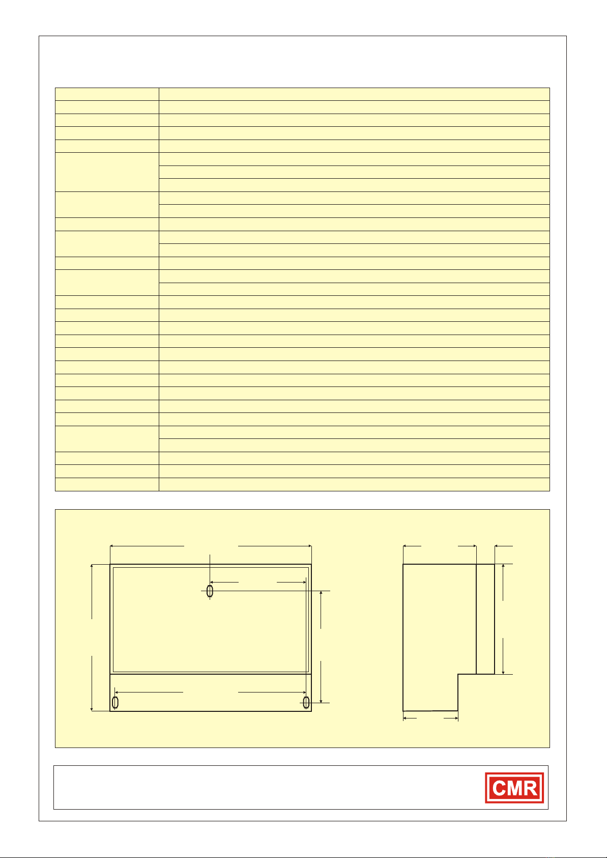
ENCLOSURE DIMENSIONS
Measurement Range
Control Range Sensor
Control Range Feed Back
Set Point Range
Scaler1 and 2 Range
AC Power Supplies
AC Control Output
Volt Output Signal
Set point Signal
Feed BackSignal
Sensor Signal
Proportional Band
Timing
Sensitivity
Operating-Storage Temp.
Alarm Relay Low/High
Low/high Alarm Threshold
Buzzer Relay
Repeater Relay
Alarm Timers
Relay Latching
Weight
Electrical Connections
Enclosure
Cable Glands
Conformity
Calibration Certificate
See Order Selection Table of the external CMR sensor to be used
The control range is 0...10V or 0-100% of the CMR sensor range. Input is on Terminal 13.
Any range +/- 0...10V input = +/-0...10V output. Scaler1 input T13 - out T16. Scaler 2 input T7 - out T9
24 VAC 50/60Hz Fuse 1.0 A Wickmann
110VAC 50/60Hz Fuse 315 mA Wickmann
230VAC 50/60Hz Fuse 315 mA Wickmann
24 VAC I (internal power from isolation transformer) max 350mA (Fused 1A Wickmann)
24VAC (1A), 110VAC (200mA), 230VAC (100mA) output bridged directly to Input Terminals. Fused
0-10V (0...100%) or 10...0V (100%...0%) switchable (
0...10V (0...100% of range)
0...10V (0...100% of range)
0...10V (0...100% of range)
0...30% of range
0...4 seconds adjustable
0... 10% of sensor range
Operating Temperature 10...70 °C - Storage Temperature -20 to 85
24VDC ( 1A) non inductive - single pole change over.
Adjustable 0...10V (0...100% of range)
24VDC (1A) non inductive - single pole on-off. Works on same threshold as high/low alarm.
24VDC (1A) non inductive - single pole on-off.
Switch selectable 0s - 10s - 30s - 60s.
Switch selectable - Latching or auto-reset.
1.5 kg
5 way power, 5 way control output, 2 and 3 way control board. All Plugs with Screw Connections.
ABS Plastic without perspex Lid IP44
ABS Plastic with perspex Lid with or without key lock Protection Class IP65
4 x PG13 and 1 x PG11 entries.
EN61326-1 EMC EN61010-1 SAFETY
Can be supplied with Certificate traceable to National Standards depending on external sensor used.
The control range is 0...10V or 0-100% of the position of the CMR actuator or the speed input on T7.
The set point range is 0...10V or 0-100% of the position of set point potentiometer or external input on T2
RL = 5kOhm min.) 4...20mA or 20...4mA
°C
240mm
198mm
145mm
185mm
125mm
95mm 25mm
70mm
99mm
Three point Wall Mount
Table of contents


