Samson EB LTR 43 Service manual

LEUSCH GmbH Industriearmaturen · Ziegeleistraße 10 · 41472 Neuss
Phone: +49 2131 7699-0 · Fax: +49 2131 7699-129
E-Mail: sales-leusch-de@samsongroup.com · Internet: www.leusch.de
MOUNTING AND
OPERATING INSTRUCTIONS
EB|LTR|43
Translation of the original manual
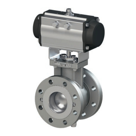
Control and shut-off valve type LTR|43 in the standard version
to combine with actuators
May 2023 edition

EB|LTR|43_EN
May 2023 edition
Subject to technical changes
Note regarding this installation and operating manual
This Installation and Operating Manual (EB) provides guidance
for safe assembly and operation.
The notes and instructions in this EB are binding when handling
SAMSON LEUSCH devices. The figures and illustrations in this EB
are examples and must therefore be considered as such.
ÖFor safe and correct use, read this EB carefully prior to use
and keep it for later reference.
ÖIn the case of questions that go beyond the scope of this
Installation and Operating Manual (EB), please contact the
nearest SAMSON office.
ÖThis manual only applies to the butterfly valve itself, the
respective additional manual applies for the mounted
actuator.
Definition of signal words
Hazardous situations that lead to death or serious injuries
Situations that can lead to death or serious injuries
Property damage and malfunctions
Additional information
Recommended action
DANGER
WARNING
NOTE
Info
Tip

EB|LTR|43_EN
May 2023 edition
Subject to technical changes
Content
Content
1 Safety instructions and safety measures 1-1
1.1 Notes regarding possible severe personnel injury 1-2
1.2 Notes regarding possible personnel injury 1-3
1.3 Notes regarding possible property damage 1-4
1.4 Warning notes on the device 1-4
2 Markings on the device 2-1
2.1 Control and shut-off valve type plate 2-1
2.2 Actuator type plate 2-1
2.3 Material markings 2-1
3 Design and principle of operation 3-1
3.1 Variants 3-2
3.2 Additional optional components on the valve 3-2
3.3 Control-related additional equipment 3-3
3.4 Technical data 3-3
4 Shipment and on-site transport 4-1
4.1 Accepting delivery 4-1
4.2 Unpacking the valve 4-1
4.3 Transporting and lifting the valve 4-1
4.3.1 Transporting the valve 4-1
4.3.2 Lifting the valve 4-1
4.4 Storing the valve 4-2
5 Installation 5-1
5.1 Installation conditions 5-1
5.2 Preparing for assembly 5-2
5.3 Assembling the butterfly valve 5-2
5.3.1 Assembling the butterfly valve and actuator 5-2
5.3.2 Installing the actuator in the pipe 5-3
5.4 Checking the assembled actuator 5-4
5.4.1 Pressure and leak test 5-5
5.4.2 Checking the rotary movement 5-6
5.4.3 Checking the fail-safe position 5-6
6 Start-up 6-1
7 Operation 7-1
7.1 Working in automatic mode 7-1
7.2 Working in manual mode 7-1
7.3 Working with the manual gear 7-1
8 Malfunction 8-1
8.1 Detecting and rectifying errors 8-1
8.2 Carrying out emergency measures 8-1

EB|LTR|43_EN
May 2023 edition
Subject to technical changes
Content
9 Servicing 9-1
9.1 Periodic tests 9-2
9.2 Preparing maintenance work 9-2
9.3 Maintenance work 9-2
9.3.1 Maintenance work on the attachments 9-2
9.3.2 Maintenance work on the actuator 9-2
9.3.3 Maintenance work on the butterfly valve in an installed condition 9-2
9.3.4 Maintenance work on the butterfly valve in a removed condition 9-5
9.4 Assembling and commissioning the actuator after maintenance work 9-5
9.5 Design of the sealing system 9-5
9.5.1 Butterfly valve LTR43-2 and LTR43-9.2 9-5
9.5.2 Butterfly valve LTR43-3 9-5
9.5.3 Butterfly valve LTR43-4 and LTR43-9.4 9-6
9.5.4 Butterfly valve LTR43-9.9 9-6
10 Decommissioning 10-1
11 Removal 11-1
11.1 Removing the butterfly valve with an assembled actuator from the pipe 11-1
11.2 Disassembling the actuator 11-2
12 Repairs 12-1
12.1 Sending devices to SAMSON LEUSCH 12-1
13 Disposal 13-1
14 Certificates 14-1
4 Annex 15-1
15.1 Tightening torques, lubricant and tools 15-1
15.1.1 Tightening torques 15-1
15.1.2 Lubricant 15-3
15.1.3 Tools 15-3
15.2 Service 15-3
15.3 Spare parts 15-3
15.3.1 Series LTR43-2, LTR43-9.2 15-4
15.3.2 Series LTR43-3 15-5
15.3.3 Series LTR43-4, LTR43-9.4 15-6
15.3.4 Series LTR43-9 15-7

1-1
EB|LTR|43_EN
May 2023 edition
Subject to technical changes
Safety instructions and safety measures
1 Safety instructions and safety measures
Intended use
The SAMSON LEUSCH control and shut-off butterfly valve type
LTR 43 is designed for use in combination with an actuator for
the regulation of the volume flow, pressure and temperature of
fluid, gaseous or vaporous media.
−The butterfly valve and its drive are designed for precisely
defined conditions (e.g. operating pressure, utilised medium,
temperature).
Therefore the operator must make sure that the butterfly valve
is only used when the conditions of use comply with the de-
sign criteria defined in the order.
If the operator would like to use the butterfly valve in other
applications or environments, they must contact SAMSON
LEUSCH.
−SAMSON LEUSCH shall not be held liable for damage that
result from non-compliance with the intended use, as well as
for damage that results from external forces or external influ-
ences.
−Limits of use, areas of use and possible uses can be found in
the technical data and on the type plate.
Reasonably foreseeable misuse
The butterfly valve is not suited for the following areas of use:
−Use outside of the technical data and the limits defined by the
design.
−Use outside of the limited defined by the attachments installed
on the butterfly valve.
Furthermore, the following activities are considered unintended
use:
−Use of third-party spare parts
−Performance of maintenance and repair work that is not de-
scribed
Qualification of operating personnel
The butterfly valve may only be installed in observance of the
recognised rules of technology, commissioned, serviced and re-
paired by specialist personnel.
−Specialist personnel in terms of this installation and operating
manual are persons who, on the basis of their vocational ed-
ucation, knowledge and experience and knowledge of the
relevant standards, are capable of evaluating the assigned
tasks and identifying possible hazards.
−In the case of valves with an explosion-protection version,
personnel must have been trained or instructed or be author-
ised to work on explosion-protected devices in plants at risk
of explosion.
Personal protective equipment
SAMSON LEUSCH recommends obtaining information regarding
the hazards resulting from the medium in use, for example using
the GESTIS substance database.
Depending on the medium that is used and/or the respective ac-
tivity, the following protective equipment, among others, may be
necessary:
−Protective garments, protective gloves and eye protection
when using hot, cold, aggressive and/or corrosive media
−Hearing protection when working in the vicinity of the butter-
fly valve
−Industrial safety helmet
−Safety harness, if there is a danger of falling (e.g. if working
unsecured at a height)
−Safety shoes, e.g. with protection against static discharge
−Request additional protective equipment from the plant oper-
ator.
Changes and other modifications
Changes, conversions and other modifications to the valve are
not authorised by SAMSON LEUSCH. They are made at your
own risk and can lead to safety risks, for example, that cause the
valve to no longer fulfil the prerequisites required for its use.
Protective devices
If the butterfly valve switches to a defined fail-safe position when
the pneumatic energy fails, it depends on the utilised butterfly
valve, see the corresponding actuator documentation. In the case
of combinations of a butterfly valve with single-acting actuators,
the butterfly valve automatically switches to a certain fail-safe po-
sition in case of a pneumatic energy failure, see Chapter 3. The
fail-safe position corresponds to the effective direction and is in-
dicated on the type plate.
Warning of residual risks
To prevent personal injury or property damage, the operator and
operating personnel must use suitable measures to prevent the
hazards that can result from the flow medium and operating
pressure as well as the signal pressure and moving parts.
−Therefore, the operator and operating personnel must ob-
serve all the hazard information, warning information and
information in this installation and operating manual.
−Hazards that result from the specific work conditions at the
area of butterfly valve use must be determined in an individu-
al risk assessment and made avoidable by corresponding in-
structions from the operator.
Obligation of the operator to exercise diligence
The operator is responsible for proper operation as well as com-
pliance with the safety regulations.
−The operator is responsible for providing operating personnel
with this installation and operating manual as well as the ap-
plicable documents and to provide instructions on proper op-
eration.
−Furthermore, the operator must ensure that operating person-
nel and third parties are not endangered.
−The operator is responsible that the limit values for the valve
defined in the technical data are not undershot or exceeded.

1-2 EB|LTR|43_EN
May 2023 edition
Subject to technical changes
Safety instructions and safety measures
−The start-up and shut-down processes are a part of the
operating process and as such, are not a part of these
installation and operating instructions. SAMSON LEUSCH
cannot make a statement about these processes, as the
operational details (e.g. differential pressures and
temperatures) differ individually and are only known to the
operator.
Obligation of operating personnel to exercise diligence
Operating personnel must be familiar with this installation and
operating manual and the applicable documents and comply
with the indicated hazard information, warning information and
other information. Furthermore, operating personnel must be
familiar with the applicable regulations concerning occupational
safety and accident prevention and observe them.
Applicable standards and directives
The valve fulfils the requirements of the following European
Directives:
−2014/68/EU Pressure Equipment Directive
−2006/42/EC Machinery Directive
−2014/35/EU Low Voltage Directive
−2014/30/EC Electromagnetic Compatibility
−2014/34/EU Equipment and protective systems intended for
use in potentially explosive atmospheres
In the case of valves provided with a CE marking, the Declaration
of Conformity provides information about the conformity
assessment procedure that was used, see Chapter 14.
Non-electrical valves do not have their own potential ignition
sources pursuant to the ignition hazard assessment in compliance
with EN ISO 80079-36, even in the case of seldom occurring
operational failures, and therefore are not subject to Directive
2014/34/EU.
ÖFor the connection to the equipotential bonding system,
observe Paragraph 6.4 of EN60079-14, VDE0165-1.
−NACE
As regards the use or application of materials according to
NACE MR0175 / ISO15156 as well as NACE MR0103
(materials in an environment containing H2S) the designation
of the standard in the material or test certificates does not
indicate suitability for use of the butterfly valve.
This depends additionally on the operating and
environmental parameters, to which generally only the plant
operator has access. Therefore the suitability for use of such
butterfly valves must always be checked by the plant
manufacturer/operator.
−SIL
The suitability for use of butterfly valves in (SIL) protective
circuits must be documented in separate agreements.
The below requirements are described in standards (e.g.
VDI2180, EN61508, EN61511) and in the applicable
SAMSON Group Manual (Functional safety for control
valves, rotary plug valves, ball valves and control butterfly
valves; WA236).
−Oxygen
Butterfly valve types LTR43-9.2, LTR43-9.4 and LTR43-9.9
are suitable for use in applications in which the oxygen
content of the operating media is greater than or equal to
35% (Vol.). All parts coming into contact with the medium are
cleaned oil and grease free and the butterfly valve is
protected by means of a specific protective packaging
against dirt and environmental influences.
All maintenance and repair work must be carried out in an
oil and grease-free environment (clean room).
The utilised tools as well as personal equipment must comply
with the cleanliness requirements.
The required cleanliness of the butterfly valve must be
ensured through suitable measures prior to reinstallation.
For butterfly valves to be used in oxygen applications, when
ordering spare parts, it must be specifically indicated that
they are for “OXYGEN USE” and the corresponding
measures must be observed.
Applicable documents
The following general and order-related documents apply in
addition to this installation and operating manual:
−EB (Installation and operating manual) for the installed
actuator
−EB for attachments (positioner, solenoid valve etc.)
−MI-LTR 43-2-SR, MI-LTR 43-3-SR, MI-LTR 43-4-SR or MI-LTR
43-9.9 SR spare seat/seal ring (applies only for the supply of
seal or rep kits)
−Data sheet TLW20010
−Technical data sheet LW-10006 Torque SB (STD)
−Technical data sheet LW-10007 Torque SB TA Luft
−Technical data sheet LW-10017 Torque DE HP
−Technical data sheet LW-10018 Risk assessment of residu-
al hazards resulting from valves with
an actuator when used as intended
−Manual WA236
−Copy of the order-related type plate
−Order-related dimensional drawing (if agreed)
1.1 Notes regarding possible severe
personnel injury
The following list indicates only generally-applicable information.
The respective chapters can contain hazard information that, due
to context, is provided in addition or is formulated slightly
differently.
Danger due to falling of suspended loads!
ÖDo not stand under suspended loads.
ÖSecure the transport paths.
DANGER

1-3
EB|LTR|43_EN
May 2023 edition
Subject to technical changes
Safety instructions and safety measures
Risk of bursting due to pressurised devices and components!
Butterfly valves and pipes are pressure equipment that can burst
if handled improperly. Projecting, flying components, fragments
and released pressurised medium can cause injuries or even
death.
ÖObserve the maximum permissible pressure the butterfly
valves and plant.
ÖEmpty the medium from the concerned plant parts and
butterfly valve.
Danger due to escaping medium as a result of unsuitable
flange seals
Leaks caused by unsuitable flange seals can cause operating
medium to escape. Flange leaks can cause fatal injury to
personnel and damage the environment.
ÖUse suitable flange seals.
ÖRequest special dimensions from SAMSON LEUSCH.
1.2 Notes regarding possible personnel injury
The following list indicates only generally-applicable warning in-
formation. The respective chapters can contain warning informa-
tion that, due to context, is provided in addition or is formulated
slightly differently.
Danger of burning due to hot or cold components and pipes!
Butterfly valves and pipes can become very hot or very cold
during operation and cause burns upon contact.
ÖLet the components and pipes cool down or warm up
ÖWear protective garments and protective gloves.
Hearing damage and deafness due to a high sound level!
Noise emissions depend on the version of the valves, the plant
equipment as well as the utilised medium. During operation,
medium-related noise emissions may be generated depending on
the plant conditions. In addition, there may be a short-term high
sound pressure level when a pneumatic actuator or pneumatic
attachment is suddenly ventilated without noise-reducing
elements. Both can damage hearing.
ÖWear hearing protection when working in the vicinity of the
actuator.
Danger of injury due to incorrect lifting without lifting
equipment!
When lifting the valve without lifting equipment, injuries may oc-
cur, especially in the torso area, depending on the weight of the
valve.
ÖObserve the occupational health and safety regulations ap-
plicable at the installation site.
Overturning of the lifting equipment and damage to the load
lifting equipment by exceeding the lifting capacity!
ÖOnly use approved lifting equipment and load lifting equip-
ment whose lifting capacity corresponds at least to the weight
of the valve and the packaging if applicable.
DANGER
WARNING
Danger of crushing due to moving parts!
The butterfly valve contains moving parts (e.g. shaft and wedge-
lock-washer) that can lead to crushing if reaching into it.
ÖDuring operation, do not reach into the bracket between the
butterfly valve and the actuator.
ÖBefore working on the valve, interrupt and lock the pneumatic
energy and the control signal.
ÖDo not allow the jamming of objects in the bracket to hinder
the rotation of the shaft.
ÖIn the case of a blocked shaft, contact SAMSON LEUSCH
through the nearest SAMSON office.
Danger of injury due to escaping exhaust air!
During operation, when regulating or when opening and closing
the butterfly valve, exhaust air can escape, for example from the
actuator.
ÖInstall the valve such that the actuator does not ventilate at
eye level.
ÖUse suitable silencers and plugs.
ÖWear eye protection when working in the vicinity of the
actuator.
Danger of injury due to preloaded springs!
Valves that are equipped with preloaded actuator springs are un-
der mechanical tension. The marking on the actuator type plate
indicates whether a spring return is available and the fail-safe
position. The marking on the type plates is described in the in-
struction manuals for the actuators.
ÖRelease the compression from the preloaded springs before
working on the actuator, see the corresponding actuator
documentation.
Danger of injury due to moving parts with spring-loaded
actuators
Spring-loaded actuators may only be pressurised when installed
in the pipe and not to perform work on the valve outside of the
pipe. There is risk of fatal injury if the pneumatic energy
suddenly fails and the valve disc moves automatically to the fail-
safe position by means of spring force.
For devices that have a spring-loaded actuator with a “fail open”
fail-safe position, the control and shut-off valve must be installed
in the open position, for example by removing the pipe.
The sealing surfaces may not be damaged during this operation.
Danger of injury due to static charge
ÖIf there is a risk of static charge of the butterfly valve, the op-
erator must ensure, to avoid it, that a suitable ground con-
nection is installed in the provided position.
Danger of injury due to residual medium in the butterfly valve!
When working on the butterfly valve, residual medium can
escape and, depending on the medium properties, cause injuries
(e.g. scalding, chemical burns).
ÖIf possible, empty the medium from the concerned plant parts
and control and shut-off valve.
ÖWear protective garments, protective gloves and eye protec-
tion.
WARNING

1-4 EB|LTR|43_EN
May 2023 edition
Subject to technical changes
Safety instructions and safety measures
Danger of injury due to pressurised components and escaping
medium!
ÖDo not loosen pressurised components.
Danger of injury due to incorrect operation, use or installation
caused by illegible information on the butterfly valve!
Over time, imprints or impressions on the valve can soil the
adhesives and signs or make them illegible for other reasons so
that dangers are not recognised and necessary operational
messages cannot be followed. Danger of injury can occur.
ÖKeep all relevant markings on the device legible at all times.
ÖDamaged, missing or faulty signs or adhesives must be
replaced immediately.
Functional impairment of the butterfly valve due to oil leaking
from the hand pump!
ÖObserve the agreed and documented actuator/valve
alignment.
Dangers due to use of the butterfly valve as an end fitting!
During normal operation, in particular with gaseous, hot and/or
hazardous media, spraying medium can cause hazards.
ÖA blind flange must be assembled on the free connecting
pieces or the butterfly valve must be secured against
unauthorised actuation.
ÖIf a butterfly valve is used as an end fitting in a pressurised
line is opened, this may only be done with extreme caution
so that the escaping medium does not cause any damage.
1.3 Notes regarding possible property
damage
Damage to the butterfly valve due to contamination (e.g. solid
particles) in the pipes!
The plant operator is responsible for cleaning the pipes in the
plant.
ÖRinse the pipes prior to commissioning.
Damage to the butterfly valve due to unsuitable medium
properties!
The butterfly valve is designed for a medium with certain
properties.
ÖOnly use a medium that corresponds to the design criteria.
Damage to the butterfly valve and leakage due to excessively
high or low tightening torques!
The butterfly valve components must be tightened with specific
torques. Excessively tightened components are subject to
increased wear. Insufficiently tightened components can cause
leakage.
ÖComply with the specified tightening torques, see Chapter
“15.1.1 Tightening torques”
WARNING
NOTE
Damage to the butterfly valve due to unsuitable tools!
Unsuitable tools can damage the valve.
ÖSuitable commercially available tools are needed to work on
the butterfly valve, see Chapter “15.1.3 Tools”.
Damage to the butterfly valve due to unsuitable lubricants!
The functionality of the butterfly valve is ensured only by using a
certain lubricant. Unsuitable lubricants can corrode and damage
the surface.
ÖThe butterfly valve material requires suitable lubricants, see
Chapter “15.1.2 Lubricants”.
Medium contamination due to unsuitable lubricants and
contaminated tools and components!
ÖIf required, for example for oxygen applications, keep the
butterfly valve and utilised tools free from solvents and
greases.
ÖOnly use suitable lubricant, see Chapter “15.1.2 Lubricant”
1.4 Warning notes on the device
Warning of moving parts.
Figure|1-1: Example of the warning information
Figure|1-2: Position on the valve
There is a risk of crushing due to the rotation of the shaft,
especially during fast rotation movements, when reaching into
the bracket as long as the pneumatic energy is connected to the
actuator, see LW 10018, Paragraph 1.3.7.
NOTE

2-1
EB|LTR|43_EN
May 2023 edition
Subject to technical changes
Markings on the device
2 Markings on the device
2.1 Control and shut-off valve type plate
The butterfly valves are marked with a metal type plate that is
fastened to the butterfly valve or, if required, in another suitable
location of the valve (e.g. extension, bridge).
Conformity with the Pressure Equipment Directive is confirmed
when the type plate bears the CE symbol with the ID number of
the notified body.
The plate provides the following information:
Figure|2-1: Sample type plate
Figure|2-2: Type plate positions
Table|2-1: Meaning of the positions on the type plate
Pos. Meaning of the marking position
1Butterfly valve type
2Nominal size (DN or NPS)
3Nominal pressure level (PN or CL)
4Order number
5Permissible pressure (PS)
6Permissible maximum temperature (TSmax.)
7Maximum permissible differential pressure on the shut-off
trim (P shut-off trim)
8Permissible minimum temperature (TSmin)
9Year and month of manufacture (Date)
10 Fluid group
11 Test point no. if available (Tag no.)
The current type plates are attached to the final documentation
for each order.
The preferable pressure force direction is marked by a direction
arrow that is integrated in the butterfly valve body or is fastened
as a metal label on the body in a suitable position. Further infor-
mation can be provided on additional metal labels.
2.2 Actuator type plate
See the corresponding documentation.
2.3 Material markings
The material markings for bodies and wedge-lock-washers are
cast into or stamped onto the respective components.

2-2 EB|LTR|43_EN
May 2023 edition
Subject to technical changes
Markings on the device

3-1
EB|LTR|43_EN
May 2023 edition
Subject to technical changes
Design and principle of operation
3 Design and principle of operation
Figure|3-1: Sectional view LTR 43
Table|3-1: Parts list
Pos. Designation Pos. Designation
1 Body 17 Bracket
2 Disc 18 Coupling
3 Seal ring 39 Packing
4 Seat A1 Centre console actuator
6 Shaft A2 Spring cylinder actuator
7 Cover A3 Pneumatic cylinder actuator
8 Gland
The LTR43 is a triple-eccentric control and shut-off butterfly
valve. It is preferably combined with pneumatic actuators in the
“rack and pinion” or “scotch-yoke” version, or can also be com-
bined with electric or hydraulic actuators as well as manual
gears.
The designed butterfly valve is available in different series for al-
most all applications and specifications for the control and shut-
off of fluids.
The series differ in the structure of the sealing system. The follow-
ing paragraph provides an example in order to explain the func-
tionality of the valve. In the case of a special design or in combi-
nation with a different auxiliary energy, the functionality may dif-
fer slightly.
The butterfly valve body (1) either contains an installed replacea-
ble seat (4) or it is integrated fixed in the body (1a). The respec-
tive seal ring (3) that is fastened to a disc (2) is connected with
the actuator via a shaft (6). The actuator itself is fixed to the valve
body by means of a bracket (17).
Adjusting the signal pressure that acts on the drive pistons (A3)
changes the position of the wedge-lock-washer with respect to
the seat, and therefore the flow rate. The springs (A2) installed in
pneumatic actuators move the wedge-lock-washer with the seal
ring into the respective fail-safe position if the pneumatic energy
fails. The seal between the body and the shaft is guaranteed by
the packing rings (39) pressed by a stuffing box (8).

3-2 EB|LTR|43_EN
May 2023 edition
Subject to technical changes
Design and principle of operation
The butterfly valve reaches its maximum tightness when it is oper-
ated according to the preferable pressure force direction (FTC)
when installed in the pipe system. The preferable pressure force
direction is indicated by an arrow on the side of the body.
Fail-safe positions
If the butterfly valve switches to a defined fail-safe position when
the pneumatic energy fails, it depends on the utilised butterfly
valve, see the corresponding actuator documentation.
The position of the wedge-lock-washer is indicated by two red
dots just above the stuffing box. When the butterfly valve is
closed, the imaginary connection axis is the red marks at a right
angle to the flow direction. When the actuator shaft rotates clock-
wise, the butterfly valve closes (clockwise to close).
Figure|3-2: Position indicator
Actuator closed by springs (FS)
Upon reduction of the signal pressure or failure of the pneumatic
energy, the springs move the actuator shaft clockwise and close
the butterfly valve.
The butterfly valve opens when the signal pressure increases, act-
ing against the force of the springs.
Actuator opened by springs (FÖ)
Upon reduction of the signal pressure or failure of the pneumatic
energy, the springs move the actuator shaft counterclockwise and
open the butterfly valve.
The butterfly valve closes when the signal pressure increases, act-
ing against the force of the springs.
3.1 Variants
For very high or very low temperatures, the butterfly valve can be
provided with a body extension and, for example, insulated with
a cold-box cover.
Various variants and special designs, such as a heating jacket
body, sealing gas connections, exterior bearing points, oxygen
versions, TA-Luft seals, etc. are available upon request.
3.2 Additional optional components on the
valve
Body extension
For operating or design temperatures below -60°C (-76°F) or
above 350°C (662°F), the valves are equipped standard with a
body extension (insulation part), see Chapter “5.2 Preparing for
assembly”.
Grip protection
In the case of conditions of use that require a high level of safety
(e.g. if the valve is freely accessible to untrained specialist per-
sonnel), grip protection must be provided to exclude the risk of
crushing due to moving parts (actuator shaft). The decision
whether to use grip protection is the responsibility of the plant
operator and depends on the risk potential of the individual
plants and their respective conditions.
Noise reduction
Trims with flow dividers can be used to reduce noise emissions.
Fixed assembly plates on the actuator for control accessories.
For optimal accessibility and maintenance, the actuator accesso-
ries can be fit on a central plate as the operator level, depending
on the application.
Weather protection equipment
To protect the valve function against the risk of pitting due to the
entry of foreign material (e.g. sand) between the stuffing box
and the shaft, additional cover plates can be attached to the
bracket upon customer request.
To protect the actuator accessory (e.g. solenoid valve, positioner)
against the sun, rain and other environmental influences, addi-
tional protective devices can be attached upon customer request.
Fire-resistant insulation
Upon customer request, the fire resistance of the valve with re-
spect to the installation environment can be increased by means
of individually customised fire protection equipment.
Danger of burns due to heated components!
Additional optional components can become very hot during
operation and cause burns upon contact.
ÖLet components and pipes cool down.
ÖWear protective garments and protective gloves.
WARNING

3-3
EB|LTR|43_EN
May 2023 edition
Subject to technical changes
Design and principle of operation
3.3 Control-related additional equipment
For valves such as rotary actuators, the following accessories are
available, for example, either individually or in combinations:
−Positioner
−Limit switch
−Solenoid valves
−Filter - reducing station
−Jacket heater
Other additional equipment is possible according to
specifications on request.
3.4 Technical data
The type plates of the butterfly valve and actuator provide
information about the butterfly valve version, see Chapter 2.1
and the actuator documentation.
Conformity
The butterfly valve type LTR43 complies with the essential
international standards, and is in particular both CE and EAC
compliant.
Temperature range
Depending on the version, the butterfly valve is designed for a
temperature range from –196 to +550°C. The temperature
range can be expanded using adapted material as well as an
insulation and body extension.
Leakage class
The following leakage classes are available upon agreement and
according to customer specifications:
−DINEN12266 Part 1 - Testing of metallic valves / ISO5208
[Leakage class A – G)
−ANSIFCI70-2 Control Valve Seat Leakage /
DINEN60534-4 (Leakage class I-VI)
−Others upon agreement
Noise emissions
SAMSON LEUSCH cannot make a general statement about noise
emission. Noise emissions depend on the version of the butterfly
valve, the plant equipment as well as the utilised medium.
Dimensions and weights
The dimensions and weights can be found on the technical data
sheet TLW20010 or on the order-related dimensions sheet of
the valve.

3-4 EB|LTR|43_EN
May 2023 edition
Subject to technical changes
Design and principle of operation

4-1
EB|LTR|43_EN
May 2023 edition
Subject to technical changes
Shipment and on-site transport
4 Shipment and on-site transport
The work described in this chapter may only be performed by
specialist personnel qualified to perform the corresponding task.
4.1 Accepting delivery
Perform the following steps after receiving the goods:
1. Check the scope of supply. Compare the data on the butterfly
valve type plate with the delivery note. For details about the
type plate, see Chapter “2 Markings on the device”.
2. Check the supply for transport damage. Report transport
damage through the nearest SAMSON office to SAMSON
LEUSCH and the transport company, see the delivery note.
3. Select suitable lifting equipment and load handling devices
according to the weight and dimensions of the valve to be
transported and lifted, see the transport documentation and
Chapter “3.4 Technical data”.
4.2 Unpacking the valve
Observe the following procedures:
ÖUnpack the valve directly before lifting for installation into the
pipe.
ÖCheck the valve for damage.
ÖUse suitable transport equipment for on-site transport.
ÖOnly remove the protective caps on the butterfly valve inlet
and outlet directly before installation into the pipe. They pro-
tect the butterfly valve against damage by preventing the en-
trance of foreign material.
ÖDispose of the packaging according to local regulations.
4.3 Transporting and lifting the valve
Danger due to falling of suspended loads!
ÖDo not stand under suspended loads.
ÖSecure the transport paths
Overturning of the lifting equipment and damage to the load
lifting equipment by exceeding the lifting capacity!
ÖOnly use approved lifting equipment and load lifting equip-
ment whose lifting capacity corresponds at least to the weight
of the valve and the packaging if applicable.
Danger of injury due to tipping of the valve!
ÖObserve the centre of gravity of the valve.
ÖSecure the valve against tipping and twisting.
DANGER
WARNING
Danger of injury due to incorrect lifting without lifting equip-
ment!
When lifting the valve without lifting equipment, injuries may oc-
cur, especially in the torso area, depending on the weight of the
valve.
ÖObserve the occupational health and safety regulations ap-
plicable at the installation site.
Damage to the valve due to improper fastening of the sling!
The lifting eye/eyebolts on the actuators are used only for actua-
tor assembling and disassembling as well as for lifting the actua-
tor without the butterfly valve. These fastening points are not in-
tended for lifting the complete valve.
ÖWhen lifting the valve, make sure that the entire load is car-
ried by the sling that is fastened to the butterfly valve body.
ÖDo not fasten the load-bearing sling to the actuator, hand
wheel or other components.
ÖObserve the conditions for lifting, see Chapter 4.3.2.
ÖDo not use the control air lines, accessories or other compo-
nents with safety functions for suspension or damage them.
4.3.1 Transporting the valve
The transport notes from the packaging (e.g. wooden box) must
be followed. The valve can be transported using lifting equipment
such as a crane or a forklift.
ÖComply with the transport conditions.
Transport conditions
ÖProtect the valve against external influences, such as impacts.
ÖDo not damage the corrosion protection (paint, surface coat-
ing). Report any damage immediately and remedy it after
consultation.
ÖProtect the pipes and any attachments from damage.
ÖProtect the valve against moisture and dirt.
ÖWhen the valve is in the standard version, the permissible
transport temperature is from –20 to +65°C.
4.3.2 Lifting the valve
When installing the valve in the pipe, suitable lifting equipment
should be used, such as a crane or a forklift. Use suitable tested
slings and suitable fastening to make sure that the surfaces and
contact surfaces are not damaged, and that no other damage
occurs to the valve (e.g. actuator accessories, piping, sealing ele-
ments).
WARNING
NOTE

4-2 EB|LTR|43_EN
May 2023 edition
Subject to technical changes
Shipment and on-site transport
Conditions for lifting
ÖUse a hook with a safety clamp as the suspension element,
see Figure 4-1, so that the sling cannot slip off the hook
during lifting and transport.
ÖSecure the sling against shifting and slipping off.
ÖFasten the sling such that it can be removed again after
installation in the pipe.
ÖAvoid swinging and tipping the valve. Pay attention to the
centre of gravity!
ÖIn the case of interruptions in work, do not leave the lifting
equipment suspended in the air for a long period of time.
Danger due to incorrect lifting and transport!
The lifting points for the lifting slings shown on the schematic
drawing serve as examples for most valve variants. On site the
conditions for lifting and transporting the butterfly valve can
change however.
ÖThe operator makes sure that the butterfly valve is lifted and
transported safely.
Figure|4-1: Sample lifting points for butterfly valves
WARNING
Figure|4-2: Sample lifting points for valve
Version: Horizontal alignment
1. Use suitable tested slings and suitable fastening to lift the
valve using suitable lifting equipment.
2. Lift the valve carefully. Check if the load lifting equipment
holds.
3. Move the valve at a constant speed to the installation site.
4. Install the valve in the pipe, see chapter “5 Installation”.
5. Remove the lifting slings after successful installation.
Upon request, SAMSON LEUSCH can provide comprehensive
transport and lifting instructions. Contact SAMSON LEUSCH
through the nearest SAMSON office.
4.4 Storing the valve
Damage to the valve due to improper storage!
ÖComply with the storage conditions.
ÖAvoid long storage periods.
ÖIn the case of deviating storage conditions and long storage,
contact SAMSON LEUSCH through the nearest SAMSON of-
fice.
SAMSON LEUSCH recommends checking the valve and the stor-
age conditions regularly during a longer storage period.
Info
NOTE
Info

4-3
EB|LTR|43_EN
May 2023 edition
Subject to technical changes
Shipment and on-site transport
Storage conditions
ÖProtect the valve in its original packaging in a covered
location in a clean and dry environment against external
influences, such as impacts.
ÖSecure the valve in the storage position against slipping or
tipping over.
ÖDo not damage the corrosion protection (paint, surface
coating). Remedy any damage immediately.
ÖProtect the valve against moisture and dirt and store at a
relative humidity of <75%. Prevent condensation in damp
rooms. Use a desiccant or heater.
ÖMake sure that the surrounding area is free of acids or other
corrosive and aggressive media.
ÖThe permissible storage temperature for valves is from –20to
+65°C.
ÖNo components may be placed on the valve.
Special storage conditions for elastomer
Example of elastomer: Actuator seals
ÖTo maintain the shape and avoid the formation of cracks, do
not suspend or bend elastomers.
ÖSAMSON LEUSCH recommends a storage temperature of
15°C for elastomers.
ÖStore elastomers separately from lubricants, chemicals,
solutions and fuels.

4-4 EB|LTR|43_EN
May 2023 edition
Subject to technical changes
Shipment and on-site transport

5-1
EB|LTR|43_EN
May 2023 edition
Subject to technical changes
Installation
5 Installation
The work described in this chapter may only be performed by
specialist personnel qualified to perform the corresponding task.
Observe chapter 4.3 for transport to the installation site.
5.1 Installation conditions
Operator level
The operator level for the actuator is the front view on all operat-
ing elements of the actuator from the perspective of operating
personnel.
The plant operator must make sure that operating personnel can
carry out all work after the butterfly valve is installed safely and
can access it easily from the operator level.
Pipe routing
Q Flow
a Entry length
b Run-out length
Figure|5-1: Entry and run-out lengths
Table|5-1: Entry and run-out lengths
Medium
state Butterfly valve conditions Installa-
tion
length a
Run-out
length b
Gaseous Ma ≤0.3 2 4
0.3 ≤Ma ≤0.7 2 10
Vaporous
Ma ≤0.3 1) 24
0.3 ≤Ma ≤0.7 1) 210
Wet steam
(Condensation percentage >5%) 220
Fluid
Cavitation free / w < 10 m/s 2 4
Sound cavitation / w ≤3 m/s 2 4
Sound cavitation / 3 < w < 5 m/s 2 10
Critical cavitation / w ≤3 m/s 2 10
Critical cavitation / 3 < w < 5 m/s 2 20
Flashing -220
Multi-phase -1020
1) no wet steam
The entry and run-out lengths depend on various variables and
process conditions and are provided as a recommendation, see
Table 5-1.
If the lengths recommended by SAMSON LEUSCH are
significantly undershot, contact SAMSON LEUSCH.
The guidelines applicable on site apply for the installation of the
butterfly valve in the pipe.
Install the butterfly valve so there is low vibration and no
mechanical tension, use a support if necessary. Observe the
sections “Installation orientation” and “Support and mounting” in
this chapter.
Install the actuator so there is enough space to replace the
actuator and butterfly valve as well as to perform maintenance
and repair work.
Installation position
The butterfly valves of the series LTR43 are designed such that it
is possible to position the actuator/butterfly valve horizontally or
vertically, whereby the standard version is vertical. The agreed
and documented installation location must be observed. If it must
be adjusted contact SAMSON LEUSCH through the nearest
SAMSON office.
Functional impairment of the actuator due to oil leaking from
the hand pump in case of an incorrect installation position!
ÖObserve the agreed and documented actuator and butterfly
valve alignment.
Support and mounting
The plant manufacturer is responsible for the selection and
implementation of a suitable support or mounting for the installed
actuator as well as the pipe.
Attachments
When connecting the attachments, make sure that they can be
operated from the operator level safely and with easy access.
Venting
Vents are screwed into the exhaust air connections of pneumatic
and electropneumatic devices to ensure that the generated
exhaust air can be released to the outside (protection against
overpressure in the device). Furthermore, vents allow the intake
of air (protection against underpressure in the device).
ÖVentilation must be oriented such that operating personnel is
not endangered. The operator must evaluate the hazard due
to noise and prevent it using suitable measures.
WARNING

5-2 EB|LTR|43_EN
May 2023 edition
Subject to technical changes
Installation
5.2 Preparing for assembly
Danger due to escaping medium resulting from unsuitable
flange seals!
Leaks caused by unsuitable flange seals can cause operating me-
dium to escape. Flange leaks can cause fatal injury to personnel
and damage the environment.
ÖThe butterfly valves of series LTR43-2 and LTR43-9.9 have
special dimensions, if applicable. It is indicated in the order
confirmation or the dimension sheet if special dimensions are
required.
ÖSpecial dimensions can be requested from SAMSON
LEUSCH. Contact SAMSON LEUSCH through the nearest
SAMSON office.
Danger of injury due to moving parts with spring-loaded
actuators!
Spring-loaded actuators may only be pressurised when installed
in the pipe and not to perform work on the butterfly valve outside
of the pipe. There is risk of fatal injury if the pneumatic energy
suddenly fails and the valve disc moves automatically to the fail-
safe position by means of spring force.
ÖInstall butterfly valves that have a spring-loaded actuator with
the “fail open” fail-safe position in the open position. Remove
the pipe if necessary.
ÖDo not damage the sealing surface.
Employees or third parties may not be endangered.
Any applicable legal regulations of the country of destination
must also be observed.
Actuators of series LTR|43-2, LTR|43-4 and LTR|43-9 have an
interrupted flange sealing surface on one side.
For sealing surfaces according to EN1092-1B1 and B2 as well
as ASMEB16.5 RF and ASMEB16.47 RF, it must be ensured that
the flat seals are suitable according to EN1514-1 and/or
ASMEB16.21.
Other seals.
For other seals, such as spiral or grooved gaskets, the standard-
ised dimensions may not be suitable.
ÖContact SAMSON LEUSCH for suitable special dimensions.
ÖUpon request, SAMSON LEUSCH can supply these seals.
Damage to the butterfly valve due to incorrect insulation!
Insulate butterfly valves with a body extension with medium tem-
peratures below -60°C or above 350°C only up to the maxi-
mum permissible height.
ÖIn the case of high temperature applications, insulate only the
lowest third of the insulation part.
ÖIn the case of low temperature applications, insulate only the
lowest two thirds of the entire length.
ÖIn the case of cold-box applications, insulate the cold-box
cover up to the lower edge. If the insulation part is insulated
at an impermissibly high level, it can lose its function!
DANGER
NOTE
The plant operator is responsible for cleaning the pipes in the
plant.
Ensure the following conditions prior to assembly:
−The actuator is clean.
−The actuator and all attachments inclusive of the pipes are
not damaged.
−The data on the type plate (type, nominal size, material,
nominal pressure and temperature range) matches the plant
conditions and conditions of use. For details about the type
plate, see Chapter “2 Markings on the device”.
−Additional optional components are installed or prepared to
the point as required prior to the assembly of the actuator,
see Chapter “3.2 Additional optional components on the
actuator”.
−Sufficient installation space is available.
−The pipe connections must be aligned plane-parallel, flush
and tension-free.
−Measures for avoiding contact with hazardous media were
found.
−All welding requirements have been met.
Perform the following preparation steps for assembly:
−Get the material and tools ready that are required for
assembly.
−If the butterfly valve and actuator are already assembled to-
gether, check the screw connections for the correct tightening
torques, see Chapter “15.1.1 Tightening torques” or LW-
10017, Annex 15.2. Components can loosen up during
transport.
5.3 Assembling the butterfly valve
The tasks are listed below that are necessary for assembly and
prior to the commissioning of the butterfly valve.
Make sure before assembly that all necessary preparations are
made, see Chapter 5.2.
5.3.1 Assembling the butterfly valve and
actuator
The SAMSON LEUSCH actuators are delivered in working order.
In individual cases, the actuator and butterfly valve are delivered
separately and must be assembled.
The tasks are listed below that are necessary for assembly and
prior to the commissioning of the actuator.
Info
Table of contents
Other Samson Control Unit manuals

Samson
Samson BR14b User manual

Samson
Samson 763 Owner's manual

Samson
Samson 3271 Service manual

Samson
Samson 2405 Series Service manual

Samson
Samson 3281 Service manual

Samson
Samson 3251 Service manual

Samson
Samson EB8048-2 Service manual

Samson
Samson 3969 Service manual

Samson
Samson Valve Series Service manual

Samson
Samson 3354 Service manual

Samson
Samson 41-73 Series Service manual

Samson
Samson EB 01a Service manual

Samson
Samson TROVIS I/O User manual

Samson
Samson BR 26l User manual

Samson
Samson BR 20a Service manual

Samson
Samson 2335 Service manual

Samson
Samson 42-36 E Service manual

Samson
Samson 41-23 Series Service manual

Samson
Samson 3244 Service manual

Samson
Samson 2333 series Service manual