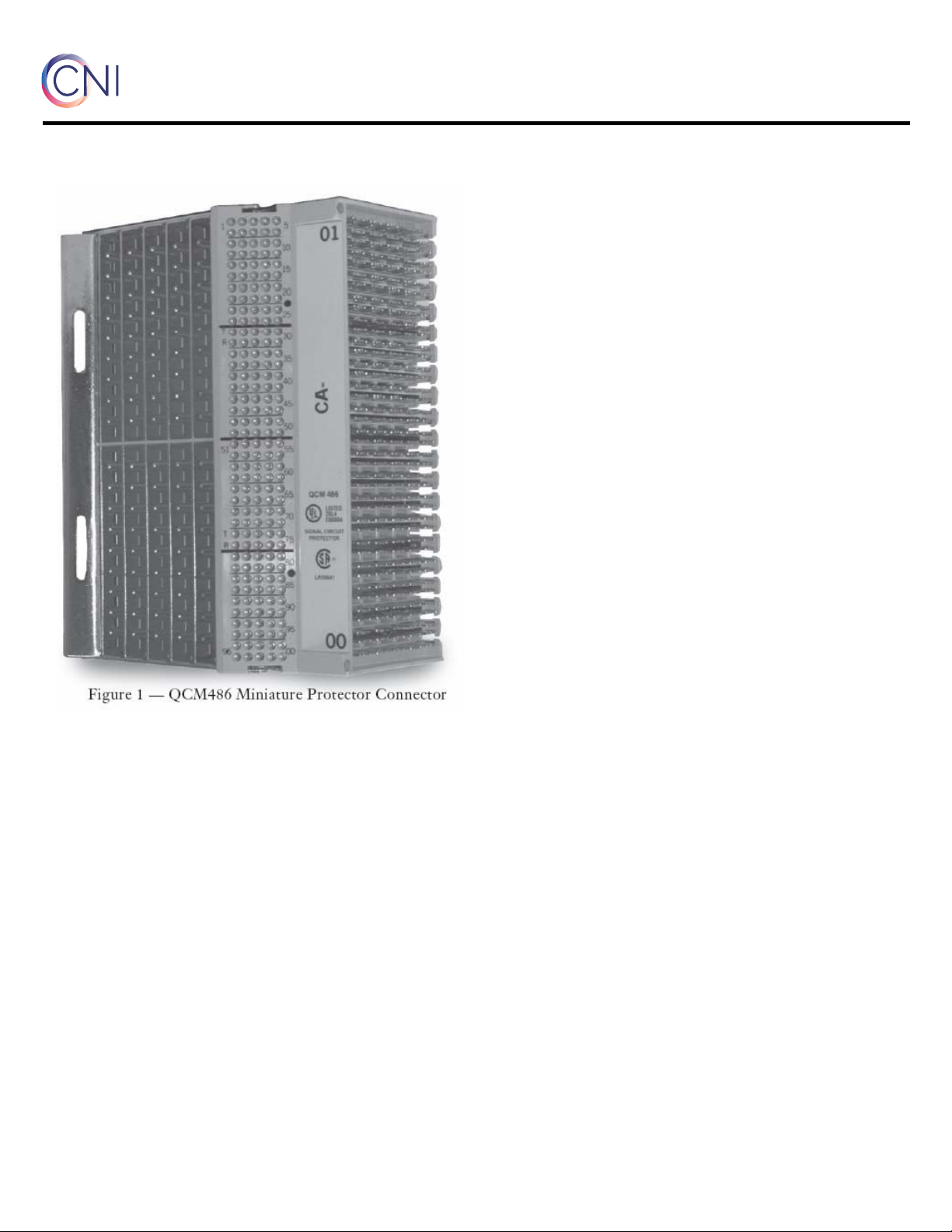
QCM486 Miniature Protector Connector (MPC)
- 2 –
comtestnetworks.com
2.4 The MPC is available stubless or equipped
with a 100-pair (top or bottom entry) stub.
Available stub lengths are 9.1, 15.2, or 30.5 mm
(30, 50 or 100 ft.) with 22 or 24-gauge
conductors. The dimensions and weights of the
MPC are shown in Table 1.
3. Precautions
3.1 The MPC is shipped in protective
packing with protector modules installed in the
detent position. Observe the following
precautions when storing, handling and
installing the unit:
•Store in a dry location. Do not leave on
loading docks or locations exposed to
weather or where temperatures are higher
than +45°C (+113°F).
•If the MPC has been exposed to
temperatures below -30°C ( - 22°F), allow
to warm to room temperature before
installing to avoid damage to cable stub.
•When unpacking, open the top of the
container marked THIS SURFACE UP AT
ALL TIMES.
•Do not remove protective packing material
around the MPC until the stub cable has
been placed through the cable vault
entrance, and the MPC is ready to be
mounted on the distributing frame.
•Do not bend the stub cable to a radius of
less than 150 mm (6 in.).
•To avoid damage to the MPC from rolling
ladders on the conventional MDF, the
ladder guard rail projection must be 650
mm (25.5 in.).
•Compact DSPF/PDF clearances for rolling
ladder and the MPC is approximately 51
mm (2 in.).
NOTE:
If this measurement is not met, contact
the Central Office Engineering Group for correction
prior to mounting MPC units.
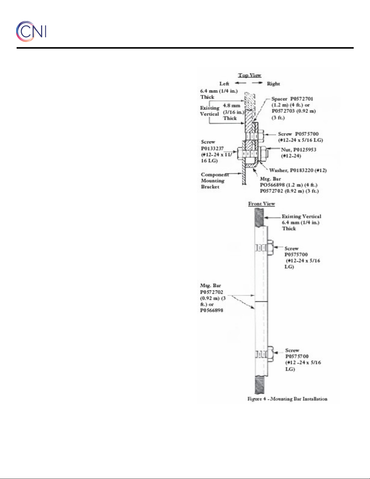
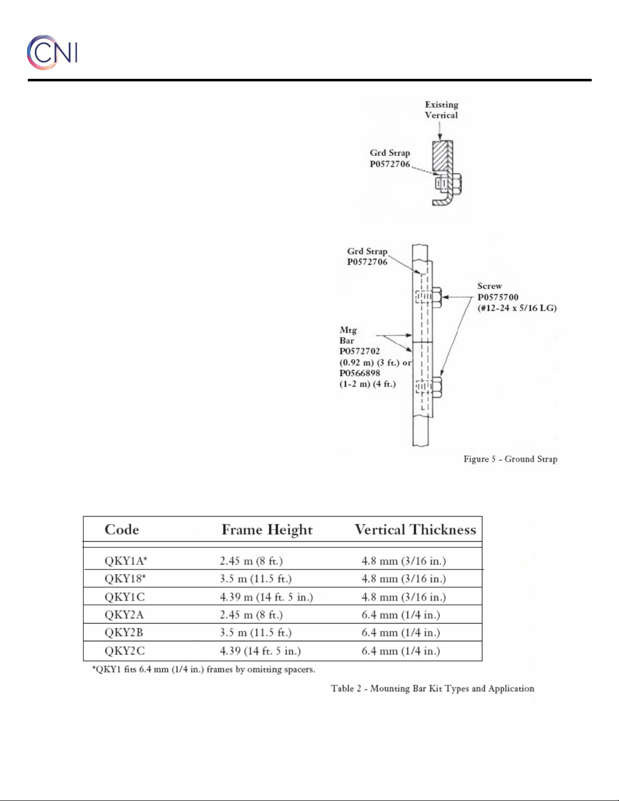
3.2 Where distributing frame verticals are not
drilled to fit MPC 140 mm (5.5 in.) mounting
centers, replace verticals, drill as required, or
install a mounting bar kit.
3.3 The following precautions are included
per requirement of the Underwriters
Laboratories Inc.®:
•National Electrical Code Requirements:
The installation of this product, including
any field-installed components, shall meet
all applicable federal, state, and local laws
and regulations and, if unrestricted, comply
with articles 800, 820 and all other
appropriate requirements of the National
Electrical Code, ANSI/NFPA 70.
•Only products marked “for indoor or
outdoor use” or “for outdoor use” are
suitable for outdoor use. Products without
this marking are not suitable for outdoor use
and are implied to be suitable for indoor use
only.
•The use of a fuse link for each and every
line is recommended when connecting any
equipment to the telephone circuit. For
typical applications, a one-foot or longer
length fuse link of at least two wire sizes
smaller than the typical wire gauge in use
within the circuit is recommended.
•It is recommended that any components
added to this product be both listed for the
purpose and compatible.
•Risk of electric shock — Protector is not to
be used without the arrester assembly
installed.