manuals.online logo
Brands
  1. Home
  2. •
  3. Brands
  4. •
  5. Wenglor
  6. •
  7. Accessories
  8. •
  9. Wenglor TK55PA7 User manual

Wenglor TK55PA7 User manual

DE
|EN
|FR
DE
wenglor sensoric GmbH
wenglor Straße 3
88069 Tettnang
(+49 (0)7542 5399-0
info@wenglor.com
Weitere wenglor-Kontakte finden Sie unter:
For further wenglor contacts go to:
Autres contacts wenglor sous :
www.wenglor.com
Änderungen vorbehalten
Right of modifications reserved
Modifications réservées
26.06.2017
Maßangaben in mm/All dimensions in mm/Mesures en mm
= Sendediode/Transmitter diode / Diode émettrice
= Empfangsdiode/Receiver diode/Diode réceptrice
Schraube/Screw/Vis M3 = 1 Nm
SAP NR. 84308
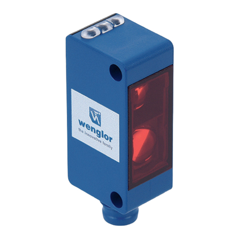
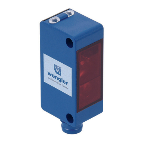
Reflextaster
Reflex Sensor
Capteur réflex
BETRIEBSANLEITUNG
OPERATING INSTRUCTIONS
NOTICE D’INSTRUCTIONS
TK55PA7
Reflextaster
Reflex Sensor
Capteur réflex
Anschlussbilder
Connection Diagrams
Schémas de raccordement
Bedienfeld
Control Panel
Panneau
+ Versorgungsspannung „+“
Supply Voltage “+”
Tension d’alimentation «+»
− Versorgungsspannung „0 V“
Supply Voltage “0 V”
Tension d’alimentation «0 V»
A Schaltausgang/Schließer (NO)
Switching output (NO)
Sortie de commutation/
Fermeture (NO)
Schaltausgang/Öffner (NC)
Switching output (NC)
Sortie de commutation/
Ouverture (NC)
05 = Schaltabstandseinsteller
Switching Distance Adjuster
Réglage de la distance
30 = Schaltzustandsanzeige/Verschmutzungsmeldung
Switching Status/Contamination Warning
Signalisation de commutation/Signalisation de l’encrassement
Bestimmungsgemäße Verwendung
Dieses wenglor-Produkt ist gemäß dem folgenden
Funktionsprinzip zu verwenden:
Reflextaster
Bei Reflextastern befinden sich Sender und Empfänger im
selben Gehäuse. Das zu erkennende Objekt reflektiert den
Lichtstrahl des Senders. Der Empfänger nimmt das reflek-
tierte Licht auf und die Auswerteelektronik verarbeitet es als
Schaltsignal. Da helle Objekte das Licht besser reflektieren
als dunkle, können diese aus größerer Entfernung erkannt
werden.
Sicherheitshinweise
• Diese Anleitung ist Teil des Produkts und während der
gesamten Lebensdauer des Produkts aufzubewahren.
• Betriebsanleitung vor Gebrauch des Produkts sorgfältig
durchlesen.
• Montage, Inbetriebnahme und Wartung des vorliegenden
Produkts sind ausschließlich durch fachkundiges Personal
auszuführen.
• Eingriffe und Veränderungen am Produkt sind nicht zulässig.
• Produkt bei Inbetriebnahme vor Verunreinigung schützen.
• Kein Sicherheitsbauteil gemäß EU-Maschinenrichtlinie.
Technische Daten
Tastweite 500 mm
Schalthysterese < 15 %
Lichtart Infrarot
Lebensdauer (Tu = 25 °C) 100000 h
Max. zul. Fremdlicht 10000 Lux
Öffnungswinkel 6°
Lichtfleckdurchmesser siehe Tabelle 1
Versorgungsspannung 10...30 V DC
Stromaufnahme (Ub = 24 V) < 30 mA
Schaltfrequenz 333 Hz
Ansprechzeit 1500 µs
Temperaturdrift < 10 %
Temperaturbereich −25...60 °C
Spannungsabfall Schaltausgang < 2,5 V
Schaltstrom PNP Schaltausgang 100 mA
Reststrom Schaltausgang < 50 µA
Kurzschlussfest ja
Verpolungssicher ja
Überlastsicher ja
Gehäusematerial Kunststoff
Vollverguss ja
Schutzart IP67
Anschlussart M8×1
Schutzklasse III
Ausgangsfunktion PNP Öffner,
Schließer antivalent
Lichtfleckdurchmesser
Tastweite 100 mm 300 mm 500 mm
Lichtfleckdurchmesser 12 mm 30 mm 50 mm
Tabelle 1
Schaltabstand
Der Mindestabstand ist die Tastweite × 0,9 (bei 25 °C Raum-
temperatur). Alle Schaltabstandsangaben beziehen sich auf
weißes Kodak-Papier, matt, 200 g/m2mit einer Fläche von
40×40 cm und 90° senkrecht auftreffendem Licht. Die Korrek-
turfaktoren für anderes Material sind der folgenden Tabelle zu
entnehmen.
Material Faktor
Kodak Papier weiß 1
Papier weiß 1…1,5
Styropor weiß 1…1,5
Metall glänzend 1,2…3
Metall rostig 0,2…0,6
Alu schwarz, elox. 0,1…0,8
Baumwolle weiß 0,6
PVC grau 0,5
Holz roh, trocken 0,4
Karton schwarz 0,1…0,5
Schaltabstand = Tastweite × Faktor
Montagehinweise
Beim Betrieb der Sensoren sind die entsprechenden elektri-
schen sowie mechanischen Vorschriften, Normen und Sicher-
heitsregeln zu beachten. Der Sensor muss vor mechanischer
Einwirkung geschützt werden.
Inbetriebnahme
Achtung!
Beim Drehen des Potentiometers gegen den Anschlag muss
darauf geachtet werden, dass das Drehmoment unterhalb
der Zerstörungsgrenze von 40 Nmm bleibt. Der Trimmer wird
sonst irreversibel beschädigt.
Einstellungen
Die Reflextaster von wenglor werden so montiert und
ausgerichtet, dass das vom Reflextaster ausgesandte
Infrarotlicht auf das abzutastende Objekt fällt.
Mit einem Schraubendreher wird der Schaltpunkt am
Potentiometer exakt eingestellt.
Solange die Signal-LED blinkt, befindet sich der Sensor im
unsicheren Arbeitsbereich. Die Einstellschraube ist soweit zu
verstellen, bis die Signal-LED leuchtet.
• Sensor so justieren und fest montieren, dass der
Leuchtfleck auf das abzutastende Objekt fällt.
• Potentiometer zurückdrehen bis der Ausgang abschaltet,
dann wieder aufdrehen bis zum Einschalten und je nach
Bedarf etwas weiter aufdrehen zur Erhöhung der Schalt-
sicherheit.
Ursachen für das Ansprechen der
Verschmutzungsmeldung (LED blinkt):
• Verschmutzung des Sensors
• Falsche Entfernung des Sensors zum Objekt
• Falsche Montage
• Alterung der Sendedioden
• Unsicherer Arbeitsbereich
Ablaufdiagramme Verschmutzungsmeldung
nicht erkannt nicht erkannterkannt
beginnende Verschmutzung
Objekt Objekt Objekt
nicht erkannt nicht erkannterkannt
Reflextaster keine Verschmutzung
Objekt Objekt Objekt
Objekt
Schaltzustandsanzeige
Objekt
Schaltzustandsanzeige
Objekt
Schaltzustandsanzeige
nicht erkannt nicht erkanntnicht erkannt
fortgeschrittene Verschmutzung
Objekt Objekt Objekt
aus ausan
aus aus
aus aus
blinkt
aus
Bild 1
Umweltgerechte Entsorgung
Die wenglor sensoric GmbH nimmt unbrauchbare oder irrepa-
rable Produkte nicht zurück. Bei der Entsorgung der Produkte
gelten die jeweils gültigen länderspezifischen Vorschriften zur
Abfallentsorgung.
30
05 
K4
101
RoHS
EU-Konformitätserklärung
EU Declaration of Conformity
Déclaration UE de conformité
Die EU-Konformitätserklärung finden Sie unter
www.wenglor.com im Download-Bereich des Produktes./
The EU declaration of conformity can be found on our website
at www.wenglor.com in download area./ Vous trouverez la
déclaration UE de conformité sur www.wenglor.com, dans la
zone de téléchargement du produit.
Ergänzende Produkte (siehe Katalog)
Complementary Products (see catalog)
Produits complémentaires (voir catalogue)
wenglor bietet Ihnen die passende Anschlusstechnik für Ihr
Produkt. / wenglor offers Connection Technology for field
wiring. / wenglor vous propose la connectique adaptée à
votre produit.
Passende Befestigungstechnik-Nr.
Suitable Mounting Technology No.
No. de Technique de montage appropriée
400
Passende Anschlusstechnik-Nr.
Suitable Mounting Technology No.
Référence connectique appropriée
7
S02
EN
FR
EN
FR
Proper Use
This wenglor product has to be used according to the
following functional principle:
Reflex Sensors
In reflex sensors, the transmitter and receiver are located in
the same housing. The object to be recognized reflects the
transmitter’s light beam. The receiver receives the reflected
light and the analysis electronics process this as a switching
signal. As bright objects reflect more light than dark objects,
they can be recognized from a distance.
Safety Precautions
• This operating instruction is part of the product and must be
kept during its entire service life.
• Read this operating instruction carefully before using the
product.
• Installation, start-up and maintenance of this product has
only to be carried out by trained personnel.
• Tampering with or modifying the product is not permissible.
• Protect the product against contamination during start-up.
• Not a safety component in accordance with the EU
Machinery Directive.
Technical Data
Range 500 mm
Switching Hysteresis < 15 %
Light Source Infrared Light
Service Life (T = 25 °C) 100000 h
Max. Ambient Light 10000 Lux
Opening Angle 6°
Light Spot Diameter see Table 1
Supply Voltage 10...30 V DC
Current Consumption (Ub = 24 V) < 30 mA
Switching Frequency 333 Hz
Response Time 1500 µs
Temperature Drift < 10 %
Temperature Range −25...60 °C
Switching Output Voltage Drop < 2,5 V
PNP Switching Output/
Switching Current 100 mA
Residual Current Switching Output < 50 µA
Short Circuit Protection yes
Reverse Polarity Protection yes
Overload Protection yes
Housing Plastic
Full Encapsulation yes
Degree of Protection IP67
Connection M8×1
Protection Class III
Output PNP NO/NC antivalent
Notice d’utilisation
Ce produit wenglor doit être utilisé selon le mode de
fonctionnement suivant :
Capteurs réflex
Chez les capteurs réflex, l’émetteur et le récepteur se trouvent
dans le même boîtier. L’objet à détecter réfléchit le faisceau
lumineux de l’émetteur. Le récepteur reçoit la lumière réfléchie
et l’électronique d’analyse la transforme en signal de commu-
tation. Étant donné que les objets clairs réfléchissent mieux la
lumière que les objets foncés, ils peuvent être détectés à plus
grande distance.
Consignes de sécurité
• Cette notice d’utilisation fait partie intégrante du produit et
doit être conservée durant toute la durée de vie du produit.
• Lisez la notice d’utilisation avant la mise sous tension.
• L’installation, les raccordements et les réglages doivent être
effectués uniquement par du personnel qualifié.
• Toute intervention ou modification sur le produit est proscrite.
• Lors de la mise en service, veillez à protéger l’appareil
d’éventuelles salissures.
• Aucun composant de sécurité selon la directive
« Machines » de l’Union Européenne.
Données techniques
Distance de travail 500 mm
Hystérésis de commutation < 15 %
Type de lumière Infrarouge
Durée de vie (Tu = 25 °C) 100000 h
Ambiance lumineuse max. 10000 Lux
Angle d´ouverture 6°
Diamètre du spot lumineux Voir tableau 1
Tension d’alimentation 10...30 V DC
Consommation (Ub = 24 V) < 30 mA
Fréquence de commutation 333 Hz
Temps de réponse 1500 µs
Dérive en température < 10 %
Température d’utilisation −25...60 °C
Chute de tension sortie de commutation < 2,5 V
Courant commuté PNP sortie
de commutation 100 mA
Courant résiduel sortie de commutation < 50 µA
Protection contre les courts-circuits oui
Protection contre les inversions de polarité oui
Protection contre les surcharges oui
Matière du boîtier Plastique
Electronique noyée oui
Degré de protection IP67
Mode de raccordement M8×1
Catégorie de protection III
Sortie PNP Ouverture/
Fermeture
antivalent
Light Spot Diameter
Range 100 mm 300 mm 500 mm
Light Spot Diameter 12 mm 30 mm 50 mm
Table 1
Switching distance
Maximum sensing distance depends upon the utilized triple
reflector. All switching distance data refers to white Kodak
paper, matt, 200 g/m², with a surface area of 40×40 cm and
with light striking vertically at 90°. Maximum ranges for other
reflectors are shown in the following table:
Material ca. factor
Kodak paper white 1
paper white 1…1,5
styropor white 1…1,5
metal glossy 1,2…3
metal rusty 0,2…0,6
aluminum black 0,1…0,8
cotton white 0,6
PVC, grey 0,5
wood, rough, dry 0,4
cardboard black 0,1…0,5
Switching distance = Range × Factor
Mounting instructions
During operation of the sensors, the corresponding electrical
and mechanical regulations, as well as safety regulations
must be observed. The sensor must be protected from
mechanical impact.
Initial Operation
Attention!
Applied torque may not exceed 40 Nmm when turning the
potentiometer to its limit stops. The potentiometer would
otherwise be damaged.
Settings
The sensor is mounted and set up so that the infrared
light emitted by the reflex sensor falls on the object to be
monitored.
As long as the Signal-LED blinks, the sensor is not within
a reliable working range. Turn the setting screw, until the
Signal-LED lights up.
• Adjust the instrument and securely fix it, so that the beam
spot falls on the object to be detected.
• Turn back the adjustment screw until the apparatus switches
off and then turn it forward until it switches on.
If necessary turn it forward a bit further to increase the
reliability of the switching.
Diamètre du spot lumineux
Distance de détection 100 mm 300 mm 500 mm
Diamètre du spot lumineux 12 mm 30 mm 50 mm
tableau 1
Distance de détection
La portée maximale réalisable dépend du réflecteur utilisé.
Les distances de commutation se réfèrent au papier KODAK
blanc-mat de 200 g/m², d’une surface de 40×40 cm et d’un
rayon lumineux perpendiculaire par rapport à la surface
du papier. Pour d’autres portées reportez-vous au tableau
suivant.
Matériaux ca. facteur
Kodak papier blanc 1
papier blanc 1…1,5
styro blanc 1…1,5
métal brillant 1,2…3
métal rouillé 0,2…0,6
aluminium noir 0,1…0,8
coton noir 0,6
PVC gris 0,5
bois 0,4
carton noir 0,1…0,5
Distance de détection = Distance de travail × facteur
Instructions de montage
Lors de la mise en service des détecteurs respecter les
prescriptions de sécurité, normes et instructions électriques et
mécaniques appropriées. Protéger le détecteur contre toute
influence mécanique pouvant le dérégler ou endommager.
Mise en service
Attention!
Lorsque le potentiomètre est réglé en butée, veillez à ne pas
dépasser le couple de rotation maxi de 40 Nmm afin d’éviter
une destruction irréversible du potentiomètre.
Réglages
Le capteur optique de proximité est monté et fixé de manière
que le faisceau de lumière infrarouge l’objet à détecter. Tant
que la LED clignote, la détection n’est pas sûre. Tourner le
potentiomètre jusqu’ à la LED s`allumé.
• Régler et monter le détecteur de manière à ce que le
faisceau lumineux tombe sur l’objet à détecter.
• Tourner le potentiomètre à gauche jusqu’à ce que le
détecteur soit coupé, puis tourner le vis de réglage à droite
jusqu’à la remise en marche du détecteur. Si besoin est,
continuer à tourner le potentiomètre afin d’augmenter la
certitude de commutation.
Contamination Warning (blinking LED)
activated if:
• Sensor(lens) is contaminated
• Distance sensor – object too big
• Incorrect mounted
• Transmitting diode aged
• Optical fibres broken
Diagram Contamination warning
not detected not detecteddetected
beginning contamination
Object Object Object
not detected not detecteddetected
Reflex Mode no contamination
Object Object Object
Object
Switching Status
Indicator
Object
Switching Status
Indicator
Object
Switching Status
Indicator
not detected not detectednot detected
advanced contamination
Object Object Object
off offon
off off
off off
blinking
off
Fig. 1
Proper Disposal
wenglor sensoric GmbH does not accept the return of
unusable or irreparable products. Respectively valid national
waste disposal regulations apply to product disposal.
Déclenchement du signal d’encrassement
(LED clignotant) en cas de :
• Encrassement du détecteur
• Distance détecteur-objet trop grande
• Erreur de montage
• Vieillissement des diodes émettrices
• Zone de détection incertaine
Diagramme signal d’encrassement
non detécté non detéctédetécté
début d’encrassement
Objet Objet Objet
non detécté non detéctédetécté
Mode réflex pas d’encrassement
Objet Objet Objet
Objet
Signalisation de
commutation
Objet
Signalisation de
commutation
Objet
Signalisation de
commutation
non detécté non detécténon detécté
encrassement avancé
Objet Objet
éteint éteintallumée
éteint éteint
éteint éteint
clignote
éteint
Objet
Fig. 1
Mise au rebut
La société wenglor sensoric GmbH ne reprend ni les produits
inutilisables ni les produits irréparables. Veuillez respecter la
réglementation en vigueur en mettant le produit au rebut dans
un endroit prévu à cet effet par les autorités publiques.
Other Wenglor Accessories manuals

Wenglor P2KK004 User manual

Wenglor

Wenglor P2KK004 User manual

Wenglor P1KL Series User manual

Wenglor

Wenglor P1KL Series User manual

Wenglor PNBC1 Series User manual

Wenglor

Wenglor PNBC1 Series User manual

Wenglor OTII802C0103 User manual

Wenglor

Wenglor OTII802C0103 User manual

Wenglor OCP801P0150P User manual

Wenglor

Wenglor OCP801P0150P User manual

Wenglor ODX402P0088 User manual

Wenglor

Wenglor ODX402P0088 User manual

Wenglor P1KH001 User manual

Wenglor

Wenglor P1KH001 User manual

Wenglor P2KK Series User manual

Wenglor

Wenglor P2KK Series User manual

Wenglor ShapeDrive G4 MLAS 1 Series User manual

Wenglor

Wenglor ShapeDrive G4 MLAS 1 Series User manual

Wenglor P1XF001 User manual

Wenglor

Wenglor P1XF001 User manual

Wenglor OPT2010 User manual

Wenglor

Wenglor OPT2010 User manual

Wenglor L1FL Series User manual

Wenglor

Wenglor L1FL Series User manual

Wenglor P1KY0 Series User manual

Wenglor

Wenglor P1KY0 Series User manual

Wenglor A1P05 User manual

Wenglor

Wenglor A1P05 User manual

Wenglor P1NL Series User manual

Wenglor

Wenglor P1NL Series User manual

Wenglor P1PA00 Series User manual

Wenglor

Wenglor P1PA00 Series User manual

Wenglor OPT2130 User manual

Wenglor

Wenglor OPT2130 User manual

Wenglor OPT2015 User manual

Wenglor

Wenglor OPT2015 User manual

Wenglor YM24PAH2ABF User manual

Wenglor

Wenglor YM24PAH2ABF User manual

Wenglor OPT2041 User manual

Wenglor

Wenglor OPT2041 User manual

Wenglor OPT2011 User manual

Wenglor

Wenglor OPT2011 User manual

Wenglor OY2TA104P0150P User manual

Wenglor

Wenglor OY2TA104P0150P User manual

Wenglor Y1TA Series User manual

Wenglor

Wenglor Y1TA Series User manual

Wenglor P2KL Series User manual

Wenglor

Wenglor P2KL Series User manual

Popular Accessories manuals by other brands

EMX Industries ColorMax CM1000-1-4 operating instructions

EMX Industries

EMX Industries ColorMax CM1000-1-4 operating instructions

Carefree MARQUEE installation manual

Carefree

Carefree MARQUEE installation manual

Hamron 619-416 Assembly instructions

Hamron

Hamron 619-416 Assembly instructions

Sennheiser DW Pro1 quick guide

Sennheiser

Sennheiser DW Pro1 quick guide

IFM LI513 Series operating instructions

IFM

IFM LI513 Series operating instructions

SICK Flexi Loop operating instructions

SICK

SICK Flexi Loop operating instructions

Fire-Lite Alarms SD365T Installation and maintenance instructions

Fire-Lite Alarms

Fire-Lite Alarms SD365T Installation and maintenance instructions

SCHUNK FT Assembly and operating manual

SCHUNK

SCHUNK FT Assembly and operating manual

Top Sensors T1 Protocol manual

Top Sensors

Top Sensors T1 Protocol manual

ELMEKO PK 300 PS Installation and operating manual

ELMEKO

ELMEKO PK 300 PS Installation and operating manual

Hytera CHU-P1BA01 manual

Hytera

Hytera CHU-P1BA01 manual

Distech Controls EC-Multi-Sensor Series Hardware installation guide

Distech Controls

Distech Controls EC-Multi-Sensor Series Hardware installation guide

Baumer OADM 20I6560/S14F manual

Baumer

Baumer OADM 20I6560/S14F manual

SOMFY Thermosunis Indoor Wirefree RTS installation instructions

SOMFY

SOMFY Thermosunis Indoor Wirefree RTS installation instructions

Balluff BIC 1B0-ITA50-Q40KFU-SM4A4A user guide

Balluff

Balluff BIC 1B0-ITA50-Q40KFU-SM4A4A user guide

Temium 4417364 user manual

Temium

Temium 4417364 user manual

DeLOCK 11496 user manual

DeLOCK

DeLOCK 11496 user manual

Panasonic HL-C235BE instruction manual

Panasonic

Panasonic HL-C235BE instruction manual

manuals.online logo
manuals.online logoBrands
  • About & Mission
  • Contact us
  • Privacy Policy
  • Terms and Conditions

Copyright 2025 Manuals.Online. All Rights Reserved.