CO/Tech ST12 User manual

ENGLISH
SVENSKANORSKSUOMI
DEUTSCH
Important!
Read the entire instruction manual carefully
and make sure that you fully understand
it before you use the equipment. Keep the
manual for future reference.
Viktig information:
Läs hela bruksanvisningen noggrant och
försäkra dig om att du har förstått den innan
du använder utrustningen. Spara manualen
för framtida bruk.
Viktig informasjon:
Les disse anvisningene nøye og forsikre deg
om at du forstår dem før du tar produktet i bruk.
Ta vare på anvisningene for seinere bruk.
Tärkeää tietoa:
Lue nämä ohjeet huolellisesti ja varmista
että olet ymmärtänyt ne, ennen kuin alat
käyttää laitetta. Säilytä ohjeet myöhempää
tarvetta varten.
Wichtiger Hinweis:
Vor Inbetriebnahme die komplette
Bedienungsanleitung durchlesen und
aufbewahren.
Ver. 20130827
Original instructions
Bruksanvisning i original
Original bruksanvisning
Alkuperäinen käyttöohje
Original Bedienungsanleitung
Art.no Model
40-8280 ST12
Table Saw
Bordscirkelsåg
Bordsirkelsag
Pöytäpyörösaha
Tischkreissäge

2
ENGLISH
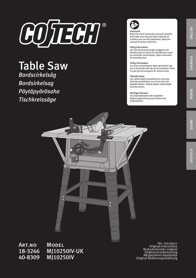
Table Saw
Art.no 40-8280 Model ST12
Please read theentire instruction manual before use and save it for future reference. Wereserve theright for any
errors in text or images and for making any necessary technical changes to this document. Ifyou should have
any questions concerning technical problems please contact our Customer Services.
Safety
• Make sure that everyone who operates thetable saw has read and understood thesafety instructions.
• The table saw must only be used if it is functioning correctly. Carefully observe all thewarnings and safety
instructions outlined in this manual. Ensurethat there are no disturbances that may affect workplace safety.
• Ensure that all safety devices are in place when thetable saw isused.
• Only use saw blades which conform to EN 847-1.
• Keep all thetable saw’s safety instructions accessible and in readable condition.
• Make sure that thetable saw is standing on asolid foundation.
• Check that none of theelectrical cables are damaged and that they are all properly connected.
• Keep children away from thetable saw when it is connected to thepower supply.
• This product must not be used by anyone (including children) suffering from physical or mental impairment.
Thisproduct should not be used by anyone who has not read theinstruction manual unless they have been
instructed in its use by someone who will take responsibility for their safety.
• Operators of thetable saw must not be distracted.
• If a second person is working next to thetable saw to take care of workpieces, thetable saw must
be equipped with atable extension. Thesecond person must never stand anywhere but at theend of
theextension table.
• Keep theworking area tidy. Cluttered surfaces and benches invite accidents.
• Wear suitable attire. Donot wear loose-fitting clothing or jewellery; they could be caught in moving parts.
Non-slip shoes are recommended for outdoor work. Wearahairnet or similar if you have longhair.
• Always use safetywear. Wearsafety glasses. Useadust mask or dust filter when working in dusty environments.
• Make sure theblade is fitted theright wayround.
• The table saw’s safety devices must not be removed or disabled.
• Disconnect thetable saw from thepower supply before servicing, changing attachments, changing blades
or cleaning thetable saw or measuring any workpiece placed onit.
• Disconnect thetable saw from thepower supply before correcting any potential hazards.
• Dust extraction equipment must be used when creating large amounts ofdust.
• Never use blades which are defective, blunt or of theincorrect size.
• High speed steel blades must not beused.
• The riving knife is animportant safety device which steers theworkpiece and prevents theblade for binding
in thecut and theworkpiece from kicking back.
• The blade guard must always be in place when making acut.
• The blade guard must be horizontal over thesawblade.
• Always use apush stick when rip-cutting narrow stock i.e. thinner than 120 mm. Thepush stick prevents
hands from coming too close to thesawblade.
• Replace thetable insert if it is damaged in anyway.
• Switch off themotor and disconnect thetable saw from thepower supply before leaving theworkplace.
• Disconnect thetable saw from thepower supply before moving it. Makesure that thetable saw is
connected correctly before switching iton.
• Servicing and repair work must only be carried out at anauthorized service centre.
• All safety devices and guards must be replaced immediately following any repairs or servicing.
• Never let children play with theproduct.
• Never use thetable saw if you are tired or under theinfluence of drugs, alcohol or medication.

3
ENGLISH
Specific safety rules
• If theaccompanying stand is not used, thetable saw must be placed level on astable, table-like platform.
Theworking height must be at least 800mm.
• When sawing, always stand in front of thetable saw and to theleft of thesawblade.
• Keep thework area free from foreign objects and potential hazards.
• Inspect theworkpiece for nails and screws and remove them before starting tocut.
• This table saw is designed exclusively for sawing wood or similar material.
• Onlygenuine parts and accessories may beused.
Despite the fact that the table saw has been fitted with all the necessary safety
devices and conforms to relevant safety standards, the following hazards still exist
• Danger to fingers and hands from therotating blade if theworkpiece is not handled properly.
• Danger of theworkpiece being ejected because it binds or is guided incorrectly.
• Danger to hearing due to loud noise if thework exceeds thepermitted noise level. Personal protective
equipment such as ear defenders must be used at alltimes.
• Danger caused by adefective saw blade. Regular checks should be made to make sure that theblade
isintact.
• Danger of electrocution if anincorrect mains lead isused.
• Whenever accessories are used, their instruction manuals must also be read and followed to ensure that
they are used in thecorrect way.
• No matter how many precautions one takes there is still therisk of unforeseen hazards.
• The chances of anaccident occurring can be minimized by adhering to thesafety instructions listed above.
Guide to Safety Symbols
Read theentire instruction manual.
Always use ear protection.
Always use safety glasses.

4
ENGLISH
Assembly
Note: Makesure that thesaw is disconnected from thepower supply before assembly, adjustment or servicing.
Legs
1. Lay thetabletop (1) onto aworkbench and
remove thewrapping (a) from around themotor.
2. Attach the4 legs (2) using thesupplied M6×16 mm
bolts, M6 nuts and washers. 2 bolts hold each leg
inplace. Finger-tighten thebolts.
On/off switch
Attach theon/off switch (3) to thetabletop using 2 of
theM6×16 mm bolts, M6 nuts and washers.
Cross members
Fit thecross members (4), 2 long and 2 short, to thelegs using 12 of theM6×16 mm bolts with nuts
andwashers. Finger-tighten thebolts.
1
2
a
3
4

5
ENGLISH
Table extension
Attach thetable extension (6) using thetwo struts (5) and thecross brace inside it. Use6 of theM6×16 mm
bolts with nuts and washers. Finger-tighten thebolts. Thetable extension can also be attached to theside of
thetable to widen it. Inthis case, theshorter struts should beused.
Dust extraction port
Attach thedust extraction port (7) to thelower blade guard
using 4 of theM6×16 mm bolts, M6 nuts andwashers.
Wheels
1. Attach thewheels to theback legs using 4 of
theM6×16 mm bolts, M6 nuts and washers.
Finger-tighten thebolts.
2. Turn thetable saw theright way up. Makesure
that all thelegs are touching theground.
Tighten all thenuts and bolts except for those in
thewheels.
3. Adjust theheight of thewheels so that they just
touch theground. Tighten their nuts andbolts.
6
5
7
8

6
ENGLISH
Riving knife
1. Remove thetable insert (9).
2. Adjust theriving knife (10) as shown in
thediagram. Loosentheadjusting screw (11)
alittle so you can adjust theknife. Retighten
thescrew. Refitthetable insert.
Blade guard
Bolt theblade guard (12) onto theriving knife using
theM6×25 mm bolt, M6 washer and thewingnut.
Hose holder
Attach thehose holder (14) to thetabletop
using 2 of theM6×16 mm bolts, M6 nuts and
washers. Connect thedust extraction hose (13)
to thebladeguard and to thedust extraction
port and then tidy thehose up by pushing it into
thehoseholder.
9
10
11
12
14
13
3–8 mm

7
ENGLISH
Accessory hook
Attach theaccessory hook (15)
for hanging theblade spanner
and pushstick on to theoutside
of therightfront leg using 2 of
theM6 nuts and washers (one nut
on theinside of theleg and one on
theoutside).
Transportation handles
Attach thetwo folding transportation
handles (16) to theface of thefront
legs using 4 of theM6×16 mm bolts,
M6 nuts and washers.
Rip fence
1. To attach therip fence rail to thetable
you will first need to bolt theclamp (17) to
thetabletop. Boltone of therip fence clamp’s
holders to thetabletop using anM6×30 mm
socketheadbolt, nut and washer and then slide
thepin on theend of theclamping handle into
thehole in theholder.
2. Then bolt theother clamp holder onto thetabletop
using theother M6×30 mm socket head bolt, nut
and washer.
3. Attach therip fence to therip fence rail (19) by
sliding it onto theslider plate (18) which is bolted
on using two M6×50 mm coach bolts, washers
and wingnuts.
4. The rip fence (20) can be mounted in two
positions, low profile
or high profile. Securetherip fence to therail by
tightening thewingnuts.
15 16
17
18
19
20

8
ENGLISH
Mitre gauge
5. Locate theend of therip fence rail in
theclamp(17). Lifttheclamping handle up
to locktherip fence rail in position and push
thehandle down to release it.
1. Attach thetwo slider rail brackets (22) to the slider
rail (21) using four M6×16 mm socket head bolts
and washers.
2. Attach theslider rail to thetable using four
M6×20 mm bolts, nuts and washers. Finger-
tighten thebolts. Note:Insert thespacer (23)
between thetable and thefront slider rail bracket.
3. Slide themitre gauge table (24) onto theslider rail.
InsertanM6×40 mm socket head bolt (25) and
wing nut at each end of theslider rail. Thesewill
prevent thesliding mitre gauge table from
comingoff.
17
2221
23
24
25

9
ENGLISH
6. Align thesliding mitre table so that it is parallel
to and level with thetabletop. Adjustit by
moving theslider rail. Extendthemitre gauge
fence to check that thetwo tables are level.
Whentheslider rail has been adjusted, thefour
bolts (30) can be tightened. Thetwo wing nuts
(29) on themitre gauge can be used for fine-
adjustments.
4. Adjust thelower bearing (26) on themitre
gauge table so thetable can slide freely but
nottooloosely.
5. When attaching themitre gauge (27) to thesliding
table, place thetwo plastic washers (28) between
them. Finger-tighten thebolt nearest thetable saw
so thegauge can swing round. Tighten theother
bolt which is attached to thelocking handle so
that themitre gauge is locked in position when
thehandle is depressed and can swing round
when thehandle is lifted.
7. Set themitre gauge at 90º to thesaw blade
by swivelling it up to thecam head bolt (31) in
thecorner of themitre table. Checkthat themitre
gauge is at right angles by placing atry square
against thesaw blade. Ifnecessary, adjust
thecam head bolt by undoing thenut under
themitre table. Testtheangle on apiece of
wastestock and fine-adjust if necessary.
26
27
28
29
30
31

10
ENGLISH
Electrical connections
• The power supply must be 230 V AC, 50Hz.
• The mains lead and any extension leads used must 3-core (twin and earth).
• The cablage must have aconductor cross-sectional area of 1.5 mm².
• Use astandard (BS1363) plug fitted with a13 ampfuse.
Note: Allelectrical connections and repairs should be carried out by aqualified electrician.
Use
Placement
• Place thesaw on afirm and level surface.
• The table legs have holes in thebottom for bolting to thefloor if required.
• Make sure that there is enough space around thesaw for thework to be carried out safely.
• Never lift thetable saw up by thetabletop, always use asack truck, pallet truck or suitable lifting equipment.
Fitting and replacing the saw blade
Blade height setting
The saw blade can be raised and lowered over
arange of 80 mm with thehelp of theelevating
and lowering handle (32).
Setting the bevel angle
1. After first undoing thelocking knobs (33, 34) on thefront and back of thetable saw, thesaw blade can be
bevelled freely from 90º to45º.
2. Set thedesired bevel angle and then tighten thelocking knobs.
32
33 34

11
ENGLISH
Changing the blade
Note: Carefully observe thedirection of rotation markings on thesawblade.
1. Make sure thesaw is switched off and unplugged.
2. Remove thebladeguard. 3. Unscrew thefour table insert retaining screws and
remove theinsert.
4. Raise thesaw blade as high as it will go and undo
theblade locking nut using thesupplied spanner.
Note:The nut has aleft-hand thread.
5. Remove theflange and theblade.
6. Fit thenew blade and replace theflange making sure that thelugs on theflange fit into theslots on
thespindle. Tighten thenut securely.
7. Check theriving knife setting and adjust it if necessary.
8. Refit thetable insert and thebladeguard.
Sawing
Note: Alwaystest thesaw blade on asuitable workpiece following achange of blade. Checkthat all theangles
are correct and that thesaw cut is clean. Adjustif necessary. Abit of practice is usually needed to achieve
theperfect result. Trysawing different types of wood and different rates of feed and practice changing
thesettings safely until you feel comfortable using thesaw. Alwaysuse thesupplied push stick if necessary.
Note: Keepyour hands well away from theblade.
Ripping (parallel cutting)
• Always use therip fence for sawing parallel along thelength of theworkpiece.
• Use thehigh profile edge of therip fence for workpieces over 120 mm in height.
• Use thelow profile edge of therip fence for workpieces under 120 mm in height.
Crosscutting
Always use themitre gauge for square crosscutting, mitre crosscutting or bevel crosscutting.

12
ENGLISH
Sawing wide workpieces
• Set theripfence.
• Make sure that your left hand is resting on afirm
surface to steady you. Ifnarrow offcuts are
produced during thesawing, the workpiece may
only be fed through theblade using your right
hand or with thehelp of apushstick.
Sawing narrow workpieces
• Set theripfence.
• Feed theworkpiece through theblade with
bothhands.
• When your hands begin to near theblade, you
should use apush stick to feed theworkpiece
past theblade in asteady motion.
Sawing edging and moulding
• Set therip fence to thelow profile.
• Feed theworkpiece into theblade using thepush
stick until theedge of theworkpiece is in thearea
of theriving knife.
• Make sure that long workpieces do not fall
onto thefloor after sawing by attaching atable
extension onto thetable.
Crosscutting narrow workpieces
Use themitre gauge to guide you whenever making
any kind of crosscut.
Note: Neverremove offcuts from around
thesawblade with yourhands.
Sawing bevels, grooves, rebates, etc
• When ripping abevel, thecut should be made
so that thecut-off strip falls away from themain
workpiece on theopposite side of theblade to
theripfence.
• When cutting grooves or rebates, remove
theblade guard and lower thesaw blade to
thedesired height. Makesure that theworkpiece
can be fed over theblade without dificulty.
Note: The blade guard in thepictures has been removed only for thepurposes of allowing aclearer view of
themethod of operation or construction.

13
ENGLISH
Length stop
The mitre guage fence has alength stop for making
repetitive cuts of thesame length.
Troubleshooting guide
The motor does notstart. • Saw not plugged in.
• Is thewall socket live?
• Is themains lead /extension lead damaged or disconnected?
• Has themotor overheated and tripped thethermal fuse?
Letthemotor cool down and then try itagain.
• Defective switch.
Saw makes unsatisfactory cuts. • The blade is blunt, change it.
• Check that theblade is not mounted backwards.
Material pinches blade when ripping. • Riving knife not aligned correctly withblade.
• Warped wood, edge against fence not straight.
• Feed theentire workpiece past theblade before letting go of it
(use apush stick if necessary). Inspect thesaw blade, change
ifnecessary.
Material builds up on theriving knife. • Check/adjust theriving knife so that it is in line with thesaw blade,
make sure that thekerf of theblade is not narrower than
therivingknife; change theblade if it is toothin.
The workpiece or parts of it are
thrown backwards.
• The rip fence is not parallel with thesaw blade, adjust.
• Check/adjust theriving knife so that it is in line with thesawblade.
Feedtheentire workpiece past theblade before letting go of it
(use apush stick if necessary).
• Inspect thesaw blade regularly, change if necessary.
The saw blade cannot be tilted
without theuse offorce.
• Use abrush and vacuum cleaner to remove all sawdust from
theadjustment mechanisms, then carefully lubricate.
Heavy vibrations. • Check that all bolts and nuts are secure andtight.
• Make sure that theblade is not damaged and is fitted correctly.
• Make sure that thetable saw is on aflat level surface and that
all four legs are on theground. Reposition or fasten to floor
ifnecessary.
The motor stops or theworkpiece
gets burn marks when ripping.
• The blade is blunt, change it.
• Use aslower feedrate.
• Check/adjust theriving knife so that it is in line with
thesawblade.

14
ENGLISH
Care and maintenance
Note: Switchthetable saw off and unplug it before carrying out any repairs or adjusting any settings.
• Always keep theinstruction manual together with themachine.
• Keep theworking areatidy.
• Wear eye protection when cleaning.
• Do not clean theplastic components of thetable with strong detergents. Amild detergent on amoist cloth
is recommended. Neverpour water onto thetablesaw.
• Check thecondition of thesaw blade regularly. Donot use saw blades that are blunt, damaged or deformed.
• Replace thetable insert as soon as it is worn. Keepthetabletop free ofresin.
• Remove sawdust frequently to prevent blockages and fire hazards.
Disposal
This product should be disposed of in accordance with local regulations.
Ifyou are unsure how to proceed, contact your local authority.
Specifications
Voltage 230 V, 50Hz
Power 2200W
Duty cycle S6/40%
Speed 2800rpm
Saw blade 315×30×3.6/2.0Z24
Extraction port 100mm
Blade tilt 90°–45°
Depth of cut 80 mm/90°, 48 mm/45°
Table size 800×550mm
Table extension size 800×400mm
Working height 800mm
Weight 46kg

15
SVENSKA
Bordscirkelsåg
Art.nr 40-8280 Modell ST12
Läs igenom hela bruksanvisningen före användning och spara den sedan för framtida bruk.
Vi reserverar oss för ev. text- och bildfel samt ändringar av tekniska data.
Vid tekniska problem eller andra frågor, kontakta vår kundtjänst (se adressuppgifter på baksidan).
Säkerhet
• Se till att alla som arbetar med maskinen har läst och förstått säkerhetsanvisningarna.
• Maskinen får endast användas om den fungerar tekniskt korrekt. Beaktaalltid de direktiv,
säkerhetsbestämmelser och faror som är angivna ibruksanvisningen. Åtgärda genast de störningar som
kanpåverka säkerheten.
• Alla skyddsanordningar måste vara monterade när maskinen används.
• Endast verktyg som motsvarar den europeiska normen EN 847-1 får användas.
• Förvara maskinens alla säkerhetsföreskrifter kompletta, lättillgängliga och iläsbart skick.
• Se till att maskinen står stadigt på fast underlag.
• Kontrollera att alla anslutningskablar är hela och korrekt anslutna.
• Håll barn borta från nätansluten maskin.
• Produkten får inte användas av personer (inklusive barn) med nedsatt fysisk eller mental förmåga. Denfår
inte heller användas av personer utan tillräcklig erfarenhet och kunskap ifall de inte har fått instruktioner om
användningen av någon som ansvarar för deras säkerhet.
• Personer som arbetar vid maskinen får inte störas.
• Om enandra person arbetar vid bordscirkelsågen för att ta hand om överblivna arbetsstycken, måste
maskinen vara utrustad med enbordsförlängningsskiva. Denandra personen får inte stå på någon annan
plats än vid slutet av bordförlängningsskivan.
• Håll arbetsplatsen ren. Belamrade ytor och bord inbjuder till olyckor.
• Bär lämplig klädsel. Bäringa löst sittande kläder eller smycken, de kan fastna iroterande delar.
Halksäkraskor rekommenderas vid arbete utomhus. Bärhårnät eller liknande om du har långthår.
• Bär alltid skyddsutrustning. Bärskyddsglasögon. Användockså dammfilter eller skyddsmask vid
dammande arbeten.
• Beakta motorns och verktygets rotationsriktning.
• Maskinens säkerhetsanordningar får inte demonteras eller göras obrukbara.
• Ställoperationer, justering, mätning och rengöring får endast utföras när maskinen är helt bortkopplad
frånelnätet.
• Koppla bort maskinen från elnätet innan du åtgärdar eventuella störningar.
• I samband med dammiga arbetsmoment måste maskinen vara ansluten till enutsugningsanordning.
• Använd endast välslipade och felfria sågklingor.
• Sågklingor av snabbstål får inte användas.
• Klyvkniven är enviktig säkerhetsanordning som styr arbetsstycket, förhindrar bakslag och att snittet sluts
bakom sågbladet.
• Vid varje arbetsmoment måste skyddskåpan sänkas ner över arbetsstycket.
• Skyddskåpan måste stå vågrätt över sågbladet.
• Vid längdsågning av smala arbetsstycken, tunnare än 120 mm, måste ens.k. påskjutare användas.
Påskjutaren måste användas för att förhindra att arbetsmoment utförs med händerna inärheten av sågklingan.
• Byt ut bordsinlägget om det på något sätt skadas.
• Stäng av motorn och koppla bort maskinen från elnätet när du lämnar arbetsplatsen.
• Koppla bort maskinen från elnätet också vid obetydlig flyttning av maskinen! Försäkra dig om att maskinen
nätansluts på ettkorrekt sätt innan den startas pånytt.
• Installationer, reparationer och service får endast utföras av auktoriserad personal.
• Samtliga skydds- och säkerhetsanordningar måste monteras omedelbart efter avslutad reparation eller tillsyn.
• Låt aldrig barn leka med produkten.
• Använd inte apparaten om du är trött, påverkad av alkohol, medicin eller andra droger.

16
SVENSKA
Särskilda säkerhetsföreskrifter
• Om inte den tillhörande benställningen används, måste maskinen ställas upp på ettstabilt, bordsliknande
ställ där den står jämnt. Arbetshöjden ska uppgå till minst 800mm.
• När sågningsarbete utförs stå alltid framför maskinen, till vänster om sågklingan.
• Maskinens arbets- och kringområde måste hållas fritt från främmande föremål för att förebygga olyckor.
• De arbetsstycken som ska bearbetas måste vara fria från främmande föremål som spikar eller skruvar.
• Bordscirkelsågen är konstruerad uteslutande för bearbetning av trä eller träliknande material.
• Endastoriginalverktyg och tillbehör får användas.
Trots att nödvändiga skyddsanordningar installerats enligt gällande föreskrifter
återstår följande faromoment vid användning av bordscirkelsågen
• Skaderisk för fingrar och händer p.g.a. den roterande sågklingan om arbetsstycket inte styrs fackmässigt.
• Skador kan uppstå genom att arbetsstycket slungas iväg p.g.a. att det hålls fast eller styrs felaktigt.
• Hälsorisk p.g.a. buller. Vidarbetet överskrids den tillåtna bullernivån. Personlig skyddsutrustning som
hörselskydd måste ovillkorligen användas.
• Skador p.g.a. defekt sågklinga. Kontrollera regelbundet att sågklingan är oskadad.
• Fara p.g.a. elström om inte korrekt anslutningskabel används.
• När särskilda tillbehör används, måste den bruksanvisning som har skickats med tillbehören läsas igenom
noggrant och följas.
• Trots alla vidtagna åtgärder kan ändå icke uppenbara risker finnas.
• Riskerna kan minimeras om säkerhetsföreskrifterna ibruksanvisningen beaktas och åtföljs isin helhet.
Produktmärkning med säkerhetssymboler
Läs hela bruksanvisningen!
Använd alltid hörselskydd.
Använd alltid skyddsglasögon.

17
SVENSKA
Montering
Obs! Kontrollera alltid att sågen är bortkopplad från elnätet innan montering, justering eller annat arbete utförs.
Ben
1. Lägg bordsskivan (1) på enarbetsbänk och ta
bort förpackningsmaterialet (a) under motorn.
2. Montera de 4 benen (2) med medföljande
M6×16skruvar, M6 brickor och muttrar. 2 skruvar
till varje ben. Draåt skruvarna lätt förhand.
Strömbrytare
Montera strömbrytaren (3) ibordsskivan med 2 st.
M6×16 skruvar, M6 brickor och muttrar.
Stag
Montera stagen (4), 2 längsgående och 2 tvärgående, ibenen med 12 st. M6×16 skruvar, M6 brickor
ochmuttrar. Draåt skruvarna lätt förhand.
1
2
a
3
4

18
SVENSKA
Förlängningsskiva
Montera förlängningsskivan (6) med de 2 stagen (5) ibordsskivan och tvärstaget. Använd6 st. M6×16 skruvar,
M6 brickor och muttrar. Draåt skruvarna lätt för hand. Förlängningsskivan kan också monteras på sidan som
bordsbreddning. Använddå de kortare stagen.
Utsugsstosen
Montera utsugsstosen (7) på det nedre sågklingsskyddet
(8) med 4 st. M6×16 skruvar, M6 brickor och muttrar.
Hjul
1. Montera hjulen på de bakre benen med 4 st.
M6×16 skruvar, M6 brickor och muttrar. Draåt
skruvarna lätt förhand.
2. Vänd sågen så att den står rättvänd. Setill att alla
ben vilar mot golvet. Draåt alla skruvar ibord, ben
ochstag.
3. Justera in hjulen så att de precis vidrör golvet.
Draåt skruvarna.
6
5
7
8

19
SVENSKA
Klyvkil
1. Ta bort bordsinlägget (9).
2. Justera in klyvkilen (10) som bilden visar.
Lossanågot på justerskruven (11) så att kilen
kan justeras. Drasedan åt skruven igen.
Monteratillbaka bordsinlägget.
Skyddskåpa
Montera skyddskåpan (12) på klyvkilen med 1st.
M6×25 skruv med kullrigt huvud, M6 bricka
ochvingmutter.
Slanghållare
Montera slanghållaren (14) ibordsskivan med
2 st. M6×16 skruvar, M6 brickor och muttrar.
Anslututsugsslangen (13) till fästet på skyddskåpan
och till fästet på utsugsstosen. Klämfast slangen
islanghållaren.
9
10
11
12
14
13
3–8 mm

20
SVENSKA
Förvaringskrok
Montera kroken (15) för förvaring av
sågklingsnyckeln och påskjutaren på
den högra bensidan. Använd2 st.
M6 muttrar och brickor. Enmutter på
benets utsida och enpå insidan.
Transporthandtag
Montera de 2 transporthandtagen
(16) på benen på sågens framsida.
Använd4 st. M6×16 skruvar,
M6brickor och muttrar.
Längdanslag
1. Montera längdanslaget. Fäst först en av hållarna
för längdanslagets låsklaff (17) i bordsskivan och
skjut sedan in låsklaffen i hålet.
2. Sätt sedan den andra hållaren på låsklaffen och
fäst den i bordet. Använd 2 st. M6 sexkantsskruv
invändig, brickor och muttrar.
3. Montera anslagsskenan på längdanslaget.
Fästmellanblecket (18) i längdanslaget (19).
Använd 2st. M6×50 vagnsbultar, brickor
ochvingmuttrar.
4. Skjut sedan på anslagsskenan (20) för endera låg
eller hög anslagsyta. Draåt vingmuttrarna.
15 16
17
18
19
20
This manual suits for next models
1
Table of contents
Languages:
Other CO/Tech Saw manuals

CO/Tech
CO/Tech J1X-JF3-255/07 User manual
CO/Tech
CO/Tech 2502W User manual
CO/Tech
CO/Tech TC-RM-180E User manual
CO/Tech
CO/Tech J1x-JF2-210 User manual

CO/Tech
CO/Tech TC180C-UK User manual

CO/Tech
CO/Tech TC180I-UK User manual
CO/Tech
CO/Tech CSB315 User manual
CO/Tech
CO/Tech J1X-KZ2-210-UK User manual
CO/Tech
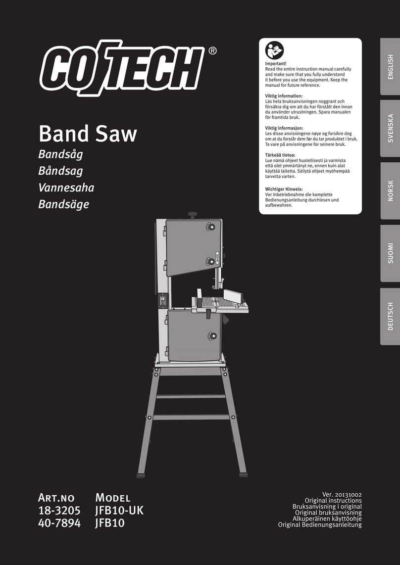
CO/Tech JFB10-UK User manual
CO/Tech
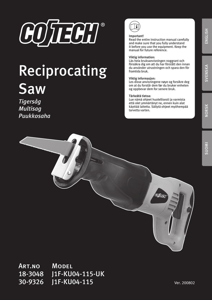
CO/Tech J1F-KU04-115-UK User manual
