COairo CD200 User manual

CoAiro CD200 USER MANUAL
INSTALLATION BY A HVAC PROFESSIONAL IS RECOMMENDED
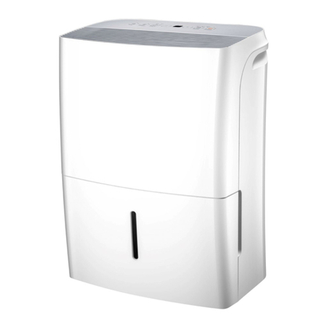
The CoAiro CD200 is a split system dehumidifier
with sensible cooling
that is integrated into the heating and cooling
system to provide the
ultimate in comfort, health and property protection
&
&&
14752 Yorba Ct Chino CA
91710 US 888-977-1520 support@coairo.com

CoAiro CD200 DEHUMIDIFIER Installation, Operation & Service Instructions CoAiro CD200 DEHUMIDIFIER Installation, Operation & Service Instructions
Warranty Registration
Parts Included
Specifcations
Installation Dehumdifier
Condenser Setup
Charging the System
The On-Board De-humidistat
External Control
Maintenance
Important Notes
Features
Safety Notes
Dehumidifier Spare Parts
Condensing Unit Spare Parts
Limited Warranty
Warranty Exclusions 17
16
15
15
14
13
13
12
6
4
3
2
2
1
1
1
Install dehumidifier according to all applicable local,state,and national codes.
Ensure that the discharge air is not directed at people, or over water in spa and pool areas.
The condensing unit must always be protected from elements such as snow, rain, and
sunlight although the device can be installed outdoors.
If the device is meant for use near water, spa or a pool, make sure that there are no possible
chances of the unit being splashed or/and falling into the water. Also, make sure that it is plugged
into an outlet that is protected by the GFI (Ground Fault Interrupt) circuit.
This type of dehumidifier is designed in such a way that it is suitable for indoor installation
in a room that is perfectly protected from flooding and rain.
Always connect your dehumidifier using a grounded, dedicated electrical connection that is
GFCI protected with at least 15 amp capacity.
The use of any other type of wiring will void your warranty.
1.Important Introduce
The CoAiro CD200 is a split system dehumidifier with sensible cooling
that is integrated into the heating and cooling system to provide the
ultimate in comfort, health and property protection through:
•Dehumidification
• Sensible Cooling
• Fresh Air Ventilation (Optional)
• Air Filtration
The two-piece design allows the sensible heat load generated from
dehumidifying the house to be released in the outside condensing unit,
thus eliminating additional cooling and reducing air conditioner run time.
It is made with a low voltage control system.
It has the R410A refrigerant, which is generally environmentally friendly.
It features an auto-restarting operational system after power outages.
It used the standard MERV-11, which offers superior air filtration.
The device has a quiet operation.
It is designed with a long life and high-efficiency impeller.
It has an optimized and perfectly patented air-to-air heat exchanger.
The device brags of industry-leading effectuality.
4,300 BTU cooling.
2.Features
3.Safety Notes
1

2 3
CoAiro CD200 DEHUMIDIFIER Installation, Operation & Service Instructions CoAiro CD200 DEHUMIDIFIER Installation, Operation & Service Instructions
The design of the dehumidifier is suitable for indoors space that is protected from any forms
of flooding or rain.
For ease of testing and operation, it may be helpful to put the test switch and indicator lights in
a convenient location.
Your dehumidifier should only be repaired by a qualified technician.
Do not insert objects or your fingers into the inlet or discharge.
Do not use water to clean the exterior of the dehumidifier. To clean unit, unplug from power, then
use a damp cloth to wipe the exterior.
Do not stand on dehumidifier or place objects on it.
Unless otherwise noted, all maintenance should be done with the unit power off.
It is important to install the dehumidifier in a room that has enough space.This is to allow you
to access the side and/or back panels easily for service and maintenance purposes.
Be sure to follow your GFCI maintenance instructions.you will typically need to test the operation
of the trip circuit monthly.
support@coairo.com
4.Warranty Registration
Prior to installation of the unit,write down the serial number and date of purchase. You will need
this information if you need assistance in the future. The data label on the side of your unit has
the necessary information.
Model Number: CoAiro CD200
Serial Number: Date of Purchase:
For additional questions concerning your dehumidifier:
Contact your installing contractor
Contact US:
5.Parts Included
The CoAiro CD200 Leveling Feet.
The CoAiro CD200 Installation Instructions.
The CoAiro CD200 Condensing Unit.
The CoAiro CD200 Dehumidifier.
6.Specifcations@ 80°F/60% RH
Dimensions:
Width:
Height:
Length:
Weight:
20.25"
21.75"
38"
109 lbs
DEHUMIDIFIER
Capacity@80℉/60%RH: 200 Pints Per Day
Airflow @ 0.0” SP 300 CFM
Operating Temp. Range 33-105°F
Operating Relative
Humidity Range: 36%-90%
COP: 2.8 L/kWh
Refrigerant: R410A
7.6 Amps
115V/60Hz
/Single Phase
Amperage Usage:
Power Supply:
Outlet Requirement: 15 Amp,
3 Prong, GFCI
Sound Level: 60 dBa
ETL Listed: YES
CONDENSER
Current Draw 9.7 Amps
Minimum Circuit
Ampacity:
Refrigerant: R410A
40°F Min,
115°F Max
115V/60Hz
/Single Phase
Operating Range:
Power Supply:
Dimensions:
Width:
Height:
Length:
Weight:
20.25"
21.75"
38"
109 lbs
Power Cord: Hard-Wired
20 Amps
Maximum Fuse
/ Breaker: 20 Amps

4 5
CoAiro CD200 DEHUMIDIFIER Installation, Operation & Service Instructions CoAiro CD200 DEHUMIDIFIER Installation, Operation & Service Instructions
7.Installation Dehumdifier
The CoAiro CD200 can be installed in various locations in order to meet the needs
of the client. However, it is important to observe the factors highlighted below during the
installation process:
The device is designed to best suit indoor installation in a room that is protected
from flooding and rain.
Make sure you install the device in a room with enough space to allow easy access
to the side and back panels during service and installation. The space should also
allow easy access to the filter cover panel.
You should ensure that the air discharged by the device is not directed over water
in the pool areas, or at people.
Make sure that there are no possible chances that the device could be splashed
or fall into the water. Also, ensure that it is plugged into a GFI (Ground Fault Interrupter).
You should never use the device on a table or a bench.
You should not place the device directly to structural members.
Make sure you provide isolation to reduce operational noise and/or vibration.
The drain pan should always be placed beneath the dehumidifier unit if it is located
above a room where water leakage is more likely to occur.
Place the device on supporters that raise its base to at least 6” above the top flanges
on the drain pan below it. Raising the dehumidifier will help the device to drain water
freely with gravity.
The device can be suspended using a steel hanger or any other suitable alternative
from structural members, the unit should be supported from beneath. Ensure
that you do not hang from ends or sides.
Make sure that you place a drain pan beneath the dehumidifier if it is
suspended on top of a finished area or a space where water leakage is
more likely to occur.
7.1 Electrical Requirements
The device plugs into a NEMA rated receptacle. The number of Amps drawn by the
device may vary depending on the operational conditions. In most cases, a GFI
protected circuit is necessary. It is important to install the remote control panel in the
central area of the room where it will be able to sense the RH of the room on turning it on.
It is important to install the remote control panel in the central area of the room where it
will be able to sense the RH of the room on turning it on.
In order to maintain proper drainage, it is advisable that the unit should be
mounted such that the drain outlet is 4” or more above the floor drain, and must be
totally supported beneath the base.
CAUTION:
7.3 Condensate Water Removal
In normal cases the condensate drain by the aid of gravity through the drain port. It is
advisable that you make use of the 3/4” male PVC NPT pipe. Also, rout the drain pipe
and ensure it is draining well. If possible, install a trap too. You should always be careful
when installing the drain pipe to the drain port. You can use an adjustable wrench to
safeguard the drain port. In addition, an optional water pump kit can be installed in a
case where a lift is necessary for disposing of the condensate. You can order the
condensate pump kit from CoAiro Dry.
During the installation of the drain hose ensure that the base of the device is at least 6”
above the ground. After this, coil the drain hone beneath itself or just position a spacer
to lift the hose at least 1” above the ground after the hose gets in contact with the
ground. This process will create a trap that makes sure that the unit drains well.
7.2 Plug Holes Using
In order to maintain proper drainage, it is advisable that the unit should be
mounted such that the drain outlet is 4” or more above the floor drain, and must be totally
supported beneath the base.
CAUTION:
Coll the control panel and the dehumidifier. Make sure that you safely route the control wiring
to help avoid damage during the installation process.
Make sure you do not cross the wires when you are connecting the device and the remote
control panel too.
In most cases the remote control panels of the CoAiro CD200 are powered by the low
voltage (24 VAC). It must never be connected to any sort of high voltage circuit. The
remote control and terminals are numbered and labeled to prevent confusion. Make sure
you read the electrical schematic available inside the access panel of the device or in this
manual before you make any control connections.
7.4 HangingDiagram
Install the drain

6
CoAiro CD200 DEHUMIDIFIER Installation, Operation & Service Instructions CoAiro CD200 DEHUMIDIFIER Installation, Operation & Service Instructions
SupplyDuctKit(P/N4028607)
A factory designed supply kit can be bought to match the 10” ducting to both inlet and outlet
of the CoAiro CD200.
You can contact the manufacturer or may find it at your local dealer’s store.
The P/N 4028610 Return Duct Kit
A factory designed return kit can be bought to match the 12” ducting of the device.
You can call the manufacturer or may find it at your local dealer’s store.
The condensing unit demands that a dedicated 20 Amp 120VAC circuit capacity. Makes sure
you install a well-sized branch circuit disconnect that is 20 Amp within the sight of the condenser
unit. The installer should supply the power wiring for the purpose of condensing unit. In any case,
the power wiring should have a minimum of 20 Am circuit Ampacity, and it should be run
through a rain-tight conduit. The condensing unit should be grounded as per the applicable codes.
\f
\b
??
???\f
7.5 The P/N 4028607 Supply Duct Kit
8.CondenserSetup
8.1ALocation
The condensing unit is designed to be installed outdoors in a space that is protected from extreme
weather (rain, wind, etc.). Do not place the condensing unit in direct sunlight.
•
Place the condensing unit at least 1"above ground level.
Place the condensing unit as close as possible to the dehumidifer to minimize the length of
the connecting lines. The maximum line set length is 50 feet.
•
•
Ensure the mounting of the condensing unit can withstand strong winds and earthquakes when
mounting above ground level.
•
The condensing unit may be mounted to a wall (with brackets)or placed on a roof.
•
Mount the base of the condensing unit to a sturdy level pad (or bracket) using 3/8" (10mm) bolts.
Avoid directing the discharge air at people.
•
Ifusednearawatersource;be certain there is no chance the dehumidifer could fall into the water or
get splashed and that it meets NEC standards.
•
DO NOT use the condensing unit as a bench or table.
•
Do not place the condensing unit where the sound and vibration caused by running the unit will a
cause a nuisance. Vibration dampening material may be installed between the condensing unit
base and the mounting pad if required.
•
Allow sufcient clearance to handle the unit’s overall dimensions.
Place the condensing unit where there is adequate space for the unit and the air required by the unit.
Install the condensing unit with space to access the top and side panels for maintenance
and service.
•
•
•
8.2 The Procedure of Field Wiring the Condensing Unit
First of all, take off the top panel, by simply removing the screw present on the dehumidifier
securing the condensing unit.
•
Second, loosen the two-strain relief bloc screws.
•
Insert the control and power wires via the strain relief block.
•
Forth, connect the control wires and the power supply wires to the matching terminals on the
terminals board.
•
Make sure you ground the condensing unit with the observance of the national and local
electrical codes.
•
Ensure that you secure the control and power wires to the strain relief block by simply tightening
the available screws.
•
Lastly, reinstall the top panel by inserting the screw that secures the condensing unit.
•
8.3 The Line Set
You should ensure that the lines are perfect for use with the R410a.
You should never crush the line sets and ensure that you may only allow an average bend
radius of 2 inches.
Ensure that the ends of the line sets are well-covered to avoid debris and dirt from
penetrating the lines during the installation process.
Secure the lines nearer to the structure using the isolating hardware to avoid any chances
of vibration transmission to the entire building.
Isolate and seal the openings where the line are routed into the building.
Make sure you insulate the suction (gas) line set to prevent chances of water condensation
occurring within the suction line.
Ensure that you fully flush the line sets with an inert gas prior to and/or during the brazing
process to prevent chances of oxidation occurring in the line sets.
Ensure that you release the inert gas while holding the charge and also remove the plugs
connecting to the dehumidifier lines prior to brazing.
You should never overheat the line sets connected to the device or the condensing unit
during the brazing process.
You should be aware of the most appropriate locations of the condensing (outdoor unit) and
the dehumidifier (indoor unit) when installing the lines.
•
•
•
•
•
•
•
•
•
•
7

8 9
CoAiro CD200 DEHUMIDIFIER Installation, Operation & Service Instructions CoAiro CD200 DEHUMIDIFIER Installation, Operation & Service Instructions
Warning:
The POE (Polyester) oils used by the HFC-410A refrigerant system absorb moisture quickly. It is thus;
very essential to keep the refrigerant system closed all the time. Ensure that you do not remove
service valve stub caps or the line set caps until you are ready to complete the connections. In a case
where you are using high-pressure gas, for instance, dry nitrogen to pressurize the air conditioning
system or refrigeration, it is important to maintain the pressure at 1 to 2 PSIG.
Caution:
Brazing flux and alloys contain materials that are hazardous to the health. You should, therefore, avoid
breathing in the fumes or vapors released from the brazing operations. It is important that you perform
the operation in a well-ventilated space. Put on protective goggles and gloves or use the face shield to
protect your body against burns. Ensure that you wash your hands using soap and running water after
you handle the brazing flux and alloys. In order to prevent the stripping of the numerous caps utilized,
an averagely sized wrench must be used and should be fitted snugly over the cap prior to tightening.
Also, give the braze joint some time to cool before you remove the wet rag from the service valve. You
should be cautioned that temperatures that are above 250 degrees can damage the seals. You can
use the silver alloy brazing rods that have five percent minimum silver alloy for the purpose of copper
to copper brazing. In the case for copper to steel and copper to brass brazing, make use of the 45%
minimum silver alloy.
Warning:
When using any dehumidifier you should be aware that the device bears along property safety
hazards, explosion, and fire. If you fail to observe the safety measures highlighted in this manual,
death, personal injury, and property damage is more rampant. Make sure that you never use oxygen to
purge or pressurize refrigeration line sets. When oxygen is exposed to open flame or sparks it can
cause an explosion and/or fire that could result in associated hazards. It is important to note that there
is a service port in the CoAiro CD200 dehumidifier especially on the gas line, and on both stub
tubes of the condensing unit. The service ports can be utilized to release and introduce nitrogen during
the brazing process.
Caution:
The CoAiro CD200 dehumidifier is whipped from the manufacturer pressurized with the charge of
inert gas together with a rubber plug in the lines. You can purge the inert gas out of the device by
simply removing the rubber plugs present in the gas and liquid line to release the inert gas prior to
connecting the line sets.
Note: In a case where there is no pressure in the CoAiro CD200dehumidifier when the first plug
is released, ensure that you check the device for leaks and damage before you proceed withthe
installation.
You can make use of the following procedure to perfectly
set the lines to the device:
First of all, purge the inert gas present in the device by simply removing the rubber plugs present
in the gas and liquid lines to release the gas before you proceed to connect the line sets.
Place a heat shield, for instance, a wet rag against the CoAiro CD200 dehumidifier and all
around the piping stubs. Ensure that the heat shield is also in place to help protect the cabinet from
any possible heat damage.
If necessary, swage the gas and liquid lines to fit with the dehumidifier lines.
Ensure that you purge the line set and the dehumidifier lines with the inert gas (dry nitrogen) to
prevent any possible chances of oxidation during the brazing process. Make sure that you flow
dry nitrogen throughout the lines set up to the dehumidifier lines.
Next, braze the line sets up to the dehumidifier lines.
Ensure that you remove the heat shield soon after brazing and enable the connected lines to cool.
•
•
•
•
•
•
You can make use of the following procedure to connect the
condensing unit to the line set:
Make sure that you first cut the line set to the desired length. Cover the cut ends of the line sets.
Use the flare fittings that are included in the condensing unit to fit the lines onto the line set where
needed.
Carefully swage the gas lines and the liquid lines where necessary to ensure that they fit onto the
line stubs and bind with fare fittings.
Next, remove the service valve cores and caps.
You can purge the lines with the inert gas such as dry nitrogen to prevent the occurrence of
oxidation during the brazing process.
Ensure that you braze the line stubs to the line sets.
On completion of the above step, remember to apply a light coating of oil to the flare fittings and
threads present on the condensing unit valves.
Kick-start each and every flare nut on the parallel flare fitting present on the condensing unit valves
using your hand, and make sure the threads are engaged well. Ensure you tighten the flare units
well by hand.
Carefully tighten the flare nuts to their corresponding flare fittings on the condensing unit valves.
On completion of this procedure reinstall the service valve caps and cores.
•
•
•
•
•
•
•
•
•
•

10
Uni-P H20 200C DEHUMIDIFIER Installation, Operation & Service Instructions Uni-P H20 200C DEHUMIDIFIER Installation, Operation & Service Instructions
During the process of checking the system charge, you can make use of the manifold gage, which
features low loss of anti-blowback fittings. The manifold gage that is used with the HFC-410A
refrigerant should be able to handle the higher system operating pressures. In general, the gages
should be rated for utility with the high side operating pressure of about 0 to 800 psig, and the low side
operating pressure of thirty inches of the vacuum to 250 psig. Anti-flutter gages and damper gages are
often recommended. The gage hose, on the other hand, should be rated for use of up to 800 psig of
pressure together with an average burst rating of 4000 psig.
Leak Test the Dehumidifier and the Line Set
The Manifold Set
Caution:
The EPA (Environmental Protection Agency) prohibits the deliberate venting of HFC refrigeration
during the disposal, repair, service, and maintenance of appliances. The approved methods of
reclaiming, recycling or recovery should be observed.
Warning:
In a case where you are using a high-pressure gas like dry nitrogen to pressurize air conditioning or
refrigeration, it is recommended that you make use of a regulator that can perfectly control the
pressure down to one or two PSIG.
Caution:
The leak detector should be able to sense the HFC refrigerant.
Warning:
The refrigerant gas may be harmful if inhaled. For that reason, the refrigerant must be recovered and
used responsibly. Failure to observe this aspect may result in death or serious bodily injuries.
When it comes to leak-testing the procedure highlighted
below can be of great importance:
Connect the manifold HFC-410A gage set for the high-pressure hose to the
suction gas line using the service port. By connecting the high-pressure hose to
the gas line via the service port you will help to protect the manifold gage from
the negative effects of high pressure during the leak testing process. Ensure
that you cap the liquid line present on the manifold gage service port.
Ensure that all valves present of the manifold gage on the outdoor unit are closed. Connect an
HFC-410A refrigerant cylinder to the center port present on the manifold gage set.
Position the cylinder of the HFC-410A refrigerant in such a way that it delivers vapor only. Open
the valves on the refrigerant and ensure that the HFC-410A amount is at a maximum of 57g
(two ounces) of refrigerant or at maximum 3PSI. Close the valve on the cylinder of HFC-410A
and the valve present on the high-pressure manifold gage set.
Make sure that you disconnect the cylinder of the refrigerant from the manifold gage set.
Next, connect the cylinder of inert gas (dry nitrogen) using a pressure regulating valve to the
middle port of the manifold set.
Adjust the inert gas (dry nitrogen) pressure regulator to averagely 150 psig. Then open the
valve on the side of the manifold gage to pressurize the dehumidifier and line set.
Ensure that you close up the valve on the inert gas cylinder. Then close the valve present on
the high-pressure side of the manifold set.
Give the system some time to rest.
Check all threaded and brazed joints for any possibilities of leaks using the leak detector
designed to sense the HFC refrigerants.
After you complete the leak testing process, you may disconnect the inert gas cylinder from the
middle port of the manifold gauge and also disconnect the high-pressure hose present on the
manifold gage from the suction gas line service port.
Evacuating the Dehumidifier and the Line Set
First of all, remove the valves from the service ports on the gas and liquid line stubs using the no-
loss valve core removal gadgets.
Connect a quarter feet SAE in-line tee unto the gas stub valve core removal
port.
Next, connect the manifold gage set low-pressure side to one of the ports present on the quarter
feet SAE in-line tee.
Forth, connect the micron gage set to the remaining port of the SAE in-line tee.Connect
the manifold gage set high-pressure side to the gas and liquid line stub service port.
Next, connect a vacuum pump to the middle port of the manifold gage set.
Then open the valve core removal tools.
Ensure that you open the low and high-pressure manifold gage set side and
kick-start the vacuum pump.
After you evacuate for several minutes, close up the low and high-pressure sides of the
manifold gage and check out the behavior of the entire micron gage. In a case where
there is a rapid increase in pressure reading of the micron gage, it is evident that there
are leaks in the system. In a case where this condition occurs, you may check the valve
core removal tools, tee, hoses, and manifold gage set for the presence of leaks. It there is
no leak found, ensure that you repeat the leak test process.
11

12
CoAiro CD200 DEHUMIDIFIER Installation, Operation & Service Instructions CoAiro CD200 DEHUMIDIFIER Installation, Operation & Service Instructions
Evacuate the dehumidifier and line set for a minimum of fifteen minutes then check if the
micron gauge reads below five hundred microns.
Ensure that you close the high and low-pressure sides of the gage set and stop
the vacuum pump gradually.
•
•
After this, install the valve core to the gas and liquid line stub service port.
Finally, remove the vacuum pump from the middle port of the manifold gage and continue to
the next section of charging the system.
Charging the System
•
•
You, first of all, calculate the number of HFC-410A needed by finding out the length of the line
set and simply performing the calculation shown below: 2.2oz + 11oz for every 10 feet of
the line set length = to the total charge required.
Ensure that you connect the refrigerant HFC-410A cylinder to the middle port of the manifold set,
and position the cylinder of HF-C410A refrigerant to deliver strictly liquid.
Next, open the HFC-410 cylinder valve.
Fourth, place the cylinder of HFC-410A onto the refrigerant scale, and set the
scale back to zero.
Open up the manifold gage set low-pressure side and weigh the quantity of HFC-410A
calculated above.
Close up the valve on both the manifold gage set low-pressure side and the HFC-410A cylinder.
Close up the valve present on the gas and liquid line stub core removal tool.
Next, remove the low and high-pressure manifold gage set sides from the valve removal tools.
Finally, install the valve core present in the liquid and gas line port by simply using the no-loss
valve removal too
•
•
•
•
•
•
•
•
•
Next, open up the valve present on the removal tool of the gas and liquid line
stab.
Open up the manifold gage set low-pressure side and weigh the quantity of
HFC-410A calculated above.
Close up the valve on both the manifold gage set low-pressure side and the
HFC-410A cylinder.
Close up the valve present on the gas and liquid line stub core removal tool.
Next, remove the low and high-pressure manifold gage set sides from the valve
removal tools.
Finally, install the valve core present in the liquid and gas line port by simply
using the no-loss valve removal tool.
•
•
•
•
•
•
The On-Board De-humidistat
Usually, the humidity control of the CoAiro CD200 is an adjustable switch that usually
closes in any case where the relative humidity of the air of the room in which the device
is located increases to hit the RH set dial point. In normal cases, it is switched on when
the relative humidity drops from four percent to six percent below the set point.
The Average Relative Humidity Level per Setting
Humid – 80 percent to 90 percent relative humidity
Normal – 50 percent humidity (it is recommended)
Dry – 20 percent to 30 percent relative humidity
Typically, the dehumidifier runs until the RH (relative humidity) is decreased to the relative
humidity dial setting.
External Control
The dehumidifier is usually controlled by use of five different terminals. They include:
DMPR – It is meant for 24 volt AC power transformation neutral side. It is commonly read in color).
DEHU – It is the compressor and fan (dehumidification) control.
24V – It works for the transformer high side.
FAN – It serves as the fan control.
COM – It is meant for 24 volt AC power transformation neutral side. It is commonly white in color.
It is important to note that on-board de-humidistat should be set al through to humid.
Failure to do so may result in damage to the transformer.
Between the 24V leads and the COM/DMPR lead, a 40VA transformer is present. The
low voltage power source is meant to power the relay coils that in turn control the
compressors and fan. The 24VAC transformer may also be used to power the HVAC
accessories that are external to the dehumidifier.
If you want to turn the dehumidifier on, it is important to make contact between the 24V
and the DEHU terminals or make sure you turn the De-humidistat clockwise and towards
the drier. And, when you want to turn the fan on, create contact between the FAN
terminals and the 24V terminals. When you want to power the 24V HVAC accessory,
ensure that you connect the accessory to the 24V terminal and the COM terminal.
It is important to note that an 18 GA wire may be needed between the external control
and the CoAiro Cd200dehumidifier.
13

14
CoAiro CD200 DEHUMIDIFIER Installation, Operation & Service Instructions CoAiro CD200 DEHUMIDIFIER Installation, Operation & Service Instructions
15
Maintenance
WARNING: You should never operate the CoAiro CD200 dehumidifier with a less
effective filter or without a filter. In any case, the heat exchange coils that are in the unit
could get clogged and end up with disassembly need to clean. Also, using the device with
a non-compliant filter invalidates the warranty.
Standard Air Filter
Normally, the dehumidifier is shipped with a standard MERV 11 which is a filter made of pleated
fabric. The filter may only require service after six months of use. If you operate the unit with a
not-reliable filter you will deter the efficiency and capacitor of the entire dehumidifier and this
mistake may result in the unnecessary cycling on and off while on the defrost control state.
In order to access the air filter, you will have to remove the filter access panel first. On
removing the filter access panel the filter should be easily seen and may be removed by just
pulling it straight from the dehumidifier. It is advisable that you change the impeller after at
least every grow cycle.
The Impeller Fan Oiling
In most cases, the impeller fan is factory lubricated and this can serve several years of operation,
and no further oil may be required.
Dehumidifier Spare Parts
Fan Components
Filter + External Components
N-100
N-101
N-102
N-1209
N-1206
N-1208
N-1207
Main Control Board
Display Board
RH/Temp. Sensor
Fan Motor
Complete Fan Assembly
Fan Capacitor
N-1210
N-1211
N-1205
N-1200
N-1201
N-1202
N-1203
N-125
Prefilter
MERV 8
HEPA
Carbon Filter
Foot adjustable
Display/Control
Inernal Components
Compressor
Compressor Capacitor
Coil Assembly
Condensate Pump
Assembly
Condensing Unit Spare Parts
Fan Components
Filter + External Components
N-100
N-101
N-102
N-1209
N-1206
N-1208
N-1207
Main Control Board
Display Board
RH/Temp. Sensor
Fan Motor
Complete Fan Assembly
Fan Capacitor
N-1210
N-1211
N-1205
N-1200
N-1201
N-1202
N-1203
N-125
Prefilter
MERV 8
HEPA
Carbon Filter
Foot adjustable
Display/Control
Inernal Components
Compressor
Compressor Capacitor
Coil Assembly
Condensate Pump
Assembly

16
CoAiro CD200 DEHUMIDIFIER Installation, Operation & Service Instructions CoAiro CD200 DEHUMIDIFIER Installation, Operation & Service Instructions
17
5 Years (From Date of Purchase):
CoAiro warrants the dehumidifier will operate free of defects in workmanship and
materials.At its discretion, CoAiro will repair or replace any malfunctioning components,
free of charge excluding transportation costs)
Customer Responsibilities:
In order to take advantage of the warranty service, the customer must do the following:
1. Customer must mail in warranty registration card to CoAiro. If no card is submitted, warranty period
will begin the day the shipment left the warehouse. Please be sure to record serial # and date of
installation in the spaces provided on page 2 of the manual. You will need this information to receive
an RA number.
2. If warranty service is necessary, customer must contact CoAiro Tech Support by phone
(888) 977-1520 to receive a Return Authorization (RA number).
3. Once an RA has been issued, it is the customer’s job to bring the unit to a certified repair center. If
this is not an option, shipping will be arranged to bring the unit back to the CoAiro warehouse (at the
expense of the customer).
4. After the unit has been received by CoAiro (whether at a repair center or the warehouse), an initial
inspection will be completed, if it is determined to be an invalid warranty claim (see exclusions below),
unit will only be completed after receiving payment from customer for all associated costs.
5. If unit is defective, the necessary parts will be repaired or replaced and the unit will be available for
pickup at certified repair center or returned via freight shipment (at customer’s expense). Keep in mind
that work is only done during normal working hours. After being repaired, all units are required to go
through a rigorous testing process prior to being returned to customer.
6. Once a part is repaired and the dehumidifier is returned, the original warranty period still applies
(no extensions)
Warranty Procedure:
Limited Warranty
CoAiro's
CoAiro
CoAiro
Warranty Exclusions
Table of contents


