HiDew CCV 450 User manual
w w w . h i d e w . i t
i n f o @ h i d e w . i t
I N S T A L L A T I O N , U S E A N D
M A I N T E N A N C E M A N U A L
CCV
CCA
CCW
-Air condensed air conditioner for cellars
-Air conditioner for cellars with remote air
condenser
-Water condensed air conditioner for cellars

Rev 03 –Installation, use and maintenance manual
CCV - CCA - CCW –Air conditioner for cellars
2 - 48
The reproduction of this document, even partial, without HiDew written authorization, is strictly forbidden
Rev 03 –Installation, use and maintenance manual
CCV - CCA - CCW –Air conditioner for cellars
3 - 48
CCV –CCA –CCW
Air conditioners for cellars
BEFORE USING THIS UNIT, READ CAREFULLY THIS USER MANUAL
Dear Customer,
Thank you for having chosen one of our products.
We are glad to provide this User Manual to you, in order to allow an optimum usage of the unit, for a better
comfort and a higher safety.
We strongly recommend a careful reading of the directions mentioned in the following pages and to let the
present manual available to all the operators who will work for the management and the maintenance of the
unit itself.
We remain at your disposal for any further information and explication you may need, whether in the first-
starting phase and in every following moment.
For necessary ordinary or extraordinary maintenance operations, we remain at your disposal with our
Technical support Service, to assist you and supply the spare parts.
For a quicker assistance, please contact us at the following references:
HiDew S.r.l.
Operational Headquarter:
Via dell’Artigianato, 5 – 35026 –Conselve (PD) - Italy
Tel +39 049 9502511
Registered Office:
Viale Spagna, 31/33 - 35020 - Tribano (PD) - Italy
Tel +39 049 9588511 - Fax +39 049 9588522
EEE Register: IT18080000010604

Rev 03 –Installation, use and maintenance manual
CCV - CCA - CCW –Air conditioner for cellars
4 - 48
SUMMARY
1INTRODUCTION....................................................................................................................................................... 5
1.1 RESPONSABILITIES ..................................................................................................................................................................................................... 6
1.2 SERVICE RULES............................................................................................................................................................................................................. 6
1.3 USES.................................................................................................................................................................................................................................. 7
1.4 RESIDUAL RISK AREAS............................................................................................................................................................................................... 7
1.5 INTERVENTION AND MAINTENANCE...................................................................................................................................................................... 8
1.6 GENERAL SAFETY RULES............................................................................................................................................................................................ 9
2PRODUCT DESCRIPTION................................................................................................................................... 10
2.1 COMPONENTS .............................................................................................................................................................................................................. 10
2.2 SERIES............................................................................................................................................................................................................................ 11
2.3 OPERATIONAL LIMITATIONS .................................................................................................................................................................................. 11
2.4 AVAILABLE OPTIONS ................................................................................................................................................................................................. 11
2.5 DIRECTIONS FOR DUCTS......................................................................................................................................................................................... 13
2.6 ELECTRICAL CIRCUITS ............................................................................................................................................................................................. 14
3USER TERMINAL.................................................................................................................................................... 14
3.1 KEYBOARD .................................................................................................................................................................................................................... 15
3.2 MAIN SCREEN............................................................................................................................................................................................................... 16
3.3 USER MENU................................................................................................................................................................................................................... 16
3.4 ALARMS MENU ............................................................................................................................................................................................................. 19
3.5 UNIT STATUS MENU................................................................................................................................................................................................... 19
3.6 TIME-BANDS MENU.................................................................................................................................................................................................... 20
3.7 OTHER SCREENS......................................................................................................................................................................................................... 21
4TECHNICAL DATA ................................................................................................................................................. 22
4.1 TECHNICAL DATA TABLE.......................................................................................................................................................................................... 22
4.2 FUNCTIONAL DIAGRAM ............................................................................................................................................................................................ 23
5AFTER-SALES .......................................................................................................................................................... 25
5.1 FAILURES....................................................................................................................................................................................................................... 25
5.2 ORDINARY MAINTENANCE....................................................................................................................................................................................... 26
6DISMANTLING OF THE UNIT........................................................................................................................... 28
6.1 ENVIRONMENTAL PROTECTION............................................................................................................................................................................. 28
6.2 MANAGEMENT OF WASTE ELECTRICAL AND ELECTRONIC EQUIPMENT (WEEE).................................................................................. 28
7INSTALLATION ...................................................................................................................................................... 29
7.1 INTRODUCTION........................................................................................................................................................................................................... 29
7.2 POSITIONING............................................................................................................................................................................................................... 30
7.3 HYDRAULIC AND ELECTRIC CONNECTION......................................................................................................................................................... 32
7.4 REFRIGERANT CONNECTIONS (ONLY CCA) ................................................................................................................................................................... 36
7.5 FIRST STARTING......................................................................................................................................................................................................... 39
8DIMENSIONAL DRAWINGS.............................................................................................................................. 43
8.1 CCV .................................................................................................................................................................................................................................. 43
8.2 CCA .................................................................................................................................................................................................................................. 44
8.3 CCW................................................................................................................................................................................................................................. 45
8.4 EXTERNAL CONDENSING CCA ........................................................................................................................................................................................ 46
8.5 CCV, CCA AND CCW WITH OPTION AIR INTAKE FROM BEHIND................................................................................................................................. 47
Rev 03 –Installation, use and maintenance manual
CCV - CCA - CCW –Air conditioner for cellars
5 - 48
1INTRODUCTION
The present User Manual indicates the uses of the unit and gives instructions for transport, installation, assembling and regulation
of the machine. It gives directions about maintenance, spare parts request, residual risks presence and staff education.
The User Manual should be read and used in the following way:
- each operator and person concerned with the use and maintenance of the unit should read it carefully and follow the instructions
given;
- the employer has to verify that the operator has the required attitudes to conduct the unit and that he has carefully read the
manual; the employer is also supposed to inform the operator about the risks of accidents, mainly risks deriving from the noise,
the individual protection devices and the rules preview according to the law, both at an international level and at the destination
Country level;
- the manual should always be available for the user, the transport Company, the operators for the placement, the maintenance, the
reparation and the dismantling of the unit;
- the manual should be protected from humidity and hot zones and considered as an integrant part of the unit for all its lifetime; it
has to be delivered to the next owner of the unit;
- please make sure that every update is included in the manual;
- do not damage, remove, strip or re-write the manual, neither part of it; in case it is lost or damaged, please contact the
manufacturer for the request of a new user manual and communicate the matriculation number of the unit (you find it on the
data label).
Please, take care of the following symbols. Their function is to underline the following information:
It makes reference to dangerous situations that can occur when using the machine, in order to
grant people safety.
It makes reference to dangerous situations that can occur when using the machine, in order to
avoid damages to the unit itself and to things around it.
It makes reference to suggestions or additional integration for a correct use of the unit.
The manufacturer has the right to update products and relative manuals, without being obliged to update previous versions, with
exception of particular cases.
This manual refers to the current technologies adopted at the moment of the selling of the unit and cannot be considered
inadequate according to following updating due to technology evolutions.
To ask for eventual manual updating or for integration, please forward your request to the previously indicated references.
Please contact the manufacturer for further information or suggestions.
In case of re-selling of the unit, please inform the manufacturer about the new owner references, in order to facilitate the
communication between the both of us.
Rev 03 –Installation, use and maintenance manual
CCV - CCA - CCW –Air conditioner for cellars
6 - 48
1.1 RESPONSABILITIES
The unit is granted according to the contract clauses subscribed in the sales negotiation.
The manufacturer is not responsible for accidents that can occur because of:
- the non-following of the instructions given in this manual about the correct use, maintenance
and first-starting of the machine;
- changes made in the unit or in the safety devices without a written authorization from the
manufacturer;
- non-authorized attempts of repair;
- negligence in constant maintenance or use of non-original spare parts.
Anyhow, if the user accuses the manufacturer for any fault of the unit, he has to demonstrate that the damage occurred has been a
direct consequence of the supposed fault.
1.2 SERVICE RULES
The service rules described in this manual have to be considered as integral part of the unit supplied.
Moreover, these rules are reserved to the operator, who has previously been instructed about the unit in object and they provide
necessary information about safety and correct use of the machine.
Please, consider that incorrect and incomplete education about the units can cause accidents.
Read carefully the following suggestions:
- the first-starting of the unit should be done only by a qualified staff and authorized by the
manufacturer;
- when installing the unit or when an intervention is required, it is fundamental to follow the rules described in this manual and to
pay attention to the directions given by the control of the machine;
- accidents can be avoided by following these technical instructions, with reference to the machine-directive CE/42/2006 and its
following revisions; in every case, keep attention to the national safety rules;
- do not remove or damage protections, labels and writings, especially those imposed by the law; in case they are no more readable,
please substitute them.
The machine-directive CE/42/2006 gives the following definitions:
DANGEROUS ZONE: every zone internal or in the nearby of a unit where the presence of men is a risk their safety or wealth;
EXPOSED PERSON: every person who stands within or nearby a danger zone;
OPERATOR: the person charged for the installation, the starting, the regulation, the maintenance, the cleaning, the
reparation and the transport of the unit.
All the operators should follow the accidents prevention measures, both international and of the
destination Country, in order to avoid accidents.
Please remember that the European Community has issued several directives concerning workers’ safety and wealth, such as
CEE/391/89, CEE/686/89, CEE/654/89, CEE/655/89, CEE/656/89, CEE/188/86, CEE/58/92 and CEE/57/92 that employers are
supposed to follow and to make them followed.
The units have been realized in conformity with technical laws, dispositions and rules in force.
Used materials, equipment parts, production processes, quality warranty and control satisfy the required maximum safety
standards.
The lifetime of the unit and its correct functioning can be granted by using it for the supposed usages, by moving them carefully and
by following accurately maintenance and revisions.
Rev 03 –Installation, use and maintenance manual
CCV - CCA - CCW –Air conditioner for cellars
7 - 48
1.3 USES
CCV, CCA and CCW units are air conditioners for cellars, thought for a use in ambients where the non-control of temperature and
humidity can damage the structure and/or the products
Its use is recommended within the functioning limitations indicated in this manual
Place the unit where there are not explosion or fire dangers, neither in vibrating areas or in
presence of electro-magnetic fields. Furthermore, do not operate in ways which differ from those
indicated and do not underestimate safety operations.
1.4 RESIDUAL RISK AREAS
Due to the peculiar functionality of the unit, in some areas of it, there are residual risks which was
not possible to elude during the project neither to reduce. Each operator should be aware of the
residual risks in this unit, in order to avoid accidents.
Residual risk areas:
-Short circuit or fire caused by short circuit risk;
-Explosion danger because of the presence of under pressure circuits or pollution due to the refrigerant gas in the circuit;
-Burn danger because of high temperature pipes;
-Slash danger.
Rev 03 –Installation, use and maintenance manual
CCV - CCA - CCW –Air conditioner for cellars
8 - 48
1.5 INTERVENTION AND MAINTENANCE
It is useful to remember that the manual cannot substitute the suitable experience of the user; for some maintenance operations,
the manual represents a reminder of the main activities for competent operators, who have attended, for instance, instructive
courses promoted by the manufacturer.
Please, read carefully the following suggestions:
- a preventive and constant maintenance grants the high safety standard. Do not postpone the required reparations and make sure
they will be done by qualified staff and by using exclusively original spare parts;
- schedule carefully each intervention;
- operators workplace should be clean and free from objects which could limit their movements;
- operators should avoid inaccurate operations and positions, in order not to compromise their balance;
- operators should pay attention to risks of trapping or cloths/hair entangling in moving parts; the use of a cap is strongly
recommended for people with long hair;
- necklaces, bracelets and rings could be dangerous;
- the place should be suitably lit up; an inadequate lighting can be dangerous;
- wait approximately half an hour after the turning off of the machine, before intervene for any maintenance, in order to avoid
burns;
- do not repair high pressure damaged pipes with welding;
- during installation and maintenance, fluids in the refrigerant circuit and electric parts, can
generate dangerous situations;
- reduce, as much as possible, the opening time of the refrigerant circuit: this because, even for a short time, the air exposition of oil
causes the absorption of high humidity quantities and this leads to the creation of weak acids;
- each intervention on the unit should be made by qualified staff;
- before starting a maintenance intervention, make sure the power supply has been turned off;
- make sure the safety devices work correctly; if not, do not turn on the unit;
- use only equipment suggested by the manufacturer of the unit, in order to reduce the possibility of accidents due to low quality
equipment;
-after the cleaning of the unit, the operator should verify that there are not damaged parts; in case
he finds out something wrong, he should ask for the intervention of a maintenance technician;
- the place should always be clean and properly tidied up, because smearing of oil or grease could cause sliding or fallings;
- the use of inflammable fluids during cleaning operations is forbidden.
During the cleaning operations, do not use gas oil, oil or solvent because while the first leaves an oily patina, which leads to dust
attraction, the latter can damage the paint and leads to the creation of rust. If some water seeps into the electrical devices, it will
produce oxidation, which can cause the dysfunction of the unit. You should not use water or steam spout on sensors, connectors
and other electrical parts.
Please pay attention to the integrity of pipes and other devices, which could wear out. Check that there are not leaks of fluids and
other dangerous substances. If something like this occurs, the operator should not turn on the unit before the reparation.

Rev 03 –Installation, use and maintenance manual
CCV - CCA - CCW –Air conditioner for cellars
9 - 48
1.6 GENERAL SAFETY RULES
1.6.1 SAFETY CLOTHES
Operators should wear safety
equipment such as gauntlet, helmet,
safety glasses, safety footwear and cap
for protection from the noise.
1.6.2 FIRE EXTINGUISHER AND FIRST
AID
Se a first aid box and a fire extinguisher near the unit.
Check regularly that fire extinguishers are charge and that you have understood how to use them.
In case of fire use it according to the regulations in force and contact the fire-men.
Check regularly that the first aid box is fully equipped.
Verify to have nearby the useful emergency phone numbers
The owner of the place where the unit is installed is responsible for the fire extinguisher and the first
aid box.
1.6.3 SUGGESTIONS FOR ADVICES AND MAINTENANCE
Put an “under maintenance” label on all sides of the unit.
Check carefully the unit by following the list of operations suggested in the present manual.
1.6.4 SAFETY LABELS
General danger
Electric voltage hazard
Risk of burns
Hazard: moving mechanical parts
Shearing risk

Rev 03 –Installation, use and maintenance manual
CCV - CCA - CCW –Air conditioner for cellars
10 - 48
2PRODUCT DESCRIPTION
The new CCV, CCA and CCW air conditioners are studied and developed to ensure a precise
control of temperature and humidity, especially for small private cellars and other ambiences
that need precise control.
The compact and elegant design of the unit satisfy the most exigent requests according to
reduced spaces, as often required.
The unit is a monoblock direct expansion solution.
The CCV, CCA and CCW air conditioners combine avant-garde technical solutions and a sober
but elegant aesthetic, so they find a great installation also in the most prestigious locations.
The use of quality refrigerant, hydraulic, aeraulic and electrical components, make CCV, CCA
and CCW units the state of the art air conditioners, in terms of efficiency, reliability and sound
power emitted.
Moreover, the CCV, CCA and CCW air conditioners have been designed to be easily inspected
and maintained.
An elevate number of accessories allows the satisfaction of any request; whenever the
standard range and the available accessories are not sufficient to satisfy the customer’s
needs, the realization of specific solutions is available.
Three versions of the unit are available:
Air condenser (CCV): external air cools the condenser then it is supplied to the ambience
Remote air condenser (CCA): a remote condenser dissipates the condensation heat
Water condenser (CCW): a water plate heat exchanger dissipates the condensation heat; water should be supplied to the unit at a
temperature between 10 and 35 °C.
2.1 COMPONENTS
2.1.1 STRUCTURE
The unit is realized with an exclusive design, and when the unit is closed, it ensures the inaccessibility to all the
components.
The removable front panel allows a complete accessibility to the unit for an easy and quick maintenance.
Bolts and screws are non-oxidable, INOX or carbon steel with passivation treatments.
The condensate tray is in stainless steel.
Carpentries are completely varnished with polyester powders to avoid the corrosion.
2.1.2 REFRIGERANT CIRCUITS
The refrigerant circuit is completely developed internally, by using only first quality components. Our production
processes are led by qualified staff. Each CCV, CCA and CCW unit is assembled, brazed, wired and tested in the
company, providing an elevate reliability of the unit. The CC range follows the Directive CE/23/97. All the units are
realized with the ecologic gas R410A.
Refrigerant components:
-Compressors: rotary and scroll of main international brand. Engines are thermally protected with an internal
protection, which controls the winding temperature and turns off the power supply if necessary.
-De-hydrator filter with molecular sieve
-Lamination item or thermostatic valve
-Fluid indicator
-High pressure switch
-Schrader valves for control and/or maintenance of the refrigerant circuit
-Pre-coated finned coils
-Plate heat exchanger
2.1.3 VENTILATION
Radial fans with backward shades, directly coupled to the brushless electric engine with permanent magnets; they allow reduced
consumptions and lower emitted sound.

Rev 03 –Installation, use and maintenance manual
CCV - CCA - CCW –Air conditioner for cellars
11 - 48
2.2 SERIES
There are three available models, according to the type of condensation:
CCV 450
CCA 450
CCW 450
2.3 OPERATIONAL LIMITATIONS
Proper operation is not ensured for conditions different from which indicate below.
2.4 AVAILABLE OPTIONS
2.4.1 HUMIDIFICATION SYSTEM
A humidifier is available as option, in order to regulate the humidity in the most precise way.
Without this option, the unit can only dehumidify; while, with the humidifier, the unit can both dehumidify and humidify, in order to
respect the desired set humidity.
2.4.2 ELECTRICAL HEATERS
Electrical heaters allow heating of supply air. A thermostat in case of overheating, turns
off the electrical heaters and signals an alarm.
2.4.3 RS485 SERIAL BOARD
The Modbus RS485 connection is available for a supervision of the unit at distance or from
a domotic plant. For further information, please consult the dedicated technical manual.
2.4.4 SILENT VERSION
The silent version option allows the reduction of the sound emitted by the compressor
and makes the unit particularly silent. Is consists on a sound-absorbent mat in the
compressor compartment.
0
10
20
30
40
50
60
70
80
90
100
0 5 10 15 20 25 30 35
Internal air humidity [%]
Internal air temperature[°C]

Rev 03 –Installation, use and maintenance manual
CCV - CCA - CCW –Air conditioner for cellars
12 - 48
2.4.5 HIGH EFFICIENCY F6 AIR RECIRCULATION FILTER
More efficient filters than the standard one; they increase air cleaning and holds the micro-particles of dust, which come from the
external.
2.4.6 AIR SUCTION FROM THE BACK
The unit is provided with the suction placed on the back.
2.4.7 AIR DUCTS KIT CCV VERSION FOR THE CONDENSATION TOWARDS THE EXTERNAL
It is provided a duct kit, composed by 10 m of 160 mm diameter duct and 4 on-wall flanges.

Rev 03 –Installation, use and maintenance manual
CCV - CCA - CCW –Air conditioner for cellars
13 - 48
2.5 DIRECTIONS FOR DUCTS
N° 6 gaskets diameter 160 mm N° 2 gaskets diameter 160 mm
N° 2 connections 10 mm
CCA 450
CCV 450

Rev 03 –Installation, use and maintenance manual
CCV - CCA - CCW –Air conditioner for cellars
14 - 48
CCW 450
N° 2 gaskets diameter 160 mm
N° 2 water connections 1/2" female gas
2.6 ELECTRICAL CIRCUITS
The electrical panel is realized and wired according to the Directive EN 60 204-1. The control circuit is protected with a specific
magneto-thermal switch.
All the remote controls are realized with low tension signals and supplied by an insulating transformer.
Do not turn the tension off using the upstream protection, this device should be used to
disconnect the unit for maintenance. Use the user terminal to turn off.
3USER TERMINAL
The user terminal is composed by a control board and an elegant display which allows
to command the unit and to modify all the different functions.
Rev 03 –Installation, use and maintenance manual
CCV - CCA - CCW –Air conditioner for cellars
15 - 48
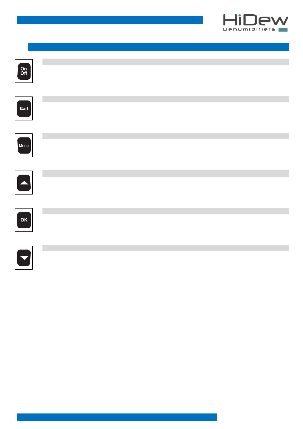
3.1 KEYBOARD
ON-OFF KEY
- on the main screen it allows the turning off of the unit
- on the ‘OFF’ screen it allows the turning on of the unit
EXIT KEY
- it allows the exit and the coming back to the main screen
- if you are modifying a value, it allows to exit from the modification
- on the main screen, pushing it for 4 seconds, it allows to display the software version
MENU KEY
- on the main screen, it allows to enter the first screen of the ‘user menu’
- on the time-bands programming screens, it allows to modify the day you are programming
UP KEY
- it allows to scroll through the screens or to modify a value
OK KEY
- it allows the execution of what is indicated on the display
DOWN KEY
- it allows to scroll through the screens or to modify a value

Rev 03 –Installation, use and maintenance manual
CCV - CCA - CCW –Air conditioner for cellars
16 - 48
3.2 MAIN SCREEN
USE OF KEYS
-With the OFF key you turn off the unit
-Keeping pushed the EXIT key, you display the software version
-With the MENU key, you enter the user menu
-indicates the day
-19:05 on the right top indicates the time
-23°C indicates the temperature
-70% indicates the humidity
-indicates that the heating is active
-indicates that the cooling is active
-indicates that the dehumidification is active
-indicates that the humidification is active
-indicates that the time-bands are active
-indicates that the unit is managed by a serial Modbus
-indicates that the unit is doing the defrosting
3.3 USER MENU
The user menu is composed by 9 easy-to-use screens, for the basic configurations of the unit:
1. Unit driver: manual or by time-bands *
2. Desired humidity setting *
3. Desired temperature setting *
4. Alarms management *
5. Time-bands programming *
6. Language setting
7. Day and time setting
8. Unit status display
9. Password request
* screen not always present
Each screen has a number on the right part, in order to simplify the use.
USE OF KEYS
-With UP and DOWN keys, you can run through the screens (some of them are not always
present)
-With EXIT key, you exit and come back to the main screen
-With OK key, you execute the function indicated on the screen

Rev 03 –Installation, use and maintenance manual
CCV - CCA - CCW –Air conditioner for cellars
17 - 48
On the left you find the screen 1 of the user menu, which allows to set the functioning of the
unit: MANUAL or on TIME BANDS
(this screen does not appear if: the unit is managed from a serial Modbus)
-press OK to enter in the modification phase
-press UP and DOWN to modify and with OK you confirm and exit from the modification phase
-press EXIT to exit and come back to the main screen
-press DOWN to shift to the following screen
On the left you find the screen 2 of the user menu, which allows to set the desired temperature
(this screen does not appear if: the unit is managed from a serial Modbus or is set on time bands)
-press OK to enter the modification phase
-press UP and DOWN to modify and with OK you confirm and exit from the modification phase
-press EXIT to exit and come back to the main screen
-press UP to come back to the previous screen
-press DOWN to shift to the following screen
On the left you find the screen 3 of the user menu, which allows to set the desired humidity
(this screen does not appear if: the unit is managed from a serial Modbus or is set on time bands)
-press OK to enter the modification phase
-press UP and DOWN to modify and with OK you confirm and exit from the modification phase
-press EXIT to exit and come back to the main screen
-press UP to come back to the previous screen
-press DOWN to shift to the following screen
On the left you find the screen 4 of the user menu, which allows to manage the alarms
(this screen only appears if: there are alarms present)
-press OK to enter the alarm menu
-press EXIT to exit and come back to the main screen
-press UP to come back to the previous screen
-press DOWN to shift to the following screen
On the left you find the screen 5 of the user menu, which allows to program the time-bands
(this screen does not appear if: the unit is managed from a serial Modbus or it is set in manual
mode)
-press OK to enter the time-bands menu
-press EXIT to exit and come back to the main screen
-press UP to come back to the previous screen
-press DOWN to shift to the following screen

Rev 03 –Installation, use and maintenance manual
CCV - CCA - CCW –Air conditioner for cellars
18 - 48
On the left you find the screen 6 of the user menu, which allows the setting of the language
-press OK to enter the modification phase
-press UP and DOWN to modify and with OK you confirm and exit from the modification phase
-press EXIT to exit and come back to the main screen
-press UP to come back to the previous screen
-press DOWN to shift to the following screen
On the left you find the screen 7 of the user menu, which allows to set the time and date,
necessary for the correct functioning of time-bands and other functions of the unit
You will modify:
1. the day of the week
2. the hour
3. the minutes
4. the day
5. the month
6. the year
-press OK to enter the modification phase
-press UP and DOWN to modify the set
-press OK to confirm and go to the following modification
-arrived at the last modification, with OK you confirm and exit from the modification phase
-press EXIT to exit and come back to the main screen
-press UP to come back to the previous screen
-press DOWN to shift to the following screen
On the left you find the screen 8 of the user menu, which allows to display the status of the unit,
that is to say what is turned on and what is turned off, plus the reading of the temperature and
humidity probes
-press OK to enter the unit status menu
-press EXIT to exit and come back to the main screen
-press UP to come back to the previous screen
-press DOWN to shift the following screen
On the left you find the screen 9 of the user menu, which allows to modify the parameters
covered by password
-press OK to enter the screen of password request
-press EXIT to exit and come back to the main screen
-press UP to come back to the previous screen

Rev 03 –Installation, use and maintenance manual
CCV - CCA - CCW –Air conditioner for cellars
19 - 48
3.4 ALARMS MENU
This menu is accessible only if there is an alarm on the unit and it allows to display the active alarm and, if possible, to reset it.
On the left you see the screen which allows to choose whether to display the alarm or to reset it.
-press EXIT to exit and come back to the main screen
-press UP and DOWN to select what to do
-press OK to confirm the choice and to shift to the further screen
On the left you see an example of alarm display; in the low part you see the equipment in alarm
or the type of alarm; in this example, electrical heaters are in alarm.
This screen is compulsory for the assistance in case of alarms
-press EXIT to exit and come back to the main screen
On the left you see the screen to reset the alarms. Only some alarms can be inactivated and you
can proceed by paying attention to the fact that the cause of the alarm has not been solved and
the alarm could appear again.
3.5 UNIT STATUS MENU
This menu is always accessible and allows to display all the information regarding the unit status, specifically the following lines:
recirculation fan, condensing fan, compressor, electrical heaters, humidifier, ambient temperature, ambient humidity, defrost
temperature, evaporation temperature, condensing pressure, cooling, dehumidification, heating and humidification.
The water valve and the electrical heaters are options so they could also be absent: in this case, on the corresponding line, some
strokes may appear.
On the left you see the unit status screen; in this case we see that the recirculation fan is
functioning at 50%, the condensing fan is not working, the compressor is off and the electrical
heater is not present.
.
-Press UP and DOWN to see the other lines
-Press EXIT to exit and come back to the main screen
-Pressing OK for 3 seconds the alarm is reset and you come back to the main screen
-Press EXIT to exit and come back to the alarm menu
Rev 03 –Installation, use and maintenance manual
CCV - CCA - CCW –Air conditioner for cellars
20 - 48
3.6 TIME-BANDS MENU
You can access this menu only if the unit is set in time-bands and it allows to program the bands which manage the on/off, the
humidity and the temperature.
It is fundamental to set correct date and time, go to the screen 7 of the User Menu (additional
information in the previous chapters)
The default values set are:
-Unit always turned on (24 h / day and 7 days / week)
-Desired temperature set all the days:
o26°C dalle 08:00 alle 20:00
o23°C dalle 20:00 alle 08:00
-Desired humidity always ta 60% (24 h / day and 7 days / week)
You can set different parameters for each hour of the day and for each day of the week.
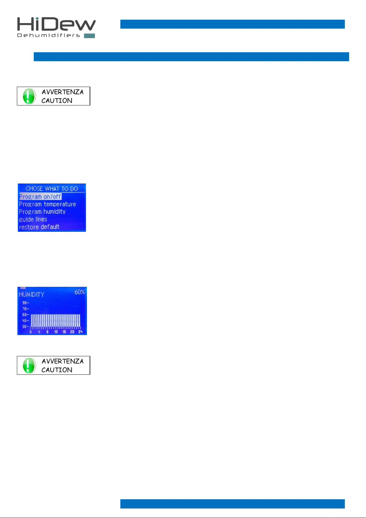
On the left you see the screen which allows to choose what to do:
-press EXIT to exit and come back to the main screen
-press UP and DOWN to select what to do
-press OK to confirm the choice and access to the dedicated screen indicated below
3.6.1 ON/OFF PROGRAM –HUMIDITY PROGRAM –TEMPERATURE PROGRAM
Selecting a program, you access to the programming screen; here below you find how to program the humidity:
-Once entered, the first bar will flash from 00.00 to 01.00; also the set value will flash on the
right top
-On the left top you have the rectangle which indicates the day we are programming
-Below the day rectangle, you find the indication of the topic you are programming: “HUMIDITY”
-Below there is the bar indicating the 24 hours
-On the left there is the bar indicating the desired humidity that can be set
KEYS’ USE:
-pressing OK you change the time to program
-pressing MENU you change the day to program
-pressing UP and DOWN you modify the programming of the flashing hour
-pressing EXIT you come back to the main screen
-keeping pressed OK and MENU, you copy the program of the active day to the following day
This manual suits for next models
2
Table of contents
Other HiDew Dehumidifier manuals


Popular Dehumidifier manuals by other brands


Innovative Dehumidifier
Innovative Dehumidifier WH120 Installation and operation manual

fisair
fisair DFRB-060-E Nstallation, operation and maintenance manual

Air Cleaning Equipment
Air Cleaning Equipment Horizon Titan XG90 Installation and operation manual

Sharp
Sharp DW-J27A Operation manual

Soleus Air
Soleus Air DS1-30-01B operating instructions

Colzer
Colzer PD123A user manual


