Coapt GEN2 User manual

© 2022 | Coapt, LLC | 303 W Institute Pl., Suite 200 | Chicago, IL 60610 | USA | 844.262.7800 | www.coaptengineering.com
HANDBOOK (V 4.0)
EVALUATION
KIT

HANDBOOK (V
4.0) GEN2 EVALUATION KIT
1
CONTENTS
CONTENTS..............................................................................................................................................................................................1
USER ASSISTANCE & SAFETY.........................................................................................................................................................3
USER ASSISTANCE ..................................................................................................................................................................................................................3
GENERAL WARNINGS AND PRECAUTIONS........................................................................................................................................................3
ADVERSE REACTIONS..........................................................................................................................................................................................................5
LABEL SYMBOL DESCRIPTIONS...................................................................................................................................................................................6
OVERVIEW ............................................................................................................................................................................................7
PURPOSE OF THE DEVICE................................................................................................................................................................................................7
INDICATIONS FOR USE........................................................................................................................................................................................................7
CONTRAINDICATIONS .........................................................................................................................................................................................................7
LIMITATIONS................................................................................................................................................................................................................................7
DESCRIPTION .............................................................................................................................................................................................................................7
DESCRIPTION OF THE DEVICE......................................................................................................................................................................................8
COMPATIBLE DEVICES........................................................................................................................................................................................................9
EMG Interface Cable Types .........................................................................................................................................................................................9
Electrode Contacts..........................................................................................................................................................................................................10
CONDITIONS FOR USE ....................................................................................................................................................................................................... 11
INSTRUCTIONS FOR USE ............................................................................................................................................................... 12
PATTERN RECOGNITION FUNDAMENTALS ...................................................................................................................................................... 12
PLANNING PATTERN RECOGNITION ELECTRODE LOCATIONS........................................................................................................ 13
Step 1: Discussing User Contractions................................................................................................................................................................. 13
Step 2: Palpating to find Underlying Muscle on the Residual Limb ........................................................................................... 13
Step 3: Planning Electrode Locations................................................................................................................................................................14
CHARGING THE BATTERY................................................................................................................................................................................................16
POWERING ON........................................................................................................................................................................................................................17
CONNECTING AN EMG INTERFACE CABLE.......................................................................................................................................................17
BLUETOOTH CONNECTION...........................................................................................................................................................................................18
TROUBLESHOOTING...........................................................................................................................................................................................................18
GUIDANCE FOR USERS................................................................................................................................................................... 19
PATTERN RECOGNITION CALIBRATION ..............................................................................................................................................................19
Calibrating All Motions in a Sequence..............................................................................................................................................................19
Calibrating Individual Motions................................................................................................................................................................................ 21
ADDITIONAL CALIBRATION TOOLS........................................................................................................................................................................ 22
Undoing Last Calibration........................................................................................................................................................................................... 22
Clearing/Resetting All Calibrated Motions ................................................................................................................................................... 23
Clearing/Resetting Individual Motions............................................................................................................................................................24
Calibration Restore Points ........................................................................................................................................................................................ 25
CONTROL COACH®..............................................................................................................................................................................................................26
ADAPTIVE ADVANCE®.......................................................................................................................................................................................................26
CALIBRATION BUTTON UNIT: SOUNDS & LED COLOR MEANINGS................................................................................................ 27

HANDBOOK (V
4.0) GEN2 EVALUATION KIT
2
CONTROL COMAPNION AND COMPLETE CONTROLROOM USER APPS................................................................... 29
INSTALLATION.........................................................................................................................................................................................................................29
CORE APP USES ....................................................................................................................................................................................................................29
Configuration .....................................................................................................................................................................................................................29
Input Validation ................................................................................................................................................................................................................30
EMG Pattern Exploration...........................................................................................................................................................................................30
Calibration.............................................................................................................................................................................................................................30
Practice and Games ......................................................................................................................................................................................................30
ADDITIONAL INFORMATION........................................................................................................................................................ 31
LIMITED US WARRANTY................................................................................................................................................................................................... 31
EXTENDED WARRANTY................................................................................................................................................................................................... 32
RETURNS..................................................................................................................................................................................................................................... 32
PRODUCT RETURN POLICY.......................................................................................................................................................................................... 32
INTELLECTUAL PROPERTY DISCLAIMER ........................................................................................................................................................... 32
TECHNICAL INFORMATION........................................................................................................................................................................................... 33
REGULATORY INFORMATION .....................................................................................................................................................................................34

HANDBOOK (V
4.0) GEN2 EVALUATION KIT
3
USER ASSISTANCE & SAFETY
USER ASSISTANCE
Contact your prosthetist if you have difficulty operating your device. You may also contact Coapt for support
(toll free) at 844-262-7800. Additional information about connecting and using the Evaluation Kit may be found
online at www.coaptengineering.com
GENERAL WARNINGS AND PRECAUTIONS
For safety and to prevent damage to the Evaluation Kit, please read and adhere to all safety precautions found
in this handbook. In addition, please follow the safety guidelines found in the user manual(s) for any connected
electrodes or prosthetic device(s). Failure to heed all warnings and precautions could cause damage to the
device and void the warranty. The following symbol definitions pertain to warnings in this handbook and on all
device labels.
SYMBOL DEFINITIONS
Warning regarding possible risk of severe accidents or injury.
Warning regarding possible risks of accident or injury.
Warning regarding possible damage to product or equipment.
Read and follow safety instructions. Read this entire manual before operating the Evaluation
Kit. Failure to do so could result in suboptimal system performance or injury, or damage to the
device.
NEVER attempt to remove or modify the battery in any way. Maintenance, repairs and
upgrades may only be performed by Coapt, LLC. Unauthorized device modification or
disassembly could cause damage to the device resulting in device malfunction, and injury to
the user.
NO modifying or disassembling device. Do not disassemble componentry or modify in any
way. Maintenance, repairs and upgrades may only be performed by Coapt, LLC. Unauthorized
device modification or disassembly could cause damage to the device resulting in device
malfunction, and injury to the user.
Use with implanted electronic devices. Do not bring the Evaluation Kit into the immediate
proximity of active implanted devices (e.g., pacemakers, defibrillators) unless assured by a
qualified healthcare professional that it is safe to do so. Interference between the Evaluation Kit
and the implanted device could cause the implanted device to malfunction.

HANDBOOK (V
4.0) GEN2 EVALUATION KIT
4
Use near open flame. Use care when operating device near an open flame, and do not allow
device to remain directly over an open flame. Direct exposure to an open flame may cause the
device to exceed safe temperature limits and may cause device malfunction.
Exposure to extreme temperatures. Do not expose to extreme low (<-20ºC) or high (>45ºC)
temperatures. Exposure to extreme temperatures could cause damage to the device and minor
injury.
Use near sources of high radio frequency (RF) energy. Use caution when operating the device
in proximity to sources of high RF energy (e.g., broadcast antennas or radar systems).
Interference could cause malfunctioning of the device.
Use in a corrosive environment. Do not expose the device to excessive amounts of corrosive
substances (e.g., salt water, sweat) or clean with acetone, benzene, or similar solution. Exposure
of electronics to cor
rosive substances can cause damage to the device resulting in device
malfunction, and minor injury to the user.
Exposure to excessive moisture, vibration, dust, or shock. Do not expose to excessive
moisture, liquid, dust, vibration, or shock. Doing so can cause damage to the device resulting in
device malfunction, and minor injury to the user.
Crushing of device. Take care not to allow the device to become smashed or crushed. Crushing
of the device can cause device malfunction, and minor injury to the user.
Use in areas of large static buildup. Take care when operating the device in areas with large
amounts of electrostatic buildup (e.g., very low humidity). Exposure to electrostatic discharge
can cause damage to the device resulting in device malfunction, and minor injury to the user.
Opening enclosures. Never open the Evaluation Kit enclosure. Opening the enclosure could
cause permanent damage to the Evaluation Kit resulting in device malfunction and minor
injury to the user.
Use of heat guns. Do not bring a heat gun or other heating device into proximity to the
Evaluation Kit. Overheating can cause damage to the Evaluation Kit
, resulting in device
malfunction and minor injury to the user.
Use with incorrect or incompatible electrodes. Make sure the Evaluation Kit is only
connected to an EMG Interface Cable referenced in this instruction manual. Use with an EMG
input that is incompatible with the system, may cause damage to and/or malfunction of the
device and could result in minor injury to the user.

HANDBOOK (V
4.0) GEN2 EVALUATION KIT
5
ADVERSE REACTIONS
MedWatch is the Food and Drug Administration's (FDA) program for reporting serious reactions, product
quality problems, therapeutic inequivalence/failure, and product use errors with human medical products,
including drugs, biologic products, medical devices, dietary supplements, infant formula, and cosmetics.
If you think you or someone in your family has experienced a serious reaction to a medical product, you are
encouraged to take the reporting form to your doctor. Your healthcare provider can provide clinical
information based on your medical record that can help FDA evaluate your report.
However, we understand that for a variety of reasons, you may not wish to have the form filled out by
your health care provider, or your health care provider may choose not to complete the form. Your
health care provider is NOT required to report to the FDA. In these situations, you may complete the
Online Reporting Form yourself.
You will receive an acknowledgement from FDA when your report is received. Reports are reviewed by FDA
staff. You will be personally contacted only if we need additional information.
SUBMITTING ADVERSE EVENT REPORTS TO FDA
Use one of the methods below to submit voluntary adverse event reports to the FDA:
•Report Online at www.accessdata.fda.gov/scripts/medwatch/index.cfm?action=reporting.home
•Consumer Reporting Form FDA 3500B. Follow the instructions on the form to either fax or mail it in for
submission. For help filling out the form, see MedWatchLearn. The form is available at
www.fda.gov/downloads/aboutFDA/reportsmanualsforms/forms/ucm349464.pdf
•Call FDA at 1-800-FDA-1088 to report by telephone
•Reporting Form FDA 3500 commonly used by health professionals. The form is available at
https://www.fda.gov/safety/medical-product-safety-information/medwatch-forms-fda-safety-reporting
SUBMITTING ADVERSE EVENT REPORTS IN THE EU
If you or someone in your family has experienced a serious adverse event, you are encouraged to report this
event to Coapt and/or the national competent authority of the country in which the event occurred. Serious
adverse events are defined as: any incident that led to or may lead to a death, serious deterioration of health, or
public health threat. You must report the event as soon as possible. Please contact Coapt if you have any
questions or need assistance.
HANDBOOK (V
4.0) GEN2 EVALUATION KIT
6
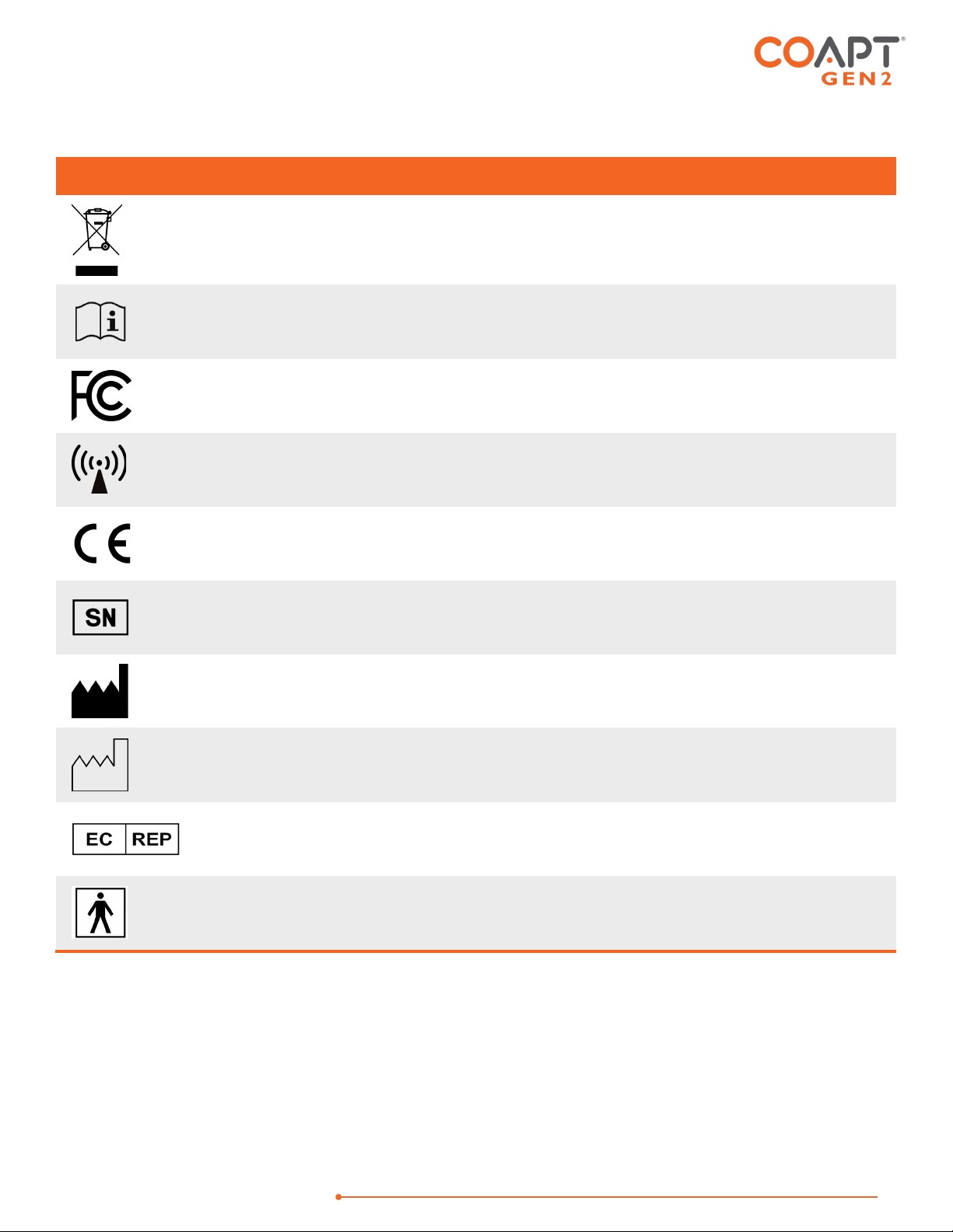
LABEL SYMBOL DESCRIPTIONS
SYMBOL
INFORMATION
EXPLANATION
Waste Electrical and
Electronic Equipment
Directive Symbol
Electrical and electronic items should not be
disposed of in your dustbin or wheelie bin, but
should be recycled.
Consult Accompanying
Documents Symbol
Please read the entire instruction manual before
using the device.
FCC Symbol This device is certified with the United States
Federal Communications Commission.
Non-ionizing Radiation
Symbol
This device emits non-hazardous levels of non-
ionizing radiation.
CE Mark The device is certified with the European Union
under the Medical Device Directives (93/42/EEC).
Serial Number Signifies the identification information for the
device.
Manufacturer Manufacturer Name and Address
Date of Manufacture Date the device was assembled at Coapt.
European Representative Signifies the European Representative for Coapt.
Type BF Applied Part The device has conductive contact with the
patient.

HANDBOOK (V
4.0) GEN2 EVALUATION KIT
7
OVERVIEW
PURPOSE OF THE DEVICE
The Coapt Evaluation Kit is intended to be used for the planning and/or practice phases of an upper limb
myoelectric prosthesis fitting with two main purposes:
1. The Evaluation Kit allows potential upper limb prosthesis users to “test drive” Coapt COMPLETE
CONTROL myoelectric pattern recognition technology. It permits visualization of EMG control signals
and enables control of a virtual prosthetic arm in real time using the COMPLETE CONTROLROOM Gen2
user interface application. The Evaluation Kit can also be used as a training tool to assist users in
enhancing their function with pattern recognition myoelectric control.
2. The Evaluation Kit assists with determining location of electrodes in the socket by allowing the clinician
to validate potential for pattern recognition myoelectric control. This enables efficient planning of the
prosthesis socket. With less time spent in the clinic searching for the best muscle control sites, more time
will be available for in-clinic functional practice.
INDICATIONS FOR USE
The Coapt Evaluation Kit is an accessory tool intended to be used during the planning and alignment of
myoelectric control contact locations for an upper limb prosthetic socket.
CONTRAINDICATIONS
None known.
LIMITATIONS
Careful evaluation is required to determine if individuals with brachial plexopathy or high-level amputations
without targeted muscle reinnervation surgery could benefit from the Coapt Complete Control System Gen2
The Coapt Evaluation Kit can aid in determining this.
DESCRIPTION
The Coapt Evaluation Kit is a handheld clinical tool created with technology from the Coapt Complete Control
System Gen2 using pattern recognition technology to revolutionize the way muscles’ bioelectrical activity
(electromyogram, EMG) signals are analyzed, recorded, and used for the control of upper limb prostheses.
The Evaluation Kit allows for visualization and evaluation of myoelectric signals generated from muscle
contractions. The Evaluation Kit permits virtual practice and training for pattern recognition myoelectric control.
HANDBOOK (V
4.0) GEN2 EVALUATION KIT
8
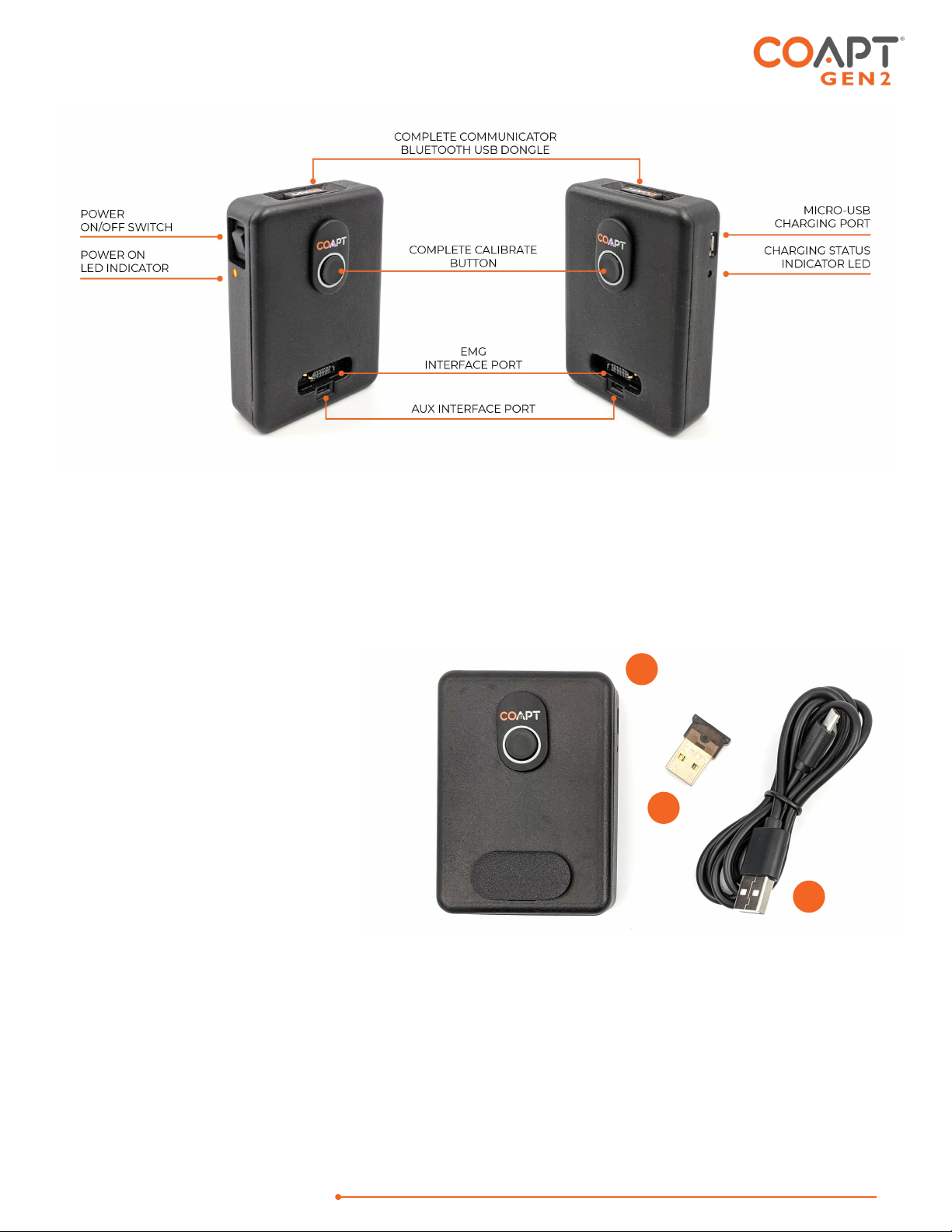
DESCRIPTION OF THE DEVICE
The Coapt Evaluation kit is to be used in conjunction with a Coapt EMG Interface Cable (sold separately) and
either Coapt’s Control Companion mobile app or Complete ControlRoom software app.
COMPONENTS
1. Evaluation Kit main unit
2. Complete Communicator USB
Bluetooth Dongle
3. USB Charging Cable – micro-
USB cable for main unit
charging via a USB port or USB
IEC 62133 certified external wall
plug (wall plug not provided by
Coapt)
ACCESSORIES
4. EMG Interface Cable(s) (sold separately)
5. Electrodes Contacts (if necessary, sold separately)
1
2
3

HANDBOOK (V
4.0) GEN2 EVALUATION KIT
9
COMPATIBLE DEVICES
EMG Interface Cable Types
When purchasing an Evaluation Kit, the EMG Interface Cable(s) are not included and must be ordered
separately. The Evaluation Kit is only compatible with Coapt EMG Interface Cable types shown in the table
below. Please contact a Coapt representative with any questions about EMG Interface Cable types and uses.
EMG INTERFACE
DESCRIPTION
Standard Eyelets EMG Interface
Cable
17 ring/eyelet terminations for use with a set of non-filtering, passive
electrode contacts (see below)
Snap Style EMG Interface Cable
17 snap terminations for use with with disposable, Temporary
Evaluation Electrode “Stickers” (see below)

HANDBOOK (V
4.0) GEN2 EVALUATION KIT
10
Evaluation-Style Cuff EMG
Interface Cable
Wrap-around, Velcro cuff for evaluation use with transradial and
small circumference transhumeral limbs
Osseointegration-Style Cuff
EMG Interface Cable
Elastic cuff for definitive Osseointegration use only
Electrode Contacts
The Evaluation Kit is designed to work with non-filtering, passive electrode contacts. Coapt recommends using
these compatible electrode contacts:
COMPATIBLE ELECTRODE CONTACTS
PART NUMBER(S)
FDA 510(K)
Coapt ControlSealTM Electrodes ELSB, ELSC, ELSD K223605
Coapt
Dome Electrodes
ELSA K190416
Coapt Evaluation Electrode “Stickers” ELEV K864690
Contact a Coapt representative when using electrode contacts from other manufacturers.
Skin irritation. Use of non-biocompatible materials (or materials to which the user is allergic)
for electrode contacts may cause skin rash or skin irritation. Ensure electrode contacts are
made of biocompatible material and do not cause an allergic reaction.

HANDBOOK (V
4.0) GEN2 EVALUATION KIT
11
CONDITIONS FOR USE
The Evaluation Kit was developed for clinical use and must not be used for unusual activities.
The Coapt Evaluation Kit should only be used by a trained and licensed medial professional or under supervision
of a trained and licensed medical professional.
See General Warnings and Precautions for more information regarding acceptable use conditions.

HANDBOOK (V
4.0) GEN2 EVALUATION KIT
12
INSTRUCTIONS FOR USE
PATTERN RECOGNITION FUNDAMENTALS
Muscle electrical (myoelectric) signals contain a lot of information. Pattern recognition uses the combined
information gathered from an array of electrode contacts to control multiple prosthesis movements intuitively.
Electrode Contact: All electrode contacts must maintain good contact with the user’s skin for ideal pattern
recognition function.
Good Calibration: Pattern recognition performance depends on good calibration. Users must understand the
methods to provide good calibration.
Pattern Repeatability:Pattern recognition works best if the user can replicate the patterns of muscle signals
for each motion the same way each time. Each motion should “feel” the same each time the user performs it.
Pattern Differentiation:Pattern recognition requires the pattern of muscle signals to be different for each
distinct motion. Each motion should “feel” different from all other motions.
Guidance for Learning and Practice:
•No need for extra-hard muscle contractions. Contraction levels should be moderate – like the feeling in
the strength of a comfortable handshake.
•Start slow and practice patience. This new pattern recognition method of control can take a little time
and practice to get used to.
•Control is not position-based. Example: if a hand is commanded to close (and it does) and the user then
wishes to turn the wrist, there’s no need to “hold” the hand closed while rotating the wrist, as each motion
is a separate activity.
•If control becomes erratic, reflect on the “feeling” of the motions when calibrated. The system does not
forget the patterns it was calibrated with, so it can always be helpful to return to those perceptions when
needed.
For more on myoelectric pattern recognition, please visit: https://coaptengineering.com/pattern-recognition

HANDBOOK (V
4.0) GEN2 EVALUATION KIT
13
PLANNING PATTERN RECOGNITION ELECTRODE LOCATIONS
Successful pattern recognition use depends on good muscle signal (myoelectric) information. The more
myoelectric information the pattern recognition algorithms get, the better the functional control potential.
The goal of planning and placing electrode contacts for pattern recognition is to spread electrode
contacts out as much as possible to capture all underlying muscle tissue that is providing information. An
analogy to this is planning the camera locations at a professional sports event – strategic locations are needed
to capture all angles and information from the area of interest.
Contact a
Coapt representative with any questions about myotesting and/or electrode
placement. Coapt is willing and able to assist with placement instruction and suggestion
—
these can often be accomplished by submitting socket and/or limb shape images to Coapt.
Step 1: Discussing User Contractions
Having a user explore all of the possible muscle contractions they can imagine, feel, and produce – even if some
contractions are faint and even contractions that might not be used for prosthesis control – is the important
first step in determining where their underlying muscle information “areas of interest” are.
A thorough discussion will have them think about and try all possible residual limb contractions. Ask the user
to first try contractions they would want to use for controlling their specific prosthesis functions. Focus on
contractions that are distinct and repeatable.
•Allow or encourage the user to mirror their perceived motions with their sound limb
as needed.
•When users have difficulty making contractions exactly matching a function (such as
not feeling all fingers well enough to mimic a certain grip, or not feeling their wrist
turning), explore supplemental contraction variations (for example: adding a feeling
of thumb extension to help with wrist supination, a feeling of pinky extension for wrist
pronation, or a feeling of fingers spreading for hand open).
•Be patient, listen, and take considerable time with this process.
•Perform this discussion in a relaxed environment.
•Develop a common vocabulary for specific motions.
Step 2: Palpating to find Underlying Muscle on the Residual Limb
To clinically determine where a user’s muscle information “areas of interest” are, have the user repeat all the
contractions from Step 1 while holding and feeling as much of their residual limb as possible. Ask the user to
sustain each muscle contraction for 3-4 seconds at a medium strength. Take time with this process. Be sure to
explore various contractions and repeat as necessary to feel all of the limb.

HANDBOOK (V
4.0) GEN2 EVALUATION KIT
14
While feeling the limb, take note of all areas where underlying muscle activity is felt, even if it is subtle. This will
guide where electrode contacts should be placed. Consider taking notes, capturing images, or making
temporary markings on the user’s skin.
•Feel for the overall muscle activity – like what the pattern recognition algorithm does
– by sensing the patterns of activity at multiple areas simultaneously.
•Remember: Pattern recognition myoelectric control does not rely on isolated muscle
signals, and it does not always need strong muscle signals. Avoid tendencies to only
feel with fingertips and to only feel for isolated “hotspots.
•Do not ignore areas of slight/subtle/weak underlying muscle contraction.
•Note any unique or unexpected areas of underlying muscle contraction – for
transhumeral amputees, this may mean unique muscle activity distal on the residual
limb.
•If the user contracts muscles quite hard for all motions, ask them to make
contractions a little more softly.
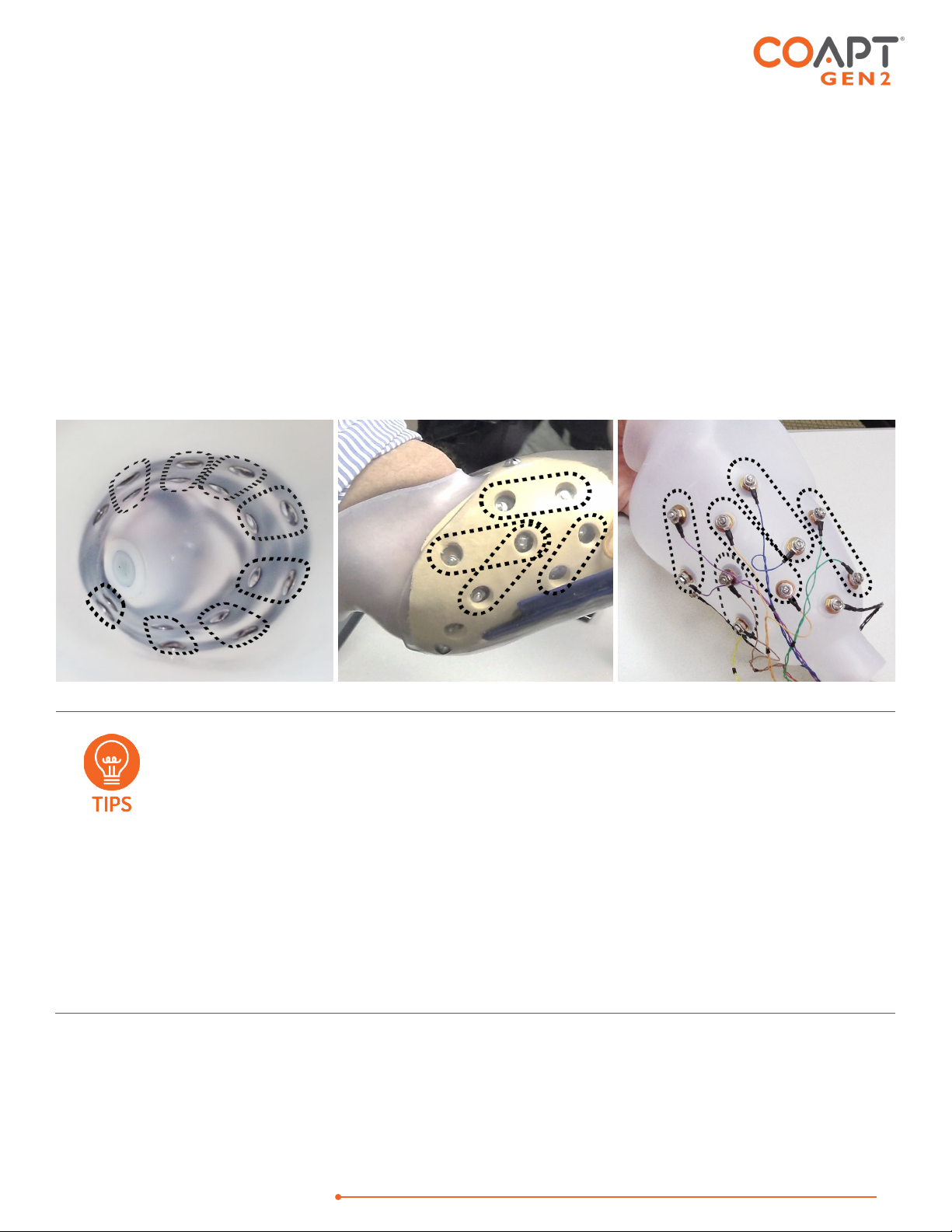
Step 3: Planning Electrode Locations
PLACING THE STANDARD EYELETS OR SNAPS EMG INTERFACE CABLE:
Use the areas of underlying muscle information discovered in Steps 1 and 2 to plan electrode contact locations.
The Standard Eyelets or Snaps EMG Interface cable has 17 electrode contacts to place, where 1 is an
independent reference “ground” contact and the remaining 16 are paired to make 8 “signal channels”. Each
pair of signal electrode contacts work together to capture the bi-polar, differential measurement of the muscle
contraction underlying their location. The two contacts for a given channel are ideally placed 30-60mm apart
and detect a myoelectric signal from an oval area encompassing their general location. The farther apart the
pair of electrode contacts, the larger (and deeper) the sensed area will be, and vice versa.
General Placement - Plan to place the 8 sets of 2 signal electrode contacts so their 8 myoelectric detection
“oval areas” fully capture all underlying muscle information. The independent reference contact (the 17th) should
HANDBOOK (V
4.0) GEN2 EVALUATION KIT
15
be positioned in a location that maintains excellent electrode-skin contact and should NOT be shared or paired
with any of the signal contacts.
Contact-Pair Orientation – While it is generally a good idea to align a pair of signal contacts in the direction of
underlying muscle fiber direction, it is ok with pattern recognition to place some of the electrode pairs “off-axis”.
This is helpful when fitting a residual limb with unique areas of muscle tissue, and for geometrically unique and
congenital limb presentations.
Contact Sharing – For a limb that is too small to reliably fit all 17 electrode contacts, it is ok to have a few of the
signal channels share an electrode contact. See the Coapt ControlSealTM product handbook for assembly detail
when sharing. When connecting the Standard Eyelets EMG Interface cable to shared electrode contacts, do
NOT place the two wires for the same channel (same color) on the same electrode contact – this will result in
zero signal for that channel and not be helpful for pattern recognition performance. Also, do not leave any
conductor wires unconnected. That is, always place electrode contacts for all 8 myoelectric signal channels.
•Consider starting with sites that correspond to previous electrode locations when
retrofitting existing myoelectric users.
•Do NOT limit electrode placement to “hotspot” areas.
•Identify locations to AVOID placing electrode contacts, such as
oAreas that will lose electrode-to-skin contact during use.
oAreas outside of socket boundaries or near valves.
oAreas that have no underlying muscle (i.e., bone only).
oSensitive skin areas.
oAreas over muscles that contract with arm loading positioning (example: deltoid or
brachioradialis muscles).
1
2
3
4
5
6
7
R
8
1
2
3
4
R
1
2
4
5
3
R

HANDBOOK (V
4.0) GEN2 EVALUATION KIT
16
PLACING THE EVALUATION-STYLE CUFF OR OSSEOINTEGRATION-STYLE CUFF EMG INTERFACE CABLE:
For best results, clean and dampen underlying skin areas
and secure the Evaluation-style cuff snugly around the
most muscular section of the limb being evaluated.
Specific rotational position is not crucial but consider
aligning the connection cable with the Ulna (below
elbow) or laterally (above elbow) for repeatability.
When using the Evaluation-style cuff, EMG channels will
share some electrode contact points, plus one contact for
system-wide reference/ground, making a total of 9
contact points.
CHARGING THE BATTERY
A micro-USB cable is provided with the Evaluation Kit for charging the internal battery of the main unit. To
charge the battery at any time, connect the USB 3.0 side of the cable to a USB computer port or suitable USB
wall-charging “brick” then connect the micro-USB side of the cable to the micro-USB port on the side of the
Evaluation Kit.
The Evaluation Kit requires 2.5-3 hours to fully charge from a fully depleted battery.
The Charging Status Indicator LED Light is next to the Evaluation Kit’s micro-USB port has three different colors:
CHARGING STATUS INDICATOR LED
STATUS
RED Low battery warning. Charge the Evaluation Kit.
AMBER Evaluation Kit is charging.
GREEN Evaluation Kit is fully charged.
HANDBOOK (V
4.0) GEN2 EVALUATION KIT
17
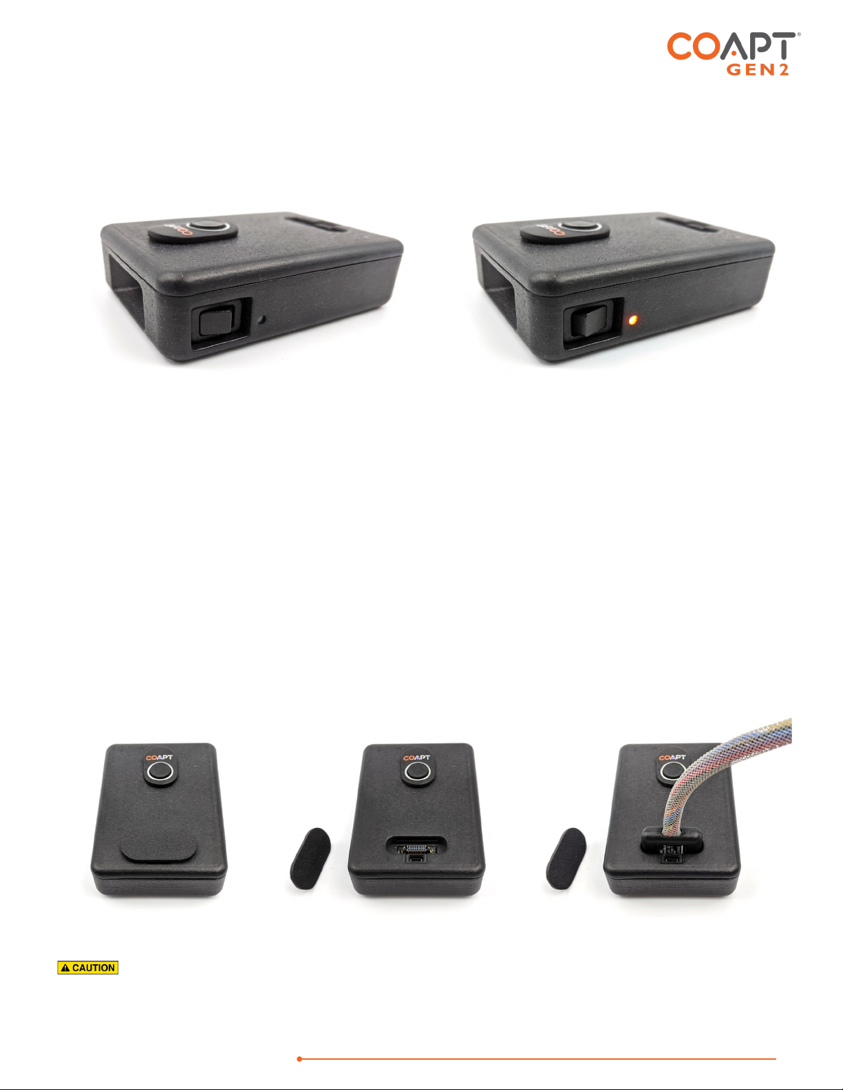
POWERING ON
To power on the Evaluation Kit, use the power switch located on the side of the main unit. The Power ON LED
light next to the power switch will illuminate orange and remain on when the Evaluation Kit is powered on.
When powered on, the LED light of the Complete Calibrate button on the top of the main unit may also be
illuminated. See below for information on Complete Calibrate button LED colors.
The Evaluation Kit will operate for approximately 6 hours from a full charge.
CONNECTING AN EMG INTERFACE CABLE
The Coapt Evaluation Kit will need to be connected to a compatible EMG Interface Cable (see Accessories
section) for proper operation. All EMG Interface Cable types have the same mating connector for attaching to
the Evaluation Kit. This connector mates firmly to the EMG Interface Port on the top of the Evaluation Kit.
1. Remove the black plastic EMG Interface Port cap.
2. Plug the connector end of the EMG Interface Cable to the EMG Interface Port with the label side of the
EMG Interface Cable connector facing away from the Complete Calibrate Button.
Do Not force improper connection. If the EMG Interface Cable connector is forced in the
wrong orientation, damage to the EMG Interface Cable and/or the Evaluation Kit could result.

HANDBOOK (V
4.0) GEN2 EVALUATION KIT
18
BLUETOOTH CONNECTION
The Coapt Evaluation Kit communicates to the Control Companion mobile app or Complete ControlRoom
software app via Bluetooth. To prepare this connection for a personal computer:
1. Remove the Complete Communicator USB Bluetooth Dongle from its holder pocket in the top edge
of the Evaluation Kit’s main unit.
2. Plug the Complete Communicator USB Bluetooth Dongle into a USB port on your personal computer.
TROUBLESHOOTING
Contact a Coapt representative for assistance as required if encountering situations out of the ordinary, not
covered in this product handbook, or not found via the online resources at www.coaptengineering.com
Contact Coapt toll free at 844-262-7800
Technical support is available at support@coaptengineering.com
Clinical support is available at clinical@coaptengineering.com
Engineering support is available at engineering@coaptengineering.com

HANDBOOK (V
4.0) GEN2 EVALUATION KIT
19
GUIDANCE FOR USERS
PATTERN RECOGNITION CALIBRATION
Calibration is how the Coapt system learns your muscle signals patterns – specifically, the patterns you will use
to personalize the control of your prosthesis. The better you calibrate, the easier it will be to control.
Calibration can be done at any time and typically requires less than two minutes. During calibration, you are
guided (either by auto-movements of your prosthesis or instructions on a screen) to hold muscle contractions
corresponding to the motions of your prosthesis. As you hold these contractions, the Coapt system listens and
learns the signals, computing a “pattern recognition” memory of what your muscle contractions look like. After
calibration, the Coapt system uses these memories to determine how you are controlling your prosthesis.
•Make sure the muscle contractions you control the prosthesis with feel like the
contractions you calibrated with.
•Make sure contractions for different actions feel different from each other.
•
Make sure contractions for the same action are consistent.
If the LED on the Complete Calibrate
button is blinking white after any calibration, there are
helpful calibration improvement messages available in the Control Coach®
tool of the
Complete ControlRoom software app or Control Companion mobile app.
Calibrating All Motions in a Sequence
This is a method to provide muscle signals patterns (to compute the pattern recognition memory) for all of the
enabled motions of your virtual prosthesis in an organized sequence.
USING THE PHYSICAL BUTTON
Hold the Coapt Complete Calibrate button for 2 seconds and release it once you hear the beep
to start the calibration sequence.
The virtual prosthesis moves itself through a sequence of motions and you follow along with
your corresponding muscle contractions. For example, if the virtual wrist is rotating palm up,
hold your intended muscle contraction for wrist supination. If the virtual hand is opening, hold
your muscle contraction for hand open. If the virtual prosthesis pauses for a moment, be sure
to relax your muscle contractions. As you hold and relax muscle contractions corresponding
to the prosthesis motions, the system is learning and adapting its pattern recognition memory.
Other manuals for GEN2
3
Table of contents
Other Coapt Motherboard manuals


