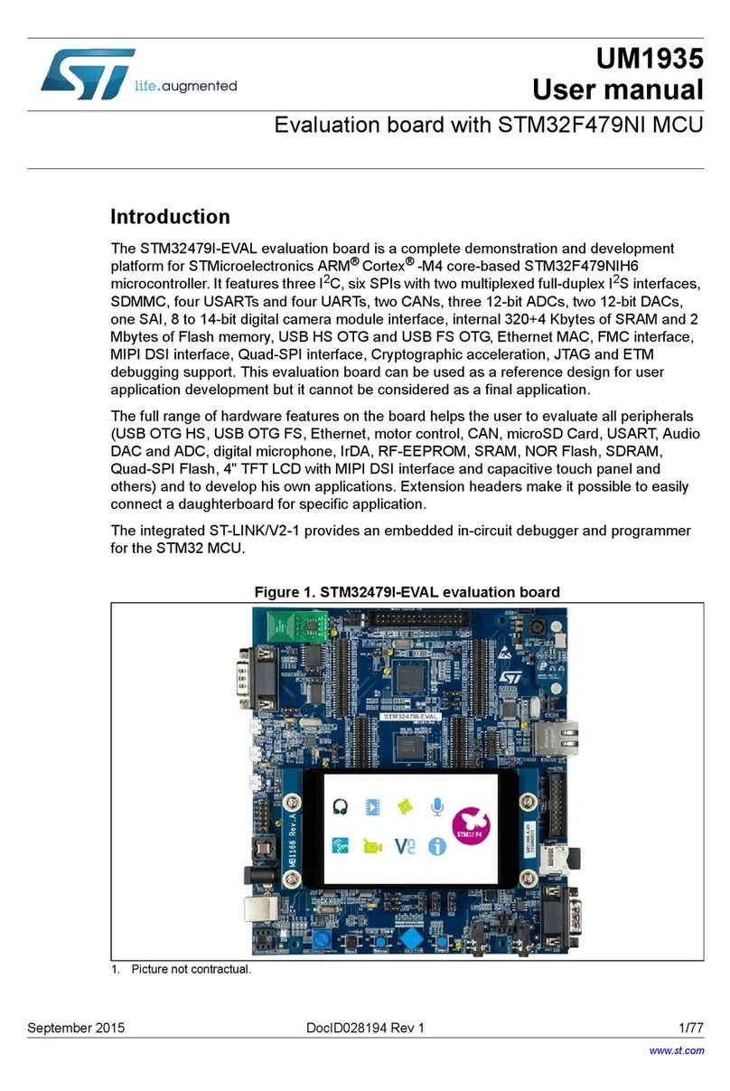
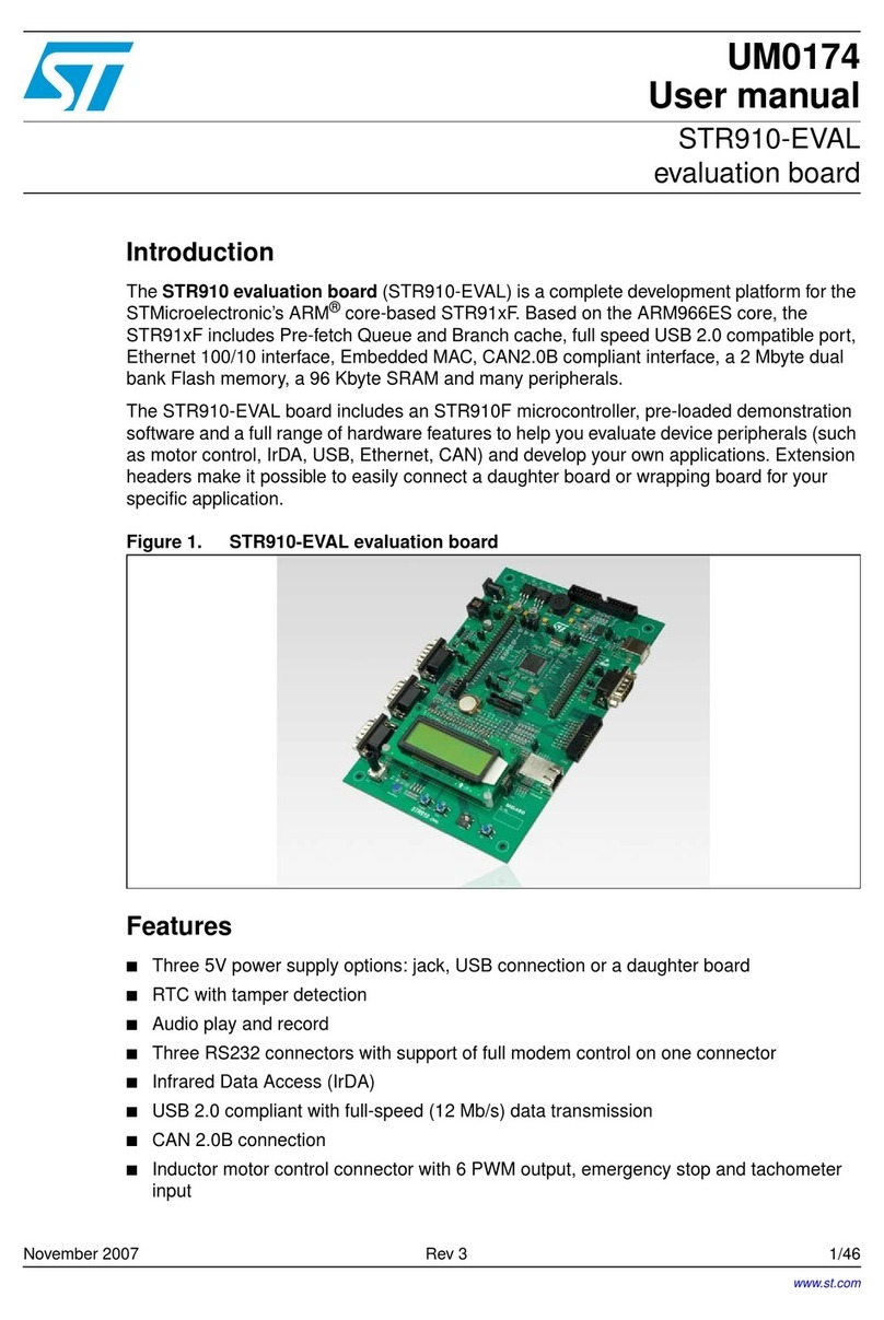
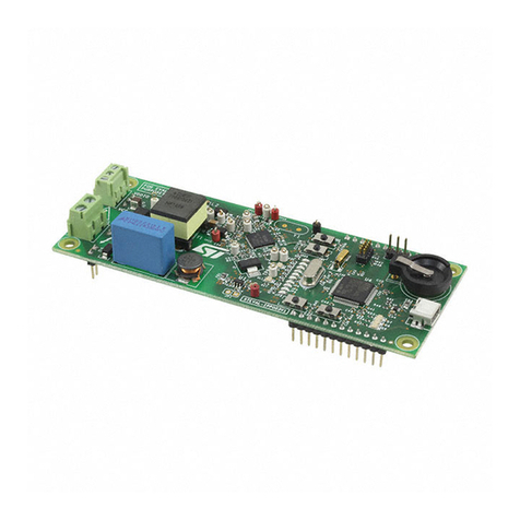
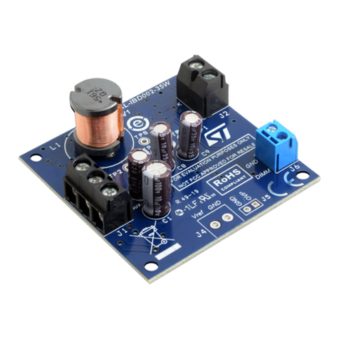
ST STM32 Nucleo-32 User manual

November 2018 UM1956 Rev 5 1/37
1
UM1956
User manual
STM32 Nucleo-32 boards (MB1180)
Introduction
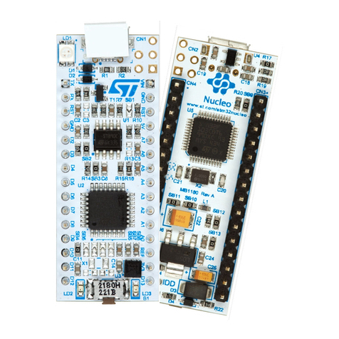
The STM32 Nucleo-32 boards based on the MB1180 reference board (NUCLEO-F031K6,
NUCLEO-F042K6, NUCLEO-F301K8, NUCLEO-F303K8, NUCLEO-L011K4, NUCLEO-
L031K6, NUCLEO-L412KB, NUCLEO-L432KC) provide an affordable and flexible way for
users to try out new concepts and build prototypes with STM32 microcontrollers, choosing
from the various combinations of performance, power consumption and features. The
Arduino™ Nano connectivity support makes it easy to expand the functionality of the
Nucleo-32 open development platform with a wide choice of specialized shields. The
STM32 Nucleo-32 boards do not require any separate probe as they integrate the ST-
LINK/V2-1 debugger/programmer and come with the STM32 comprehensive software HAL
library, together with various packaged software examples, as well as direct access to the
Arm®Mbed™ online resources at http://mbed.org.
Figure 1. STM32 Nucleo-32 board
Picture is not contractual.
www.st.com

Contents UM1956
2/37 UM1956 Rev 5
Contents
1 Features . . . . . . . . . . . . . . . . . . . . . . . . . . . . . . . . . . . . . . . . . . . . . . . . . . . 6
2 Product marking . . . . . . . . . . . . . . . . . . . . . . . . . . . . . . . . . . . . . . . . . . . . 7
3 Ordering information . . . . . . . . . . . . . . . . . . . . . . . . . . . . . . . . . . . . . . . . 7
4 Conventions . . . . . . . . . . . . . . . . . . . . . . . . . . . . . . . . . . . . . . . . . . . . . . . . 8
5 Quick start . . . . . . . . . . . . . . . . . . . . . . . . . . . . . . . . . . . . . . . . . . . . . . . . . 9
5.1 Getting started . . . . . . . . . . . . . . . . . . . . . . . . . . . . . . . . . . . . . . . . . . . . . . 9
5.2 System requirements . . . . . . . . . . . . . . . . . . . . . . . . . . . . . . . . . . . . . . . . . 9
6 Hardware layout and configuration . . . . . . . . . . . . . . . . . . . . . . . . . . . . 10
6.1 STM32 Nucleo-32 board layout . . . . . . . . . . . . . . . . . . . . . . . . . . . . . . . . .11
6.2 STM32 Nucleo-32 board mechanical drawing . . . . . . . . . . . . . . . . . . . . . 13
6.3 Embedded ST-LINK/V2-1 . . . . . . . . . . . . . . . . . . . . . . . . . . . . . . . . . . . . . 14
6.3.1 Drivers . . . . . . . . . . . . . . . . . . . . . . . . . . . . . . . . . . . . . . . . . . . . . . . . . 14
6.3.2 ST-LINK/V2-1 firmware upgrade . . . . . . . . . . . . . . . . . . . . . . . . . . . . . . 15
6.4 Power supply and power selection . . . . . . . . . . . . . . . . . . . . . . . . . . . . . . 16
6.4.1 Power supply input from USB connector . . . . . . . . . . . . . . . . . . . . . . . . 16
6.4.2 External power supply inputs . . . . . . . . . . . . . . . . . . . . . . . . . . . . . . . . . 17
VIN or +5 V power supply. . . . . . . . . . . . . . . . . . . . . . . . . . . . . . . . . . . . . . . . . . .17
+3V3 power supply. . . . . . . . . . . . . . . . . . . . . . . . . . . . . . . . . . . . . . . . . . . . . . . .18
6.4.3 External power supply output . . . . . . . . . . . . . . . . . . . . . . . . . . . . . . . . 18
6.5 LEDs . . . . . . . . . . . . . . . . . . . . . . . . . . . . . . . . . . . . . . . . . . . . . . . . . . . . 18
6.6 Push-button . . . . . . . . . . . . . . . . . . . . . . . . . . . . . . . . . . . . . . . . . . . . . . . 18
6.7 JP1 (IDD) . . . . . . . . . . . . . . . . . . . . . . . . . . . . . . . . . . . . . . . . . . . . . . . . . 19
6.8 OSC clock . . . . . . . . . . . . . . . . . . . . . . . . . . . . . . . . . . . . . . . . . . . . . . . . 19
6.9 USART virtual communication . . . . . . . . . . . . . . . . . . . . . . . . . . . . . . . . . 20
6.10 Solder bridges . . . . . . . . . . . . . . . . . . . . . . . . . . . . . . . . . . . . . . . . . . . . . 20
6.11 Arduino Nano connectors . . . . . . . . . . . . . . . . . . . . . . . . . . . . . . . . . . . . . 21
7 Electrical schematics . . . . . . . . . . . . . . . . . . . . . . . . . . . . . . . . . . . . . . . 32
UM1956 Rev 5 3/37
UM1956 Contents
3
Appendix A Compliance statements. . . . . . . . . . . . . . . . . . . . . . . . . . . . . . . . . . . 35
A.1 Federal Communications Commission (FCC) and Industry
Canada (IC) Compliance Statements . . . . . . . . . . . . . . . . . . . . . . . . . . . . 35
A.1.1 FCC Compliance Statement . . . . . . . . . . . . . . . . . . . . . . . . . . . . . . . . . . 35
Part 15.1936 . . . . . . . . . . . . . . . . . . . . . . . . . . . . . . . . . . . . . . . . . . . . . . . . . . . . .35
Part 15.105 . . . . . . . . . . . . . . . . . . . . . . . . . . . . . . . . . . . . . . . . . . . . . . . . . . . . . .35
Part 15.21 . . . . . . . . . . . . . . . . . . . . . . . . . . . . . . . . . . . . . . . . . . . . . . . . . . . . . . .35
A.1.2 IC Compliance Statement . . . . . . . . . . . . . . . . . . . . . . . . . . . . . . . . . . . . 35
Compliance Statement . . . . . . . . . . . . . . . . . . . . . . . . . . . . . . . . . . . . . . . . . . . . .35
Déclaration de conformité. . . . . . . . . . . . . . . . . . . . . . . . . . . . . . . . . . . . . . . . . . .35
Revision history . . . . . . . . . . . . . . . . . . . . . . . . . . . . . . . . . . . . . . . . . . . . . . . . . . . . 36

List of tables UM1956
4/37 UM1956 Rev 5
List of tables
Table 1. Ordering information . . . . . . . . . . . . . . . . . . . . . . . . . . . . . . . . . . . . . . . . . . . . . . . . . . . . . . . 7
Table 2. Codification explanation . . . . . . . . . . . . . . . . . . . . . . . . . . . . . . . . . . . . . . . . . . . . . . . . . . . . 8
Table 3. ON/OFF conventions . . . . . . . . . . . . . . . . . . . . . . . . . . . . . . . . . . . . . . . . . . . . . . . . . . . . . . 8
Table 4. SB1 configuration . . . . . . . . . . . . . . . . . . . . . . . . . . . . . . . . . . . . . . . . . . . . . . . . . . . . . . . . 16
Table 5. External power sources . . . . . . . . . . . . . . . . . . . . . . . . . . . . . . . . . . . . . . . . . . . . . . . . . . . 17
Table 6. OSC clock configurations . . . . . . . . . . . . . . . . . . . . . . . . . . . . . . . . . . . . . . . . . . . . . . . . . . 19
Table 7. Virtual communication configuration. . . . . . . . . . . . . . . . . . . . . . . . . . . . . . . . . . . . . . . . . . 20
Table 8. Solder bridges. . . . . . . . . . . . . . . . . . . . . . . . . . . . . . . . . . . . . . . . . . . . . . . . . . . . . . . . . . . 20
Table 9. Arduino Nano connectors on NUCLEO-F031K6 . . . . . . . . . . . . . . . . . . . . . . . . . . . . . . . . 21
Table 10. Arduino Nano connectors on NUCLEO-F042K6 . . . . . . . . . . . . . . . . . . . . . . . . . . . . . . . . 23
Table 11. Arduino Nano connectors on NUCLEO-F301K8 . . . . . . . . . . . . . . . . . . . . . . . . . . . . . . . . 24
Table 12. Arduino Nano connectors on NUCLEO-F303K8 . . . . . . . . . . . . . . . . . . . . . . . . . . . . . . . . 25
Table 13. Arduino Nano connectors on NUCLEO-L011K4. . . . . . . . . . . . . . . . . . . . . . . . . . . . . . . . . 26
Table 14. Arduino Nano connectors on NUCLEO-L031K6. . . . . . . . . . . . . . . . . . . . . . . . . . . . . . . . . 27
Table 15. Arduino Nano connectors on NUCLEO-L412KB . . . . . . . . . . . . . . . . . . . . . . . . . . . . . . . . 28
Table 16. Arduino Nano connectors on NUCLEO-L432KC . . . . . . . . . . . . . . . . . . . . . . . . . . . . . . . . 29
Table 17. Document revision history . . . . . . . . . . . . . . . . . . . . . . . . . . . . . . . . . . . . . . . . . . . . . . . . . 36

UM1956 Rev 5 5/37
UM1956 List of figures
5
List of figures
Figure 1. STM32 Nucleo-32 board. . . . . . . . . . . . . . . . . . . . . . . . . . . . . . . . . . . . . . . . . . . . . . . . . . . . 1
Figure 2. Hardware block diagram. . . . . . . . . . . . . . . . . . . . . . . . . . . . . . . . . . . . . . . . . . . . . . . . . . . 10
Figure 3. STM32 Nucleo-32 board top layout . . . . . . . . . . . . . . . . . . . . . . . . . . . . . . . . . . . . . . . . . . 11
Figure 4. STM32 Nucleo-32 board bottom layout . . . . . . . . . . . . . . . . . . . . . . . . . . . . . . . . . . . . . . . 12
Figure 5. STM32 Nucleo-32 board mechanical drawing . . . . . . . . . . . . . . . . . . . . . . . . . . . . . . . . . . 13
Figure 6. USB composite device . . . . . . . . . . . . . . . . . . . . . . . . . . . . . . . . . . . . . . . . . . . . . . . . . . . . 14
Figure 7. NUCLEO-F031K6, NUCLEO-F042K6, NUCLEO-F303K8,
and NUCLEO-F301K8 pin assignment. . . . . . . . . . . . . . . . . . . . . . . . . . . . . . . . . . . . . . . . 30
Figure 8. NUCLEO-L011K4, NUCLEO-L031K6, NUCLEO-L412KB
and NUCLEO-L432KC pin assignment . . . . . . . . . . . . . . . . . . . . . . . . . . . . . . . . . . . . . . . 31
Figure 9. STM32 Nucleo-32 board (top view) . . . . . . . . . . . . . . . . . . . . . . . . . . . . . . . . . . . . . . . . . . 32
Figure 10. MCU . . . . . . . . . . . . . . . . . . . . . . . . . . . . . . . . . . . . . . . . . . . . . . . . . . . . . . . . . . . . . . . . . . 33
Figure 11. ST-LINK/V2-1 . . . . . . . . . . . . . . . . . . . . . . . . . . . . . . . . . . . . . . . . . . . . . . . . . . . . . . . . . . . 34

Features UM1956
6/37 UM1956 Rev 5
1 Features
•STM32 microcontrollers in 32-pin packages
•Three LEDs:
– USB communication LED (LD1)
– Power LED (LD2)
– User LED (LD3)
•Reset push-button
•Board expansion connector:
– Arduino™ Nano
•Flexible board power supply options:
– ST-LINK USB VBUS
– External sources
•On-board ST-LINK/V2-1 debugger/programmer with USB re-enumeration capability:
mass storage, Virtual COM port and debug port
•Support of a wide choice of Integrated Development Environments (IDEs) including
IAR™ EWARM(a), Keil®MDK-ARM(a), GCC-based IDEs, Arm®Mbed™(b), (c)
•Arm®Mbed Enabled™ compliant (only for some Nucleo part numbers)
a. On Windows®only.
b. Arm and Mbed are registered trademarks or trademarks of Arm Limited (or its subsidiaries) in the US and or
elsewhere.
c. Refer to the https://www.mbed.com website and to Table 1: Ordering information, to determine which Nucleo
board order codes are supported.

UM1956 Rev 5 7/37
UM1956 Product marking
36
2 Product marking
Evaluation tools marked as "ES" or "E" are not yet qualified and therefore they are not ready
to be used as reference design or in production. Any consequences arising from such usage
will not be at STMicroelectronics’ charge. In no event, will STMicroelectronics be liable for
any customer usage of these engineering sample tools as reference design or in production.
"E" or "ES" marking examples of location:
•On the targeted STM32 that is soldered on the board (for illustration of STM32 marking,
refer to the section Package information of the STM32 datasheet at www.st.com).
•Next to the evaluation tool ordering part number, that is stuck or silk-screen printed on
the board.
Some boards feature a specific STM32 device version, which allows the operation of any
bundled commercial stack/library available. This STM32 device shows a "U" marking option
at the end of the standard part number and is not available for sales.
In order to use the same commercial stack in his application, a developer may need to
purchase a part number specific to this stack/library. The price of those part numbers
includes the stack/library royalties.
3 Ordering information
To order the STM32 Nucleo-32 board, refer to Table 1.
Table 1. Ordering information
Order code Reference board Target STM32
NUCLEO-F031K6(1)
1. Arm®Mbed Enabled™.
MB1180
STM32F031K6T6
NUCLEO-F042K6(1) STM32F042K6T6
NUCLEO-F301K8 STM32F301K8T6
NUCLEO-F303K8(1) STM32F303K8T6
NUCLEO-L011K4(1) STM32L011K4T6
NUCLEO-L031K6(1) STM32L031K6T6
NUCLEO-L412KB STM32L412KBU6U(2)
2. Refer to Chapter 2: Product marking for details.
NUCLEO-L432KC(1) STM32L432KCU6U(2)

Conventions UM1956
8/37 UM1956 Rev 5
The meaning of the codification is explained in Table 2.
Table 2. Codification explanation
NUCLEO-TXXXKY Description Example: NUCLEO-L412KB
TXXX STM32 product line STM32L412
KSTM32 package pin count 32 pins
Y
STM32 Flash memory size:
– 4 for 16 Kbytes
– 6 for 32 Kbytes
– 8 for 64 Kbytes
–Bfor128Kbytes
–Cfor256Kbytes
128 Kbytes
The order code is mentioned on a sticker, placed on the top side of the board.
4 Conventions
Table 3 provides the conventions used for the ON and OFF settings in the present
document.
Table 3. ON/OFF conventions
Convention Definition
Jumper JPx ON Jumper fitted
Jumper JPx OFF Jumper not fitted
Solder bridge SBx ON SBx connections closed by solder or 0 ohm resistor
Solder bridge SBx OFF SBx connections left open
In this document the reference is “STM32 Nucleo-32 board” for all information that is
common to all sale types.

UM1956 Rev 5 9/37
UM1956 Quick start
36
5 Quick start
The STM32 Nucleo-32 board is a low-cost and easy-to-use development kit used to quickly
evaluate and start a development with an STM32 microcontroller in LQFP32 or UFQFPN32
package.
Before installing and using the product, accept the Evaluation Product License Agreement
that can be found at www.st.com/epla.
For more information on the STM32 Nucleo-32 board and to access the demonstration
software, visit the www.st.com/stm32nucleo webpage.
5.1 Getting started
Follow the sequence below, to configure the STM32 Nucleo-32 board and launch the
demonstration software:
•Check solder bridge position on the board, SB1 OFF, SB14 ON (internal regulator), JP1
ON (IDD) selected.
•For a correct identification of all device interfaces from the host PC and before
connecting the board, install the Nucleo USB driver, available at the
www.st.com/stm32nucleo webpage.
•To power the board connect the STM32 Nucleo-32 board to a PC through the USB
connector CN1 with a USB cable Type-A to Micro-B. The red LED LD2 (PWR) and LD1
(COM) light up and green LED LD3 blinks.
•Remove the jumper placed between D2 (CN3 pin 5) and GND (CN3 pin 4).
•Observe how the blinking frequency of the green LED LD3 changes, when the jumper
is in place or when it is removed.
•The demonstration software and several software examples on how to use the STM32
Nucleo-32 board features, are available at the www.st.com/stm32nucleo webpage.
•Develop an application using the available examples.
5.2 System requirements
•Windows®OS (7, 8 and 10), Linux®64-bit or macOS®(a)
•USB Type-A to Micro-B USB cable
a. macOS®is a trademark of Apple Inc. registered in the U.S. and other countries.

Hardware layout and configuration UM1956
10/37 UM1956 Rev 5
6 Hardware layout and configuration
The STM32 Nucleo-32 board is based on a 32-pin STM32 microcontroller in LQFP or
UFQFPN package.
Figure 2 illustrates the connections between the STM32 and its peripherals (ST-LINK/V2-1,
push-button, LED, and Arduino Nano connectors).
Figure 3: STM32 Nucleo-32 board top layout and Figure 4: STM32 Nucleo-32 board bottom
layout show the location of these connections on the STM32 Nucleo-32 board.
Figure 2.
06Y9
(PEHGGHG
67/,1.9
670
0LFURFRQWUROOHU
5(6(7
0LFUR
86%
,2 ,2
%
567
$UGXLQR1DQR
FRQQHFWRU
/('
/'
$UGXLQR1DQR
FRQQHFWRU
Hardware block diagram

UM1956 Rev 5 11/37
UM1956 Hardware layout and configuration
36
6.1 STM32 Nucleo-32 board layout
Figure 3.
U2
STM32
Microcontroller
CN1
ST-LINK Micro B
USB connector
LD1
(Red/Green LED)
COM
LD2
(
Red LED
)
Power
B1
Reset Button
LD3
(
Green LED
)
CN2
ST-LINK SWD
connector
(reserved)
SB1
Power confi
g
uration
SB2
Connect VCP TX to ST-LINK
SB3
Connect VCP RX to ST-LINK
SB4
Connect PF0/PC14 to MCO
SB6
Connect PF0/PC14 to D8
SB5
Co
nn
ect
PF
0/
P
C
14
to
X1
SB7
Connect PF1/PC15 to X1
SB8
Connect PF1/PC15 to D7
STM32 Nucleo-32 board top layout

Hardware layout and configuration UM1956
12/37 UM1956 Rev 5
Figure 4.
CN4
Arduino Nano connector
CN3
Arduino Nano connector
JP1
IDD m
easu
r
e
m
e
n
t
SB14
3.3V regulator output
SB18
Connect D4 to A4
SB16
Connect D5 to A5
SB11
Connect 670 pin 16 to
GND
SB15
Connect D13 to LD3
SB17
Connect MCO to PA0
SB10
Connect VDD to 670
pin 5
SB13
Connect GND to 670 pin
32
SB12
Connect BOOT0 to GND
SB9
ST-LINK RESET
STM32 Nucleo-32 board bottom layout

Hardware layout and configuration UM1956
14/37 UM1956 Rev 5
6.3 Embedded ST-LINK/V2-1
The ST-LINK/V2-1 programming and debugging tool is integrated in the STM32 Nucleo-32
board. The ST-LINK/V2-1 makes the STM32 Nucleo-32 board mbed enabled.
The embedded ST-LINK/V2-1 supports only the SWD for STM32 devices. For information
about debugging and programming features refer to: ST-LINK/V2 in-circuit
debugger/programmer for STM8 and STM32 User manual (UM1075), which describes in
detail all the ST-LINK/V2 features.
The new features supported by the ST-LINK/V2-1 comparing with ST-LINK/V2 are:
•USB software re-enumeration
•Virtual Com port interface on USB
•Mass storage interface on USB
•USB power management request for more than 100 mA power on USB
The features not supported on ST-LINK/V2-1 are:
•SWIM interface
•Minimum supported application voltage limited to 3 V
Known limitation:
•Activating the readout protection on the STM32 target, prevents the target application
from running afterwards. The target readout protection must be kept disabled on ST-
LINK/V2-1 boards.
The embedded ST-LINK/V2-1 is directly connected to the SWD port of the target STM32.
6.3.1 Drivers
The ST-LINK/V2-1 requires a dedicated USB driver, which, for Windows®7, 8 and 10, can
be found at www.st.com.
In case the STM32 Nucleo-32 board is connected to the PC before the driver is installed,
some Nucleo interfaces may be declared as “Unknown” in the PC device manager. In this
case the user must install the driver files (refer to Figure 6) and from the device manager
update the driver of the connected device.
Note: Prefer using the “USB Composite Device” handle for a full recovery.
Figure 6. USB composite device

UM1956 Rev 5 15/37
UM1956 Hardware layout and configuration
36
6.3.2 ST-LINK/V2-1 firmware upgrade
The ST-LINK/V2-1 embeds a firmware upgrade mechanism for in-situ upgrade through the
USB port. As the firmware may evolve during the lifetime of the ST-LINK/V2-1 product (for
example new functionalities added, bug fixes, support for new microcontroller families), it is
recommended to visit www.st.com before starting to use the STM32 Nucleo-32 board and
periodically, to stay up-to-date with the latest firmware version.

Hardware layout and configuration UM1956
16/37 UM1956 Rev 5
6.4 Power supply and power selection
The power supply is provided either by the host PC through the USB cable, or by an
external source: VIN (7 V-12 V), +5 V (5 V) or +3V3 power supply pins on CN4. In case VIN,
+5 V or +3V3 is used to power the STM32 Nucleo-32 board, this power source must comply
with the standard EN-60950-1: 2006+A11/2009, and must be Safety Extra Low Voltage
(SELV) with limited power capability.
In case the power supply is +3V3, the ST-LINK is not powered and cannot be used.
6.4.1 Power supply input from USB connector
The STM32 Nucleo-32 board and shield board can be powered from the ST-LINK USB
connector CN1. Note that only the ST-LINK part is power supplied before the USB
enumeration phase, as the host PC only provides 100 mA to the boards at that time. During
the USB enumeration, the STM32 Nucleo-32 board requires 300 mA of current to the host
PC. If the host is able to provide the required power, the targeted STM32 microcontroller is
powered and the red LED LD2 is turned on, thus the STM32 Nucleo-32 board and its shield
consume a maximum of 300 mA current and not more. If the host is not able to provide the
required current, the targeted STM32 microcontroller and the shield board are not power
supplied. As a consequence the red LED LD2 stays turned off. In such case it is mandatory
to use an external power supply as explained in the next Section 6.4.2: External power
supply inputs.
SB1 is configured according to the maximum current consumption of the board. SB1 can be
set to on to inform the host PC that the maximum current consumption does not exceed
100 mA (even when Arduino Nano shield is plugged). In such condition USB enumeration
will always succeed since no more than 100 mA is requested to the host PC. Possible
configurations of SB1 are summarized in Table 4.
Table 4. SB1 configuration
Solder bridge state Power supply Allowed current
SB1 OFF (default) USB power through CN1 300 mA max
SB1 ON 100 mA max
SB1 (ON/OFF) VIN, +3V3 or +5 V power For current limitation refer to Ta ble 5
Warning: If the maximum current consumption of the STM32 Nucleo-32
board and its shield board exceed 300 mA, it is mandatory to
power the STM32 Nucleo-32 board, using an external power
supply connected to VIN, +5 V or +3V3.
Note: In case the board is powered by a USB charger, there is no USB enumeration, so the LED
LD2 remains set to off permanently and the target STM32 is not powered. In this specific
case the SB1 must be set to on, to allow the target STM32 to be powered anyway.

UM1956 Rev 5 17/37
UM1956 Hardware layout and configuration
36
6.4.2 External power supply inputs
The STM32 Nucleo-32 board and its shield boards can be powered in three different ways
from an external power supply, depending on the voltage used. The three power sources
are summarized in the Table 5.
Table 5. External power sources
Input power
name
Connector
pin
Voltage
range Max current Limitation
VIN CN4 pin 1 7 V to 12 V 800 mA
From 7 V to 12 V only and input
current capability is linked to input
voltage:
800 mA input current when VIN=7 V
450 mA input current when
7 V< VIN <9 V
300 mA input current when
10 V> VIN >9 V
less than 300 mA input current when
VIN>10 V
+5 V CN4 pin 4 4.75 V to
5.25 V 500 mA ST-LINK not powered
+3V3 CN4 pin 14 3 V to 3.6 V - ST-LINK not powered and SB14 and
SB9 must be off.
VIN or +5 V power supply
When powered from VIN or +5 V, it is still possible to use ST-LINK for communication for
programming or debugging only, but it is mandatory to power the board first, using VIN or
+5 V, then to connect the USB cable to the PC. By this way the enumeration will succeed
anyway, thanks to the external power source.
The following power sequence procedure must be respected:
1. Check that SB1 is off
2. Connect the external power source to VIN or +5 V
3. Power on the external power supply 7 V< VIN < 12 V to VIN, or 5 V for +5 V
4. Check red LED LD2 is turned on
5. Connect the PC to USB connector CN1
If this order is not respected, the board may be powered by VBUS first, then by VIN or +5 V,
and the following risks may be encountered:
1. If more than 300 mA current is needed by the board, the PC may be damaged or
current supplied is limited by the PC. As a consequence the board is not powered
correctly.
2. 300 mA is requested at enumeration (since SB1 must be off) so there is the risk that
the request is rejected and the enumeration does not succeed if the the PC cannot
provide such current. Consequently the board is not power supplied (LED LD2 remains
off).

Hardware layout and configuration UM1956
18/37 UM1956 Rev 5
+3V3 power supply
Using the +3V3 (CN4 pin 14) directly as power input, can be interesting, for instance, in
case the 3.3 V is provided by a shield board. In this case the ST-LINK is not powered, thus
programming and debugging features are not available. When the board is powered by
+3V3 (CN4 pin 14), the solder bridge SB14 and SB9 (NRST) must be off.
6.4.3 External power supply output
When powered by USB or VIN, the +5 V (CN4 pin 4) can be used as output power supply
for an Arduino Nano shield. In this case, the maximum current of the power source specified
in Table 5: External power sources must be respected.
The +3.3 V (CN4 pin 14) can be used also as power supply output. The current is limited by
the maximum current capability of the regulator U3 (500 mA max).
6.5 LEDs
The tricolor LED (green, orange, red) LD1 (COM) provides information about ST-LINK
communication status. LD1 default color is red. LD1 turns to green to indicate that the
communication is in progress between the PC and the ST-LINK/V2-1, with the following
setup:
•Slow blinking red/off: at power-on before USB initialization
•Fast blinking red/off: after the first correct communication between PC and ST-
LINK/V2-1 (enumeration)
•Red on: when initialization between PC and ST-LINK/V2-1 is completed
•Green on: after a successful target communication initialization
•Blinking red/green: during communication with target
•Green on: communication finished and successful
•Orange on: communication failure
User LD3: the green LED is a user LED connected to Arduino Nano signal D13
corresponding to the STM32 I/O PB3 (pin 26). Refer to Table 9, Table 10, Table 12,
Table 13, Table 14, Table 15 and Table 16 for concerned STM32:
•When the I/O is HIGH value, the LED is on
•When the I/O is LOW, the LED is off
PWR LD2: the red LED indicates that the STM32 part is powered and +5 V power is
available.
6.6 Push-button
B1 RESET: the push-button is connected to NRST, and it is used to reset the STM32.

UM1956 Rev 5 19/37
UM1956 Hardware layout and configuration
36
6.7 JP1 (IDD)
JP1, labeled IDD, is used to measure the STM32 microcontroller consumption by removing
the jumper and connecting an ammeter:
•JP1 on: STM32 is powered (default)
•JP1 off: an ammeter must be connected to measure the STM32 current
If there is no ammeter, STM32 is not powered.
6.8 OSC clock
U2 pin 2 and pin 3 can be used as OSC clock input or as Arduino Nano D8 and D7 GPIO.
There are four ways to configure the pins corresponding to different STM32 and clock usage
(refer to Table 6).
Table 6. OSC clock configurations
Solder bridge
STM32 Clock configuration
SB4 SB17 SB6 SB8 SB5 and
SB7
ON OFF OFF ON OFF
STM32Fxxx
MCO from ST-LINK
connected to OSCIN
(PF0) (1)
1. In applications where VCP is used for communication at a speed higher than 9600 bauds, it may be
needed to use this solder bridge configuration, to use 8 MHz clock (MCO from ST-LINK) and get a more
precise frequency.
OFF OFF ON ON OFF HSI configuration
(default configuration)
OFF ON OFF OFF OFF
STM32Lxxx
MCO from ST-LINK
connected to CKIN
(PA0)(1)
OFF OFF OFF OFF ON 32K LSE mounted on X1
(default configuration)
OFF OFF ON ON/OFF OFF
All
Arduino Nano D7
connected to PF0 / PC14
OFF OFF ON/OFF ON OFF Arduino Nano D8
connected to PF1 / PC15
Boards with STM32Lxxx are delivered with 32.768 KHz crystal (X1). Associated capacitors
and solder bridges (C12, C13 and SB4 to SB8) are configured to support LSE by default.
Boards with STM32Fxxx are delivered without crystal (X1). Associated capacitors (C12,
C13) are not populated and SB4 to SB8 are configured to support HSI by default.

Hardware layout and configuration UM1956
20/37 UM1956 Rev 5
6.9 USART virtual communication
Thanks to SB2 and SB3, the USART interface of STM32 available on PA2 (TX) and PA15
(RX), can be connected to ST-LINK/V2-1. When USART is not used it is possible to use PA2
as Arduino Nano A7. Refer to Table 7.
Table 7. Virtual communication configuration
Bridge State(1)
1. The default configuration is reported in bold style.
SB2 OFF PA2 is connected to CN4 pin 5 as Arduino Nano analog input A7 and
disconnected from ST-LINK USART.
ON PA2 is connected to ST-LINK as virtual Com TX (default).
SB3 OFF PA15 is not connected.
ON PA15 is connected to ST-LINK as virtual Com RX (default).
6.10 Solder bridges
Description
Table 8. Solder bridges
Bridge State(1) Description
SB10 (VREF+)
ON VREF+ on STM32 is connected to VDD.
OFF VREF+ on STM32 is not connected to VDD and it is provided by
pin 13 of CN4.
SB15 (LD3-LED) ON Green user LED LD3 is connected to D13 of Arduino Nano signal.
OFF Green user LED LD3 is not connected.
SB9 (NRST)
ON The NRST signal of ST-LINK is connected to the NRST pin of the
STM32.
OFF
The NRST signal of ST-LINK is not connected to the NRST pin of
the STM32, when used external power (+3V3, +5 V) as power
supply.
SB11 (PB2/VSS)
ON Pin 16 of STM32 (U2) is connected to VSS.
OFF Pin 16 of STM32 (U2) is not connected to VSS, and used as GPIO
PB2 for STM32F031.
SB13 (PB8/VSS)
ON Pin 32 of STM32 (U2) is connected to VSS.
OFF Pin 32 of STM32 (U2) is not connected to VSS, and used as GPIO
PB8 for STM32F031.
SB12 (PB8/BOOT0)
ON Pin 31 of STM32 (U2) is connected to GND via 10K pull-down and
used as BOOT0.
OFF Pin 16 of STM32 (U2) is not connected and is GPIO PB8 for
STM32F042.
SB16 ON
STM32 PB6 is connected to CN4 pin 7 for I2C SDA support on
Arduino Nano A5. In such case STM32 PB6 does not support
Arduino Nano D5 and PA6 must be configured as input floating.
Table of contents
Other ST Motherboard manuals

ST
ST STM320518-EVAL User manual

ST
ST M24LR64-R User manual

ST
ST STM32L4R9I-EVAL User manual

ST
ST SPC58NHADPT386S User manual

ST
ST SPC574KADPT144S User manual

ST
ST SPC572L-DISP User manual

ST
ST STEVAL-AETKT2V1 User manual

ST
ST EVALSP1340CPU User manual

ST
ST STM3210E-EVAL User manual

ST
ST EVALSP820-XS User manual