Coastal Paragon NEO ANGLE w/Bi-fold User manual

( 1 )
FAX NO.
(904) 641-1697 Coastal Industries Inc.
P.O BOX 16091
JACKSONVILLE, FLORIDA 32246
TELEPHONE NO.
(904) 642-3970
Paragon
NEO ANGLE w/Bi-fold
PARA_NEO_BIFOLD_12/23/99

( 2 )
Parts List
KEY PART
LETTER NUMBER DESCRIPTION QUANTITY
A---- SILL
a1 900 Sill 1
a2 900 Sill Right Panel 1
a3 900 Sill Left Panel 1
B---- HEADER
b1 900 Header 1
b2 900 Header Right Panel 1
b3 900 Header Left Panel 1
C941 GUIDE TRACK (top & bottom) 2
D903 WALL JAMB 2
E909 45 DEGREE CORNER POST 2
F926 STRIKE JAMB 1
G---- DOOR ASSEMBLY
g1 920 Hinge Post 1
g2 922 Hinge Stile 3
g3 924 Strike Stile 1
g4 925 Rails 4
g5 940 Center Hinge Pull 1
g6 37 Slide Piece 2
g7 CP932 Hinge Pins (not shown) 6
g8 CP148TW Hinge Washer (not shown) 6
g9 C921B Hinge Sleeve (not shown) 3
g10 C940B Glazing Vinyl (not shown) --
g11 98-42 Magnetic Strip (not shown) 1
g12 6-8114FHP Door Panel Assembly Screws 8
HDRIP RAIL ASSEMBLY 2
h1 2340 Drip Rail 1
h2 C176G Vinyl Sweep 1
h3 4403 Drip Rail Tape (installed) 1
IMAGNET HOLDER ASSEMBLY
i1 942 Magnet Holder 1
i2 98-44 Magnet 1
JCP930 DOOR HANDLES (set) 1
K6114MSFHP DOOR HANDLE SCREWS 2
L83212SS SET SCREW 2
MSP189B BUSHING (3/4" x 3/8" O.D.) 2
N81MSFHP BUSHING SCREW 2
O8112P #8 x 1-1/2" INSTALLATION SCREWS 6
P1329 PLASTIC SCREW ANCHORS 6
QCP938 SETTING BLOCKS 4
R313.45C CORNER BRACKET, HEADER (45 degree) 4
S614 #6 x 1/4" SCREWS (45 degree brackets) 16
T638PHPT #6 x 3/8" ADJUSTMENT SCREWS 13
U---- GLASS 2
VC941G VERTICAL GLAZING --
WC942G HORIZONTAL GLAZING --
XSP116B DOOR STOP (1/2" x 5/16" O.D.) 1
Y634 DOOR STOP SCREW (#6 x 3/4") 1
Z98-44 MAGNET w/TAPE 1

( 3 )
Paragon Neo-Angle
Bi - Fold
(exploded view)
PARA_NEO_BIFOLD_12/23/99

( 4 )4
Mark Curb Centerline & Measure Segments
Pencil mark the curb centerline as shown. Measure the left, center
and right segment lengths and jot down their measurements in the
spaces provided below. These are critical dimensions, so make
sure to double-check your measurements.
left segment length _____+ 1” = left Sill trim length
right segment length _____+ 1” = right Sill trim length
center segment length ____+ 9/16” = center Sill trim length
Install Glass Panels
InsertglasssupportSettingBlocks(Q)intotheSillcavityasshown.
Set the Glass Panels (U) on the Setting Blocks and slide Glass
Panelsa1/2”intoitsrespectiveWallJamb(D). Holdpanelsinplace
byinsertingashortpieceofGlazingVinyl(V)betweenGlassPanels
and the Wall Jambs, both inside and out.
MEASURE
MEASURE TO
MEASURE
TO INTERSECTION
INTERSECTION
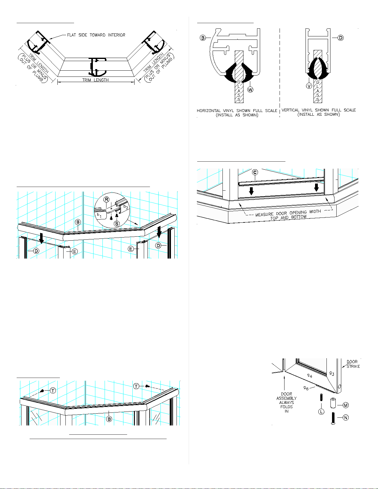
Trim Sill Pieces
Sill(A)andHeader(B)piecesareidenticalinappearanceexceptfor
the weep holes on the Sill pieces (Sill pieces have weep holes;
Header pieces do not). Trim the Sill pieces to the lengths specified
in step 1.
Assemble and Position Sill on Curb
Assemble Sill (A) by inserting Corner Brackets (R) into Sill pieces
and bringing the pieces together (see figure above and exploded
view - sheet 3).
Using the Corner Bracket holes as guides, mark and drill the Sill
pieces with a 1/8” drill bit. Secure the Corner Brackets to the Sill
pieces with eight(8) #6 x 1/4” machine screws (S). Now run a bead
of caulking on inside of crevice where Sill pieces join to insure no
leaks. PositionSillon curb. Temporarily tape Sill to curb to prevent
movement.
Position and Install Wall Jambs
PlaceWallJambs(D)intoendsofSill(A)andupagainsttheshower
wallsasshown. Plumbthe Jambs, then pencil mark the installation
hole locations on the shower walls (3 per Jamb). Remove Wall
jambs. Using a 3/16 masonry bit, drill 1-1/4” deep installation holes
in locations previously marked. Insert Plastic Screw Anchors (P)
into holes. Reposition Jambs as before and secure to wall using
six(6) 8112P Installation Screws (O)
Install 45 degree Corner Posts
GlassPanelsmusthavea1/2”insertionintotheirWallJambandthe
45 degree Corner Post in order for glazing vinyl to hold glass
properly.
Slide 45 degree Corner Posts (E) over the exposed edge of the
Glass Panels and set them into Sill cavity as shown. Double check
for 1/2” insertion before proceeding.
( 5 )5PARA_NEO_BIFOLD_12/23/99
Trim Header Pieces
Before trimming Header pieces (b2 & b3), remember to add or
subtract any out of plumb discrepancies that might exist on the
corresponding walls (as measured at top of Wall Jambs).
Trim Header (B) pieces to measurements specified in step 1 (plus
or minus any out of plumb discrepancies).
Assemble and Position Header atop Verticals
Assemble Header (B) by inserting Corner Brackets (R) into Header
pieces and bringing the pieces together (see figure above and
exploded view - sheet 3).
UsingtheCornerBracketholesasguides,markanddrilltheHeader
pieceswitha1/8”drillbit. SecuretheCornerBracketstotheHeader
pieces with eight(8) #6 x 1/4” machine screws (S). Position Header
atop verticals.
Secure Header
From interior, secure both ends of Header to Wall Jambs using one
638PHPTInstallationScrew (T)at each end.To prevent glass break-
age when drilling the Header, temporarily slide glass panel away
from Wall Jambs. When done, re-center glass panels as before.
TO PREVENT GLASS BREAKAGE
SLIDE GLASS PANELSAWAY FROM WALLJAMBS BEFORE DRILLING HEADER
Trim top & bottom Dam Strips
Measure the door opening width at Sill and Header levels. Trim top
andbottomGuideTracks(C)tomeasurementsobtained. Withhigh
lips toward exterior, position Guide Tracks on the Header and Sill
and snap them into place.
Insert Glazin Vinyls
Insert Vertical and Horizontal Glazing Vinyl (V & W) to secure the
Glass Panels (U) in place. Use a vinyl roller to speed up installation.
Install Strike Jamb
Determine which side you want your door to strike (left or right, your
choice). Once strike side has been determined, insert Strike Post
(F) into the appropriate Corner Jamb (E), magnet should be facing
toward exterior of enclosure, see exploded view - sheet 3.
Install Top and Bottom Bushings
Before proceeding with Door
Assembly installation, note
that the Door Assembly (G)
mustalwaysfoldintowardin-
terior of shower enclosure
(see exploded view - sheet
3).
Position Door Assembly on
floor the way it will be in-
stalledonenclosure(remem-
ber, unit must fold into enclosure).
InstallPivotBushings(M),PivotBushingScrews(N)andSlidePiece
Set Screws (L) onto top and bottom Slide Pieces (g6) as shown in
figure above and in exploded view - sheet 3.

( 6 )
Attach Door Handles
Attach the Door Handles (J) to the door using two(2) Door Handle
Screws (K) as shown in exploded view - sheet 3.
Install Magnet Holder
Install Magnet Holder Assembly (I) onto the bottom rail (g4) of the
“hinge side door” as shown in exploded view - sheet 3.
Note that Magnet Holder Assembly is installed as close to Center
Hinge Pull (g5) as possible. Magnet (i2) must face toward the out-
side of the shower enclosure as shown in figure.
Install Door Assembly
Pick the Door Assembly up. Now fold the Door Assembly making
sure that assembly folds in toward the shower enclosure as shown
in figure.
Insert the Door Assembly’s top and bottom Bushings (M) into cavi-
ties of the top and bottom Guide Tracks (C). Positioning the Door
Assembly diagonally to the door opening will help ease Bushing
insertion.
Once top and bottom Bushings are engaged with the top and bot-
tom Guide Tracks . . . insert the Door Assembly’s Hinge Post (g1)
into the Corner Post (E) from which it is to swing (see figure and
exploded view - sheet 3). Remember that regardless of whether the
door strikes on the left side or the on the right side . . . the Door
Assembly must always fold in toward interior of shower enclosure.
Temporarily leave as is.
Adjust Door Assembly
Step inside the shower enclosure and close the Door. Adjust Door
Assembly (G) and Strike Post (F) as needed for proper Door opera-
tion.
Note: DoorAssembly (G) bottom must always remain parallel to Sill
(A) in order for door to operate properly. Check to make sure that
bottom of DoorAssembly is parallel to the Sill. If it is not, make it so.
Whensatisfiedwithdooroperation, secureHingePost(g1)andStrike
Post(F)tothe verticalpostsusingsix(6)638PHPT Installation Screws
(T). See exploded view - sheet 3.
Install Drip Rails
Clean bottom rails of Door Assembly with alcohol to remove any oil.
Failure to clean door rails prior to installation of Drip Rails (H) may
cause tape to release.
Remove backing from tape and position Drip Rails flush with edges
of Hinge Stiles (g2) as shown in figure above and flush with bottom
of Door as shown in figure below.

( 7 )
Install Door Stop
The purpose of Door Stop (X) is to prevent the Door Panels from
hitting upon themselves.
Partiallyopenthe DoorAssembly. Measure and mark 2 inches from
hinge side as shown in figure below. Using a 1/8” drill bit, drill a pilot
hole thru center of Guide Track’s bottom (B). Using the pilot hole
you just drilled, secure Door Stop (X) to the GuideTrack with one(1)
Door Stop Screw (Y).
Install Sill Magnet
Clean the Sill face with alcohol where Magnet (Z) will make contact
with the Sill (see figure below).
Alignand bring together the magnet faces of pieces(Z&I)asshown
in figure. Remove backing from tape (z2) . . . step inside the shower
enclosure and close the DoorAssembly. Apply pressure on magnet
holdertoactivatetapeadhesiontoSill. Finishby running a 638PHPT
screw thru metals as shown in figure.
Leak Proof Your Installation
Run a bead of clear mildew resistant caulking down the full length of
each Wall Jamboutside where the Jambs meet the Walls. Now run
a bead outside where the Sill meets the curb. Follow caulking
manufacturer’sinstructionsbefore using shower (normally 24hours).
Installation is now complete. PARA_NEO_BIFOLD_12/23/99
Screws shown full scale for reference

( 8 )
Table of contents
Other Coastal Bathroom Fixture manuals


Popular Bathroom Fixture manuals by other brands


ClearGreen
ClearGreen BS1 quick start guide

Triton
Triton T60X Installation and operating instructions

Kohler
Kohler K-2440 Homeowner's guide

Sanipex
Sanipex BAGNODESIGN BDP-K9560-ESG3 Instruction guide

Homewerks Worldwide
Homewerks Worldwide H13L-421-CH quick start guide

Signature Hardware
Signature Hardware LEXIA SHWSCLE107L manual