Homewerks Worldwide H13L-421-CH User manual

Homewerks Worldwide, LLC • Lake Bluff, IL 60044 • Homewerks.com
BATHROOM FAUCET WITH
PULL-DOWN SPRAY
H13L-421-CH – Chrome nish
H13L-421-BN – Brushed nickel nish
H13L-421-ORB – Oil-rubbed bronze nish
PACKAGE AND HARDWARE CONTENTS
PART DESCRIPTION QUANTITY
A
B
C
D
E
A Faucet body 1
BPop-up drain assembly 1
CMounting nut 2
D Clip 1
EWeight 1
SAFETY INFORMATION
Please read and understand this entire manual before attempting to
assemble, operate or install the product.
WARNING
• Protect your eyes with safety glasses when cutting or soldering
water supply lines.
CAUTION
• If you solder the joints during installation, the seats, cartridges, and
washers must be removed before using a ame or the warranty will
be voided on these parts.
• Cover the sink drain to avoid losing parts.
PREPARATION
Before beginning assembly of product, make sure all parts are present.
Compare parts with package and hardware contents list. If any part is
missing or damaged, do not attempt to assemble the product. Contact
customer service for replacement parts.
Estimated Assembly Time: 30 minutes
Tools Required for Assembly (not included): Adjustable wrench, supply
lines, silicone, and screwdriver.
Installation may vary depending on how the previous faucet was installed.
Supplies necessary for the installation of the faucet are not all included;
however, they are available wherever plumbing supplies are sold.
Prior to beginning installation, turn off the hot and cold water lines, then
turn on the old faucet to release built-up pressure. When installing the
new faucet, hand tighten the connector nuts. DO NOT OVERTIGHTEN.
Connections that are too tight will reduce the integrity of the system.
Need Help? Please call our toll-free line at (877) 319-3757 (7:30 a.m. to 4:30 p.m. CST) for additional assistance or service.
10-2021
Due to constant design and quality improvements, the product may look
slightly different from the picture.

2
PRODUCT SPECIFICATIONS
Maximum Flow Rate: 1.2 GPM (4.5 LPM) at 60 PSI Ceramic cartridges
ASME A112.18.1/CSA B125 Manufactured to include no more than 0.25% weighted average lead
content on wetted surfaces
NSF/ANSI/CAN 61
Chrome, brushed nickel or oil-rubbed bronze nish
INSTALLATION INSTRUCTIONS
1. Shut off the water at the supply
valves under the sink or at the
main water supply. Disconnect
the supply lines. Remove the
existing faucet from the sink.
Clean and dry the surface area
where the new faucet will be
mounted.
15.
Attach one end of each of the water
supply lines onto the shanks (5.1)
on the faucet body (A), with hot
water on the left and cold water on
the right. Use 1/2 in. IPS faucet
connections (5.2) or supply line
coupling nuts (5.3) with 3/8 in. OD
ball-nose risers (5.4). NOTE: Do
not reuse existing supply lines.
When installing new water supply
lines, please refer to the supply line
manufacturer's installation
instructions. Tighten the supply line
connections using an adjustable or
basin wrench. Do not overtighten.
5.3
5.2
5.4
5.1
5
2.
Ensure the gasket (2.1) is in place on
the bottom of the faucet body (A).
Apply a thin bead of silicone sealant
to the underside of the gasket (2.1).
Insert the shanks (2.2) on the faucet
body (A) through the holes in the
sink (2.3). From underneath the sink,
thread the mounting nuts (C) onto
the shanks (2.2) on the faucet body
(A). Check the position of the faucet
and hand tighten until the faucet is
securely mounted. NOTE: It is helpful
to have a second person hold the
faucet in place while tightening
the mounting nuts (C).
C
A
2.1
2.2
2.3
26. To install the pop-up drain
assembly (B), remove the
bottom gasket (6.1) and
mounting nut (6.2) from the
pop-up drain assembly (B).
Push the bottom gasket (6.1)
down onto the top of the
mounting nut (6.2) and twist to
attach together.
6.2
6.1
B
6
3. Push the quick-connector (3.1)
on the end of the spray hose
(3.2) into the quick-connect
coupling (3.3) on the quick-
connect sprayer outlet (3.4).
Give the spray hose (3.2) a tug
to ensure the coupling is securely
connected. If it is necessary to
disconnect the spray hose (3.2)
from the faucet, squeeze the
tabs on the side spray quick-
connect outlet (3.4) and pull
down on the quick-connector
(3.1) on the spray hose (3.2)
to disconnect.
3.1
3.3
3.3
3.2
3.4
37. Insert the pop-up drain
assembly (B) into the drain
hole in the sink (7.1). Ensure
the top gasket (7.2) rests
securely between the top of
the sink and the top of the
drain assembly (B).
7.2
B
7.1
7
4. After connecting the spray hose
(4.1), attach the weight clip (D)
to the spray hose (4.1) at the
location indicated. To attach the
weight (E), use a screwdriver to
detach one side of the weight
(E) from the other. Then connect
the two pieces of the weight (E)
back to each other around the
spray hose (4.1).
W
e
i
g
h
t
h
e
r
e
W
e
i
g
h
t
h
e
r
e
DD
4.1
EE
4
8. From underneath the sink,
screw the bottom gasket (8.1)
and mounting nut (8.2) onto the
drain assembly (B) by twisting
until secure against the bottom
of the sink.
NOTE: Remember to reconnect
the drain body to the P-trap
drain before testing the faucet.
B
8.2
8.1
8
Homewerks.com

3
INSTALLATION INSTRUCTIONS (CONTINUED)
9. Attach each of the remaining ends
of the water supply lines (9.1) to the
hot and cold water shut-off valves
(9.2) and tighten with a wrench.
Do not overtighten.
9.1
9.2
910.
Once the installation is complete,
remove the spray head (10.1) from
the spout (10.2) on the faucet body
(A) to ush the water lines. Turn
on the water supply and allow both
hot and cold water to run for at
least one minute to ush away any
debris that could cause damage to
internal parts. While the water is
running, check for leaks. If a leak
occurs, gently tighten the nut on
the connection that is leaking. Fill
the sink with water to check the
drain for leaks. If water is leaking
from the drain, tighten the nut on
the drain assembly and empty
the sink. Turn off the water and
screw the spray head (10.1) back
onto the spout (10.2) of the faucet
body (A).
10.1
A
10.2
10
Homewerks.com
CARE AND CLEANING
Clean periodically with a soft cloth. Avoid abrasive cleaners, steel wool, and harsh chemicals as these will dull the nish and void your
warranty.
TROUBLESHOOTING
If a faucet installation doesn't deliver water properly or leaks, nding the cause and xing it can be easy.
PROBLEM POSSIBLE CAUSE SOLUTION
Faucet leaks
underneath handle. Bonnet has come loose or the
ceramic cartridge seal is dirty or
out of place.
1. Move the handle to the OFF position. Unscrew the handle screw and remove the
handle.
2. Tighten the bonnet by turning it clockwise. Move the cartridge stem to the ON position.
The leak should stop draining out from around the cartridge stem.
3. If the leak does not stop, shut off the water supply. Remove the bonnet by turning it
counterclockwise. Lift out the ceramic cartridge. Inspect the seal on the bottom of the
ceramic cartridge. Remove any debris from the seal. If the ceramic cartridge seal is
twisted or out of place, re-seat it. If the ceramic cartridge seal is worn or damaged,
replace the cartridge by calling customer service.
4. Position the cartridge back into the faucet body. Make sure the ridges on the two sides
of the cartridge bonnet t into the grooves on the two sides of the faucet body. Tightly
screw the bonnet onto the faucet body.
5. Reinstall the handle.
Water does not
completely shut off. Ceramic cartridge discs are
worn or have debris trapped
inside.
1. Shut off the water supply.
2. Move the handle to the OFF position. Unscrew the handle screw and remove the
handle.
3. Remove the bonnet. Lift out the ceramic cartridge.
4. Position the new ceramic cartridge into the faucet body.
5. Tightly screw the bonnet into the faucet body.
6. Reinstall the handle.
Faucet leaks around
aerator. The aerator is incorrectly tted,
dirty, or small parts inside the
aerator are improperly installed.
1. Remove the aerator from the spout on the faucet body. Inspect the black rubber gasket
inside the aerator. The rubber gasket should be at.
2. Reinstall the aerator on the spout.
Faucet has an improper
water pattern. The aerator is dirty or small parts
inside the aerator are improperly
installed.
1. Remove the aerator from the spout on the faucet body.
2. Gently ush the small parts inside the aerator to clear away any debris.
3. Reinstall the aerator on the spout.
No water pressure or
low water pressure after
a longer period of use.
The connector is blocked. 1. Remove the spray head by unscrewing it from the hose assembly.
2. Hold the end of the hose assembly down into the sink and turn the faucet on to the
warm position where it mixes the hot and cold water. If the water ow is still slow or
completely blocked, please call customer service.
OPERATING INSTRUCTIONS
The lever handles control the ow of hot and cold water to the faucet. Moving the handle forward opens the cartridge and causes water
to ow from the spout. Rotate the handle on the right side of the faucet forward for cold water. Rotate the handle on the left side of the
faucet forward for hot water. The degree of handle opening determines the volume of water ow. Returning the handle to the original
position away from the spout on the faucet body stops the ow of water.

4Homewerks.com
ROUGH-IN
4"
8 1/2"
9"
1/2"-14NPSM-2A
1 1/4"
5 3/8"
7"
4 3/4"
2 1/8"
REPLACEMENT PARTS
For replacement parts, call our customer service department at (877) 319-3757, 7:30 a.m. - 4:30 p.m., CST, Monday - Friday.
PART DESCRIPTION PART # PART # PART #
H13L-421-CH H13L-421-BN H13L-421-ORB
1Handle RP 13617CH RP 13617BN RP 13617ORB
2Set screw RP 50002 RP 50002 RP 50002
3Index button - hot RP 10004 RP 10004 RP 10004
4Index button - cold RP 10005 RP 10005 RP 10005
5Bonnet RP 70678 RP 70678 RP 70678
6Cartridge - hot RP 20067 RP 20067 RP 20067
7Cartridge - cold RP 20068 RP 20068 RP 20068
8Mounting nut RP 56131 RP 56131 RP 56131
9Connector clip RP 70421 RP 70421 RP 70421
10 O-ring RP 60002 RP 60002 RP 60002
11 Spray head RP 38434CH RP 38434BN RP 38434ORB
12 Weight clip RP 70590 RP 70590 RP 70590
13 Weight RP 70685 RP 70685 RP 70685
14 Pop-up drain assembly RP 40269CH RP 40269BN RP 40269ORB
LIMITED LIFETIME WARRANTY
The distributor warrants to the original consumer purchaser this product to be free from
defects in material and workmanship under normal use in residential applications. At its
option, the Company will provide repair parts or replace defective product when the product
is used in accordance with the manufacturer’s specications.
The distributor provides a limited 5-year warranty on the nish of this product to the original
purchaser. At its option, the distributor will provide repair parts or replace defective product
when the product is used in accordance with the manufacturer’s specications. Use of mild
abrasive, abrasive or chemical cleaners may damage the nish of the faucet. We recommend
cleaning your faucet with a soft cloth, moistened with water. Damage resulting from the use
of abrasive or chemical cleaners SHALL VOID THIS WARRANTY.
This warranty is not applicable to any products or parts of products where damage is caused
by use of non-genuine parts; is due to installation error, product misuse, negligence or faulty
maintenance; or where the product is not installed according to local building codes.
This warranty excludes labor charges or damage incurred during installation,
repair or replacement, and any indirect, incidental or consequential damages,
losses, injury or costs of any nature. This warranty is in lieu of and excludes
all other warranties, conditions and guarantees, whether expressed or
implied, including without restriction those of merchantability or tness of use.
Liability under this warranty will not exceed the purchase price for the product
claimed to be defective by the original consumer purchaser. Some states or
provinces do not allow the exclusion or limitation of consequential damages
so the above limitations or exclusions may not apply. This warranty gives you
specic legal rights and you may also have other rights which vary from state
to state, or province to province.
Inquiries regarding warranty claims can be directed to (877) 319-3757, 7:30
a.m. - 4:30 p.m., CST, Monday - Friday.
11
01
02
06
07
03
04
05
8
9
10
12
13
14

GRIFO DE BAÑO CON ROCIADOR EXTRAÍBLE
H13L-421-CH – Acabado de cromo
H13L-421-BN– Acabado en níquel cepillado
H13L-421-ORB – Acabado en bronce aceitado
CONTENIDO DEL PAQUETE Y HARDWARE
PARTE DESCRIPCIÓN CANTIDAD
A
B
C
D
E
ACuerpo del grifo 1
BConjunto de drenaje emergente 1
CTuerca de montaje 2
DPinza 1
E Peso 1
INFORMACIÓN SOBRE LA SEGURIDAD
Lea y comprenda completamente este manual antes de intentar ensamblar,
usar o instalar el producto.
ADVERTENCIA
• Proteja los ojos con gafas de seguridad al cortar o soldar las tuberías
de suministro de agua.
PRECAUCIÓN
• Si suelda las juntas durante la instalación del grifo, se deben retirar los
asientos, los cartuchos y las arandelas antes de usar la llama. De lo
contrario, se anulará la garantía de dichas piezas.
• Cubra el desagüe del lavamanos para evitar perder partes.
PREPARACIÓN
Antes de comenzar a ensamblar el producto, asegúrese de tener todas
las piezas. Compare las piezas con la lista del contenido del paquete y
hardware. No intente ensamblar el producto si falta alguna pieza o si
estas están dañadas. Póngase en contacto con el servicio al cliente para
obtener piezas de repuesto.
Tiempo estimado de ensamblaje: 30 minutos
Herramientas necesarias para el ensamblaje (no se incluyen): Llave
ajustable, las tuberías de suministro, silicona, y destornillador.
La instalación puede variar según cómo se instaló el grifo anterior. No se
incluyen todos los materiales necesarios para la instalación del grifo; no
obstante, estos están disponibles en cualquier lugar donde se vendan
artículos de plomería.
Antes de comenzar la instalación, cierre las líneas de entrada de agua
fría y caliente, y luego abra el grifo viejo para liberar la presión
acumulada. Al instalar el nuevo grifo, primero apriete a mano las tuercas
del conector. NO APRIETE DEMASIADO. Las conexiones que estén muy
apretadas reducirán la integridad del sistema.
¿Necesitas Ayuda? Llame a nuestra línea gratuita al (877) 319-3757 (7:30 a.m. to 4:30 p.m. CST) para obtener asistencia o servicio adicional.
SIN
PLOMO
CUMPLE
CON ADA
Homewerks Worldwide, LLC • Lake Bluff, IL 60044 • Homewerks.com
Debido a las constantes mejoras de diseño y calidad, es posible que el
producto se vea ligeramente diferente de la imagen.

6Homewerks.com
ESPECIFICACIONES DEL PRODUCTO
Caudal de ujo máximo: 4,5 LPM (1,2 GPM) a 60 PSI Cartuchos de cerámica
ASME A112.18.1/CSA B125 Fabricado para incluir un contenido medio ponderado de plomo de no
más del 0,25 % en supercies mojadas
NSF/ANSI/CAN 61
Acabados en cromo pulido, níquel cepillado o bronce aceitado
INSTRUCCIONES DE INSTALACIÓN
1. Cierre las válvulas de suministro
de agua debajo del lavamanos o
el suministro de agua principal.
Desconecte las tuberías de
suministro. Retire el grifo
existente del lavamanos.
Limpie y seque el área supercial
donde se colocará el nuevo grifo.
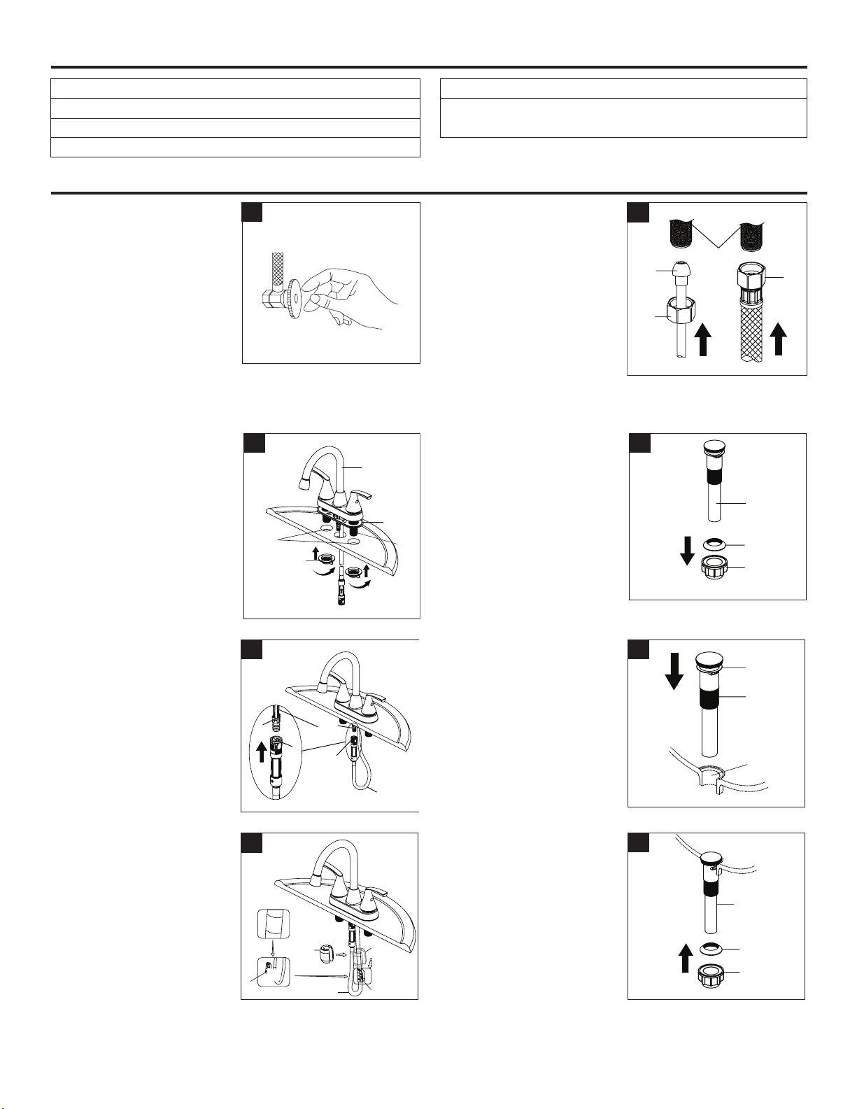
15.
Conecte un extremo de cada una de
las tuberías de suministro de agua en
los vástagos (5.1) del cuerpo del grifo
(A), con el agua caliente a la izquierda
y el agua fría a la derecha. Use
conexiones de grifo IPS de 1/2 pulg.
(5.2) o tuercas de acoplamiento para la
tubería de suministro (5.3) con
elevadores de punta esférica de 3/8
pulg. de diámetro externo (5.4). NOTA:
no reutilice las tuberías de suministro
existentes. Al instalar nuevas tuberías
de suministro de agua, consulte las
instrucciones de instalación del
fabricante de la tubería de suministro.
Apriete las conexiones de la tubería de
suministro con una llave ajustable o
llave para lavamanos. No apriete
demasiado.
5.3
5.2
5.4
5.1
5
2.
Asegúrese de que el empaque (2.1)
esté en su lugar en la parte inferior del
cuerpo del grifo (A). Aplique un cordón
delgado de sellador de silicona en la
parte inferior del empaque (2.1).
Inserte los vástagos (2.2) del cuerpo del
grifo (A) en los oricios del lavamanos
(2.3). Desde debajo del lavamanos,
enrosque las tuercas de montaje (C) en
los vástagos (2.2) del cuerpo del grifo
(A). Verique la posición del grifo y
apriete a mano hasta que el grifo esté
instalado de forma segura. NOTA: es
útil que una segunda persona sostenga
el grifo en su lugar mientras apreita las
tuercas de montaje (C).
C
A
2.1
2.2
2.3
26. Para instalar el conjunto de
drenaje emergente (B), retire la
junta inferior (6.1) y la tuerca de
montaje (6.2) del cuerpo del
conjunto de drenaje (B). Empuje
la junta inferior (6.1) hacia abajo
en la parte superior de la tuerca
de montaje (6.2) y gírela para
unirla.
6.2
6.1
B
6
3.
Empuje el conector rápido (3.1) en el
extremo de la manguera del rociador
(3.2) dentro del acoplamiento de
conexión rápida (3.3) en la salida de
conexión rápida (3.4) del rociador.
Apriete la manguera del rociador (3.2)
para asegurarse de que el
acoplamiento esté conectado. Si es
necesario desconectar la manguera
del rociador (3.2) del grifo, presione
las lengüetas en la salida de conexión
rápida del rociador (3.4) y jale hacia
abajo el conector rápido (3.1) en la
manguera del rociador (3.2) para
desconectar.
3.1
3.3
3.3
3.2
3.4
37. Inserte el conjunto de drenaje
emergente (B) en el oricio de
drenaje en el lavamanos (7.1).
Asegúrese de que la junta
superior (7.2) descanse
rmemente entre la parte
superior del lavamanos y la parte
superior del conjunto de drenaje
emergente (B).
7.2
B
7.1
7
4. Después de conectar la
manguera del rociador (4.1),
je la pinza de pesa (D) a la
manguera del rociador (4.1) en
la ubicación indicada. Para jar
la pesa (E), use un destornillador
para separar un lado de la pesa
(E) del otro. Luego, vuelva a
conectar las dos piezas de la
pesa (E) entre sí alrededor de la
manguera del rociador (4.1).
W
e
i
g
h
t
h
e
r
e
W
e
i
g
h
t
h
e
r
e
DD
4.1
EE
4
8. Desde debajo del lavamanos,
atornille el conjunto de la junta
inferior (8.1) y la tuerca de
montaje (8.2) en el conjunto de
drenaje emergente (B) girándolo
en el sentido horario hasta que
quede jo contra el fondo del
lavabo.
NOTA: recuerde conectar el
cuerpo del desagüe a la trampa
en P antes de probar el grifo.
B
8.2
8.1
8
peso
aquí

7
Homewerks.com
INSTRUCCIONES DE INSTALACIÓN (CONTINUACIÓN)
9. Conecte cada uno de los
extremos restantes de las
tuberías de entrada de agua (9.1)
a las válvulas de cierre de agua
fría y caliente (9.2), y apriete
con una llave inglesa. No apriete
demasiado.
9.1
9.2
9
10.
Una vez completada la instalación,
retire el cabezal rociador (10.1) del
caño (10.2) en el cuerpo del grifo
(A) para descargar las tuberías de
agua. Abra el suministro de agua y
deje correr el agua fría y caliente
durante al menos un minuto para
eliminar cualquier residuo que
pueda dañar las piezas internas.
Mientras el agua está corriendo,
verique que no haya fugas. Si se
produce una fuga, apriete
suavemente la tuerca de la
conexión que tiene la fuga. Llena
el lavamanos con agua para
comprobar que no haya fugas en
el desagüe. Si sale agua por el
desagüe, apriete la tuerca del
conjunto de desagüe y vacíe el
lavamanos. Cierre el agua y
vuelva a enroscar el cabezal
rociador (10.1) en el caño (10.2)
del cuerpo del grifo (A).
10.1
A
10.2
10
CUIDADO Y LIMPIEZA
Limpie periódicamente con un paño suave. Evite utilizar limpiadores abrasivos, estropajo de acero y químicos cáusticos porque podrían arruidar el acabado y
anular la garantía.
SOLUCIÓN DE PROBLEMAS
Si la instalación de un grifo no suministra agua correctamente o tiene fugas, puede ser fácil encontrar la causa y solucionarlo.
PROBLEMA CAUSA POSIBLE SOLUCIÓN
El grifo tiene una
fuga debajo de la
manija.
El casquete se ha aojado o el
sello del cartucho de cerámica
está sucio o fuera de lugar.
1. Mueva la manija a la posición APAGADO. Desatornille el tornillo de la manija y retire la manija.
2. Apriete el casquete girándolo en sentido horario. Mueva el vástago del cartucho a la posición
ABIERTA. La fuga debe dejar de salir alrededor del vástago del cartucho.
3. Si la fuga no se detiene, cierre el suministro de agua. Retire el casquete girándolo en sentido
antihorario. Saque el cartucho de cerámica. Inspeccione el sello en la parte inferior del cartucho
de cerámica. Retire cualquier residuo del sello. Si el sello del cartucho de cerámica está torcido
o fuera de lugar, vuelva a asentarlo. Si el sello del cartucho de cerámica está desgastado o
dañado, reemplace el cartucho llamando al servicio de atención al cliente.
4. Vuelva a colocar el cartucho en el cuerpo del grifo. Asegúrese de que las crestas de los dos
lados del casquete del cartucho encajen en las ranuras de los dos lados del cuerpo del grifo.
Atornille rmemente el casquete en el cuerpo del grifo.
5. Vuelva a instalar la manija.
El paso de agua
no se cierra
completamente.
Los discos de cartucho de
cerámica están desgastados o
tienen residuos atrapados en
su interior.
1. Cierre el suministro de agua.
2. Mueva la manija a la posición APAGADO. Desatornille el tornillo de la manija y retire la manija.
3. Quite el casquete. Saque el cartucho de cerámica.
4. Coloque el nuevo cartucho de cerámica en el cuerpo del grifo.
5. Enrosque rmemente el casquete en el cuerpo del grifo.
6. Vuelva a instalar la manija.
El grifo tiene fugas
alrededor del
aireador.
El aireador está mal instalado,
sucio o las piezas pequeñas
dentro del aireador están
instaladas incorrectamente.
1. Retire el aireador de la boquilla en el cuerpo del grifo utilizando la tecla de aireador o una
moneda. Inspeccione el empaque de goma negro en el interior del aireador. El empaque de
goma debe ser plano.
2. Vuelva a instalar el aireador en la boquilla.
El grifo tiene un
patrón de agua
incorrecto.
El aireador está sucio o se
instalaron piezas pequeñas de
manera incorrecta dentro del
aireador.
1. Retire el aireador de la boquilla en el cuerpo del grifo.
2. Limpie cuidadosamente las piezas pequeñas dentro del aireador para retirar cualquier
desecho.
3. Vuelva a instalar el aireador en la boquilla.
INSTRUCCIONES DE FUNCIONAMIENTO
Las manijas de palanca controlan el ujo de agua caliente y fría del grifo. Mover la manija hacia delante abre el cartucho y hace que el agua uya desde el caño.
Gire la manija en el lado izquierdo del grifo hacia delante para obtener agua caliente. Gire la manija en el lado derecho del grifo hacia delante para obtener agua
fría. El grado en que abra la manija determina el volumen del ujo de agua. Al volver la manija a la posición original, lejos de el caño, se detiene el ujo de agua.

8Homewerks.com
DIBUJO DE INSTALACIÓN
4"
8 1/2"
9"
1/2"-14NPSM-2A
1 1/4"
5 3/8"
7"
4 3/4"
2 1/8"
PIEZAS DE REPUESTO
Para piezas de repuesto, llame a nuestro servicio al cliente al (877) 319-3757, 7:30 a.m. - 4:30 p.m., CST, de lunes a viernes.
PARTE DESCRIPCIÓN PARTE # PARTE # PARTE #
H13L-421-CH H13L-421-BN H13L-421-ORB
1Manija RP 13617CH RP 13617BN RP 13617ORB
2Tornillo RP 50002 RP 50002 RP 50002
3Botón de índice - caliente RP 10004 RP 10004 RP 10004
4Botón de índice - frío RP 10005 RP 10005 RP 10005
5Capó RP 70678 RP 70678 RP 70678
6Cartucho de cerámica:
agua caliente RP 20067 RP 20067 RP 20067
7Cartucho de cerámica:
agua fría RP 20068 RP 20068 RP 20068
8Tuerca de montaje RP 56131 RP 56131 RP 56131
9Sujetador del conector RP 70421 RP 70421 RP 70421
10 Junta tórica RP 60002 RP 60002 RP 60002
11 Cabezal rociador RP 38434CH RP 38434BN RP 38434ORB
12 Sujetador de peso RP 70590 RP 70590 RP 70590
13 Peso RP 70685 RP 70685 RP 70685
14 Conjunto de drenaje emergente RP 40269CH RP 40269BN RP 40269ORB
GARANTÍA LIMITADA DE POR VIDA
El distribuidor garantiza al comprador original que este producto está libre de defectos en
cuanto a los materiales y la mano de obra en condiciones de uso normal en aplicaciones
residenciales. A su elección, la Compañía proporcionará piezas de repuesto o
reemplazará un producto defectuoso si el producto se utilizó de acuerdo con las
especicaciones del fabricante.
El distribuidor le brinda al comprador original una garantía limitada de 5 años para el
acabado de este producto. A su elección, el distribuidor proporcionará piezas de repuesto
o reemplazará un producto defectuoso si el producto se utilizó de acuerdo con las
especicaciones del fabricante. El uso de limpiadores abrasivos suaves, abrasivos o
químicos puede dañar el acabado del producto. Le recomendamos que limpie el grifo con
un paño suave y humedecido con agua. El daño ocasionado por el uso de limpiadores
abrasivos o químicos ANULARÁ ESTA GARANTÍA.
Esta garantía no se aplica a productos o piezas de productos si el daño fue ocasionado
por el uso de piezas no originales; o se deba a un error de instalación, al mal uso del
producto, a negligencia o al mantenimiento inadecuado; o en caso de que el producto no
se haya instalado de acuerdo con los códigos de construcción locales.
Esta garantía no incluye los cargos por mano de obra o los daños
ocasionados durante la instalación, la reparación o el reemplazo, ni las
lesiones, las pérdidas o los daños indirectos, accidentales o resultantes,
ni los costos de ninguna naturaleza. Esta garantía reemplaza y excluye
todas las demás garantías y condiciones, expresas o implícitas, incluidas
sin restricción aquellas de comerciabilidad o uso adecuado.
La responsabilidad bajo esta garantía no superará el precio de compra del
producto que se reclama como defectuoso pagado por el cliente o
comprador original. Algunos estados o provincias no permiten la exclusión
o limitación de los daños accidentales o resultantes, de modo que es
posible que no se apliquen las exclusiones o limitaciones mencionadas
anteriormente. Esta garantía le otorga derechos legales especícos y
también puede tener otros derechos que varían de estado a estado, o de
provincia a provincia.
Las consultas sobre reclamos de garantía pueden dirigirse a 1-877-319-
3757, de 7:30 a.m. a 4:30 p.m., CST, de lunes a viernes.
11
01
02
06
07
03
04
05
8
9
10
12
13
14
This manual suits for next models
2
Table of contents
Languages:
Other Homewerks Worldwide Bathroom Fixture manuals
Popular Bathroom Fixture manuals by other brands

Kohler
Kohler Mira Sport Max J03G Installation and user guide

Moen
Moen 186117 Series installation guide

Hans Grohe
Hans Grohe Raindance Showerpipe 27235000 Instructions for use/assembly instructions

Signature Hardware
Signature Hardware ROUND SWIVEL BODY SPRAY 948942 Install

fine fixtures
fine fixtures AC3TH installation manual

LIXIL
LIXIL HP50 Series quick start guide