EQUIPMENT MANUAL 250-16-1 REV -
250/250-16-1 Amendment #3 Aug 9, 2011 Page c
PROPRIETARY AND CONFIDENTIAL TO COBHAM
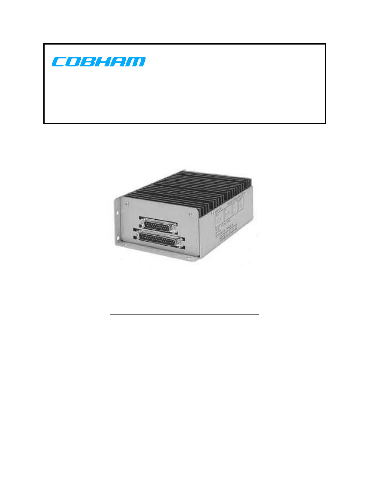
MODEL 250 DETAIL PART NUMBER DESCRIPTIONS
The detail part numbers associated with the Model 250 Passenger Speaker Amplifier may
define different level adjustments and/or test procedures than those outlined in the
calibration and test table of document No. 250-4, Acceptance Test Procedure. Table A
describes those differences.
NOTE: A Model 250 with an associated detail part number is designated as a Model 250-XXX,
where XXX is the applicable detail part number.
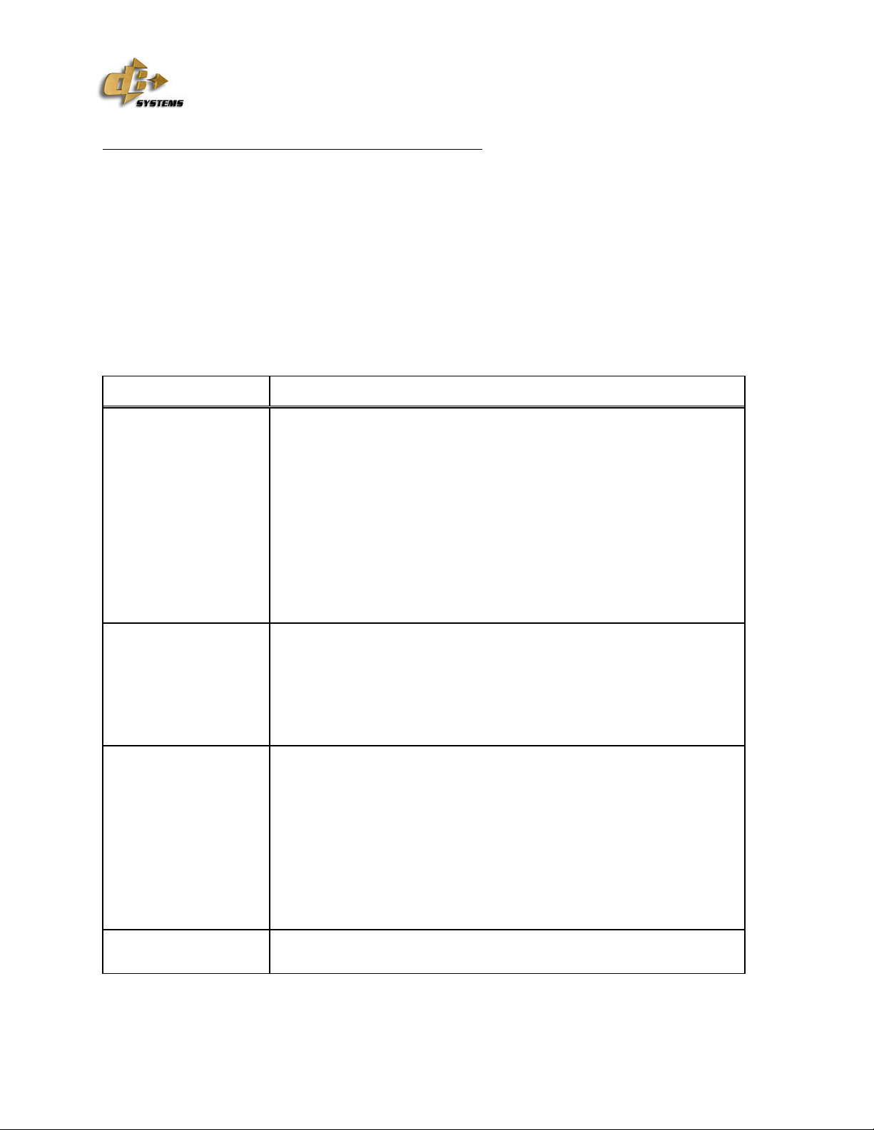
Table A. Detail Part Number Description
Detail Part Number Description of Difference
001 Low Pass Filters adjusted for –3 dB attenuation at 70 Hz on Left
and Right Speaker Outputs. High Pass Filters adjusted for –3 dB
attenuation at 20 Khz on Left and Right Speaker Outputs.
-001 calibration is designed for use with
dB Systems 250-61, 4-inch speakers.
MOD A units use PCB 250-81 to prevent speaker popping on
power up. MOD B units include PCB 250-91 in place of PCB 250-
81. MOD C units include modifying component value of C1 and
C27 to fix high frequency oscillation problem. PCB 250-52
includes the increased stereo gain.
002 The Model 250-002 has no differences from the Base Model.
MOD A units use PCB 250-81 to prevent speaker popping on
power up. MOD B units include PCB 250-91 in place of PCB 250-
81. MOD C units include modifying component value of C1 and
C27 to fix high frequency oscillation problem. PCB 250-52
includes the increased stereo gain.
003 Identical to Base Model with the following changes:
- Stereo Left and Stereo Right inputs are reduced to 0.45 Vrms.
- Stereo Left and Stereo Right input gain is increased so that the
outputs are the same as the Base Model.
MOD A units use PCB 250-81 to prevent speaker popping on
power up. MOD B units include PCB 250-91 in place of PCB 250-
81. MOD C units include modifying component value of C1 and
C27 to fix high frequency oscillation problem. PCB 250-52
includes the increased stereo gain.