COBIA 301CC User manual

Model Year 2019 page 1
Maverick Boat group, Inc. • 3207 Industrial 29th St. • Fort Pierce, Florida 34946 • (772)-465-0631 or (888)-shallow • Fax: (772) 489-2168
` COBIA 301CC
WELCOME
Dear New Cobia Owner,
On behalf of Cobia Boats, I would like to congratulate
you on your purchase. We at Cobia strive to build the
best products possible and wish you years of trouble
free enjoyment. There are many things to know about
the operation, care and maintenance of our products
and the systems we install in them. Please review all
the applicable information for your new boat. The
more you know, the more you will enjoy your new
Cobia.
Again, a heartfelt Thank You from myself and the
whole Cobia Family.
Scott Deal, President and CEO
OWNER’S MANUAL

Model Year 2019 page 2
Maverick Boat group, Inc. • 3207 Industrial 29th St. • Fort Pierce, Florida 34946 • (772)-465-0631 or (888)-shallow • Fax: (772) 489-2168
TABLE OF CONTENTS
Specifications……………………………………..………………….2
Pre-Operation Checklist…………………………………………….3
Yamaha Engine Break-In Periods................................................4
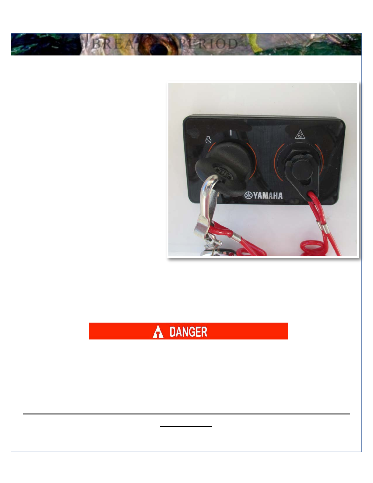
Engine Stop Switch......................................................................4
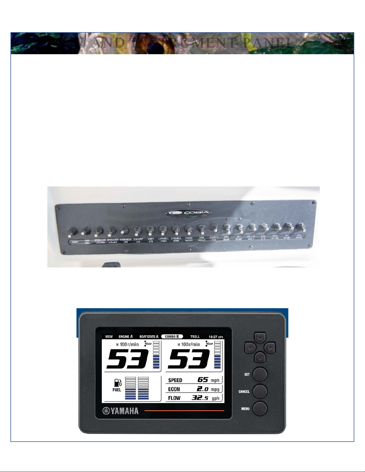
Switch Panels...............................................................................5
Instrument Panel with Yamaha Multi-Function Gauges…….……5
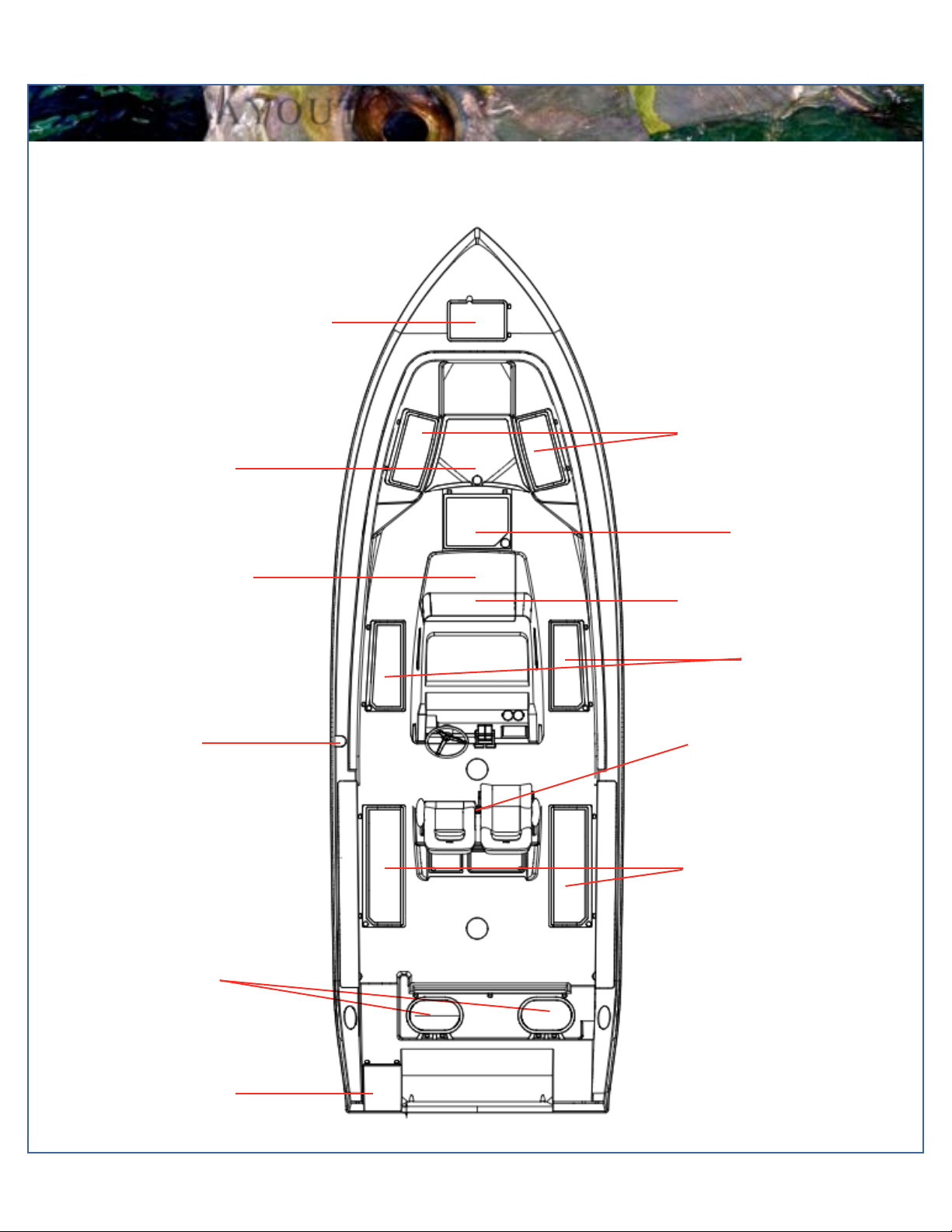
301 Boat Layout………………………………………………….…..6
Cobia Duffel Bag..........................................................................7
Fuel/Water Separators.................................................................8
Garboard Drain Plug....................................................................8
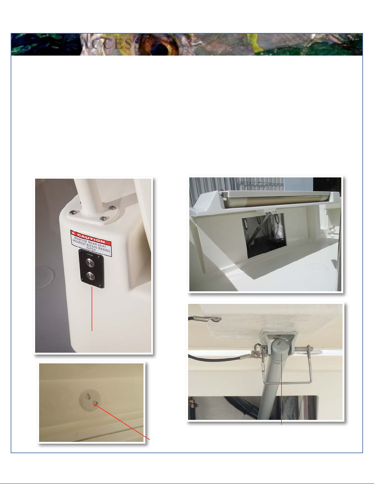
Bilge Access.................................................................................9
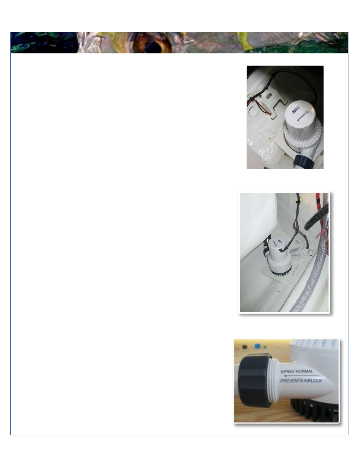
Bilge System…………………………………………………..….…10
Ball Valves, Thru Hull Fittings & Scuppers………….……………11
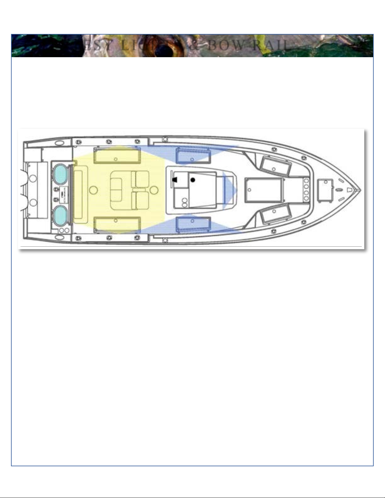
Cockpit Courtesy Lights & Bow Rail……..……………………….12
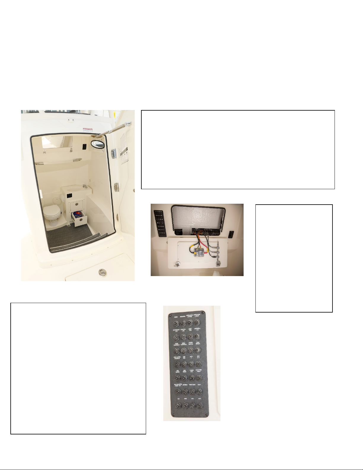
Head Systems…………………………………………………..13-15
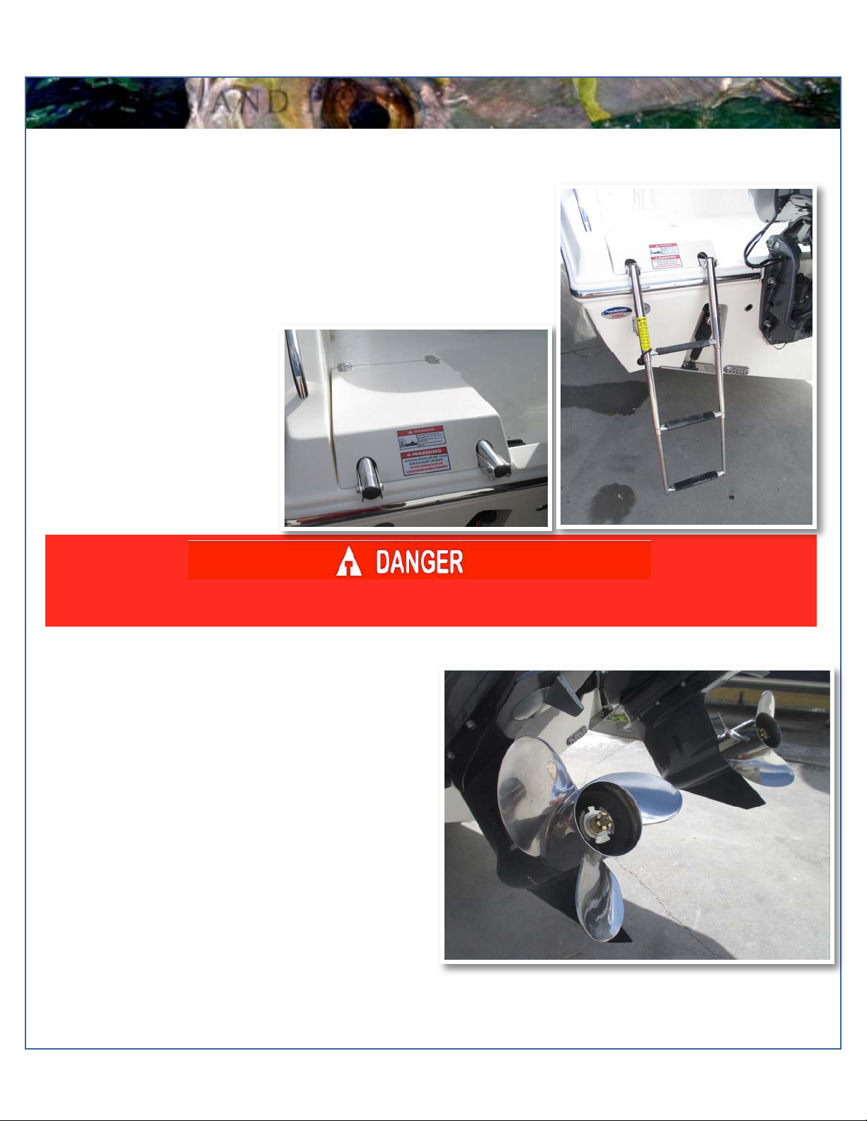
Stainless Boarding Ladder.........................................................16
Props..........................................................................................16
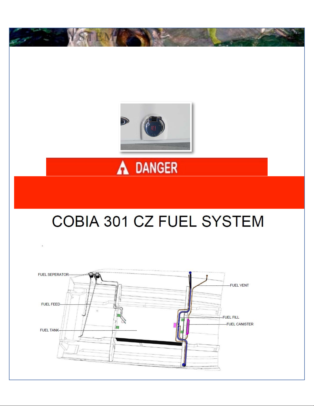
Fuel System...............................................................................17
Steering......................................................................................18
Self Bailing Cockpit....................................................................19
Livewell System.........................................................................20
Fish Lockers...............................................................................20
Anchor Locker / Rode Storage…………………………………….21
Table Lift…….……………………………………………………….21
Trim Tabs………………….……………………………………..….22
Macerators………………………………………………………..…23
Console Access & Saltwater Washdown…………………….…..24
Freshwater System................................................................25
Battery Switch & Distribution Panel.……………………….26-27
Battery Charger………………………………………………….28
12 Volt Accessory Plug…………………………………………28
Leaning Post & Battery Access..………………………………29
Aft Seating……………………………………………………..…30
Optional Bow Cushion Set.....................................................30
Cockpit Bolsters.....................................................................31
Pop-up Bow Light & Cleats……………………………………..31
T-Top Options........................................................................32
Kite/Rod Holders....................................................................33
Optional Stereo System.........................................................34
Optional Windlass System………………………………….34-35
Wiring System Diagrams……………………………………36-38
Warranty………………………………………………………… 39
301 SPECIFICATIONS
L.O.A............................................................29’ 07”
BEAM...........................................................10’ 00”
DRAFT...............................................................21”
WEIGHT W/O ENGINE..........................5915 LBS.
FUEL CAPACITY.....................................230 GAL.
DEADRISE @ TRANSOM......................21.5 DEG
MAXIMUM H.P............................................600 HP
TRANSOM HEIGHT…….......................25”TWINS

Model Year 2019 page 3
Maverick Boat group, Inc. • 3207 Industrial 29th St. • Fort Pierce, Florida 34946 • (772)-465-0631 or (888)-shallow • Fax: (772) 489-2168
PRE-OPERATION CHECKLIST
*******PRE OPERATION CHECK LIST*******
(we recommend that you remove the checklist and store at the helm station)

Model Year 2019 page 4
Maverick Boat group, Inc. • 3207 Industrial 29th St. • Fort Pierce, Florida 34946 • (772)-465-0631 or (888)-shallow • Fax: (772) 489-2168
ENGINE BREAK-IN PERIOD
Engine stop switch (above)
Engine Break-In Period
New engines require a period of break-in to allow
the surfaces of the moving parts to mate evenly.
Different engines require different break-in periods
and methods. For instructions on break in
methods, refer to your Yamaha Engine Owner’s
Manual for the correct break-in procedures and
times for your model engines
Engine Stop Switch
If activated, the spring loaded engine stop switch
will automatically shut down the engine during
emergency situations to prevent uncontrolled or
unattended operation. Certain emergency
conditions (e.g., turbulent water, wakes,
unanticipated movement) may impair a person’s
ability to operate the craft safely. The switch,
located on the helm, must have the safety lanyard
attached at its base. This activates the protective
shutdown circuitry.
Securely attach the other end of the lanyard to the
operator of the boat. If the operator moves, falls or
is at an unsafe distance from the steering wheel,
tension on the lanyard will pull it from the switch.
When the lanyard is removed, the engine stop
switch is released and automatic engine shutdown
occurs.
Engine Stop Switch
An engine stop switch system that is not used or does not function properly can cause death or serious injury.
DO NOT operate the boat if the engine stop switch system does not function properly. Go to a Cobia Dealer to
have this resolved immediately.
The lanyard should be securely attached to the boat operator at all times that the
engine is on.

Model Year 2019 page 5
Maverick Boat group, Inc. • 3207 Industrial 29th St. • Fort Pierce, Florida 34946 • (772)-465-0631 or (888)-shallow • Fax: (772) 489-2168
Switch Panel & Helm
At the helm of your Cobia, you have a main switch panel, which is located above the steering wheel. This panel controls your
lights, horn, accessories, livewell, and your bilge. While most of the switches are simple “on/off” switches, some of the
switches are “on/off/on” and control two accessories as denoted by the labels. For the”on/off” switches simply push the switch
up to activate that accessory. For the “on/off/on” switches push the switch in the direction of the accessory labeled by its
order on the label below the switch. To the right of the steering wheel you have your two trim tab switches, (Refer to page 22
for trim tab operation.) The boat also comes standard with a compass mounted on top of the console.
When the indicators above the bilge switches are illuminated in red that means the bilge pump is running from its float switch
being activated. It is not uncommon for the float switches to be activated for a few seconds for a couple periods over the
course of a full day on the water. However, if the bilge indicators stay on for a prolonged period or come on numerous times,
this is likely evidence of a leak and the bilge should be checked immediately for water intrusion. Any leaking should be
addressed right away. For more information on the bilges, bilge pumps and bilge switches, refer to page 10.
Command Link Gauges
Yamaha’s new 6YC Command Link gauge comes standard on your new Cobia. This gauge allows access to more
information and is user-selectable so you can choose the functions displayed. To learn the gauge’s full functionality refer to
your Yamaha engine owner’s manual located in the Cobia duffel bag.
SWITCH AND INSTRUMENT PANEL

Model Year 2019 page 6
Maverick Boat group, Inc. • 3207 Industrial 29th St. • Fort Pierce, Florida 34946 • (772)-465-0631 or (888)-shallow • Fax: (772) 489-2168
BOAT LAYOUT
301 Deck Layout
Storage Hatches
Anchor Locker/Raw Water Washdown
Table Lift
Cooler Box
Forward Console/Head Entry
Fuel Fill
Fwd. Dry
80 Gal. Fish Lockers
Leaning Post/Tackle Station
Boarding Ladder
28 Gal. Livewells
Mid Dry Storage

Model Year 2019 page 7
Maverick Boat group, Inc. • 3207 Industrial 29th St. • Fort Pierce, Florida 34946 • (772)-465-0631 or (888)-shallow • Fax: (772) 489-2168
COBIA DUFFEL BAG
Cobia Duffel Bag
Along with your boat, you received a Duffel Bag with your new Cobia. Inside the
Duffel Bag are the following items:
Large Livewell Standpipe
1.5” Livewell Pacifier Plug
2 ignition Keys and Emergency Kill Cord /Engine Stop Lanyard
Yamaha Engine Owner’s Manuals
Engine Start Cord
Various Accessories Manuals

Model Year 2019 page 8
Maverick Boat group, Inc. • 3207 Industrial 29th St. • Fort Pierce, Florida 34946 • (772)-465-0631 or (888)-shallow • Fax: (772) 489-2168
Fuel-water Separators
Fuel-Water Separator
A Yamaha Fuel - Water Separator is installed
starboard side of the bilge area on the 301. The
new, improved 10-micron filter provides superior
filtration ahead of the engine's onboard filters and
injectors. Large filtering and water capture areas
maximize filtration while maintaining adequate flow
rate for larger engines.
The fuel separator can be checked by removing it
from the mounting bracket and dumping it into
an approved waste collection device. If there
appears to be an excessive amount of water, the
filter component should be replaced. See your
authorized Cobia Dealer for replacement parts.
The micron filter and head are pictured to the right.
It is mounted inside an access panel located aft of
the port transom gate. The fuel system primer bulb
is located next to the filter.
Maintenance Note
Yamaha recommends replacing the 10- micron fuel filter on new boats after the first 10 hours or 1 month of
operation and every 50 hours or every 6 months thereafter. In areas of high humidity where water in fuel supplies is a
problem or extensive engine operation occurs, more frequent replacement may be necessary.
Garboard Drain Plug
The garboard drain plug is the small metal plug located at
the lowest point on the hull, at the bottom of the transom
right above the keel. The drain has been designed to so
that it can be loosened by hand while the hull is out of the
water for draining. This allows the plug to stay in contact
with the surrounding frame so you’ll never misplace or
lose it. You can completely remove the insert by pulling
back and continue turning in a counter clockwise motion.
It is manufactured with a rubber seal in place to ensure
your bilge is watertight. Always make sure before putting
the boat in the water that this plug is hand tightened
firmly. Excess water in the bilge may be an indication of a
problem with this plug or the automatic bilge pump. Refer
to page 10 of this Owner’s Manual for information on your
boats bilge system.
FUEL-WATER SEPARATOR & DRAIN
PLUG

Model Year 2018 page 9
Maverick Boat group, Inc. • 3207 Industrial 29th St. • Fort Pierce, Florida 34946 • (772)-465-0631 or (888)-
shallow • Fax: (772) 489-2168
BILGE ACCESS
Bilge Access
Accessing the bilge in the 301 is made easy. First, locate the controls for the electronic lift assist, labeled “Hatch”, mounted on
the starboard side of the tackle station directly across from the gunnel. Next, press and hold the top button on the controls.
This will cause the rear access to lift revealing the bilge access. To lower the hatch simply press and hold the bottom button on
the control panel until aft section is fully closed. Remember the electronic lift assist operates using the house battery system.
Note that the aft seat backrest must be removed to fully open the hatch. Failure to remove the backrest may result in
damage to the backrest and or the hatch lifting mechanism. In the event that the boat does not have power to
electronically lift the hatch, the electronic lift can be disengaged by lowering the bench seat and using the access opening
shown below to remove the pin from the electric ram. Keep in mind that at his point the hatch will no longer be supported in the
up position and will require being held up to maintain access to the bilge. Once the work in the bilge is finished and power is
restored to the hatch lift it is important to attach the ram to the hatch with the pin once again to secure the door in the closed
position. See page 13 for access to the forward bilge.
Hatch Control
Bilge Access Open
Electric Ram and Hatch Pin
Electric Ram Override Access

Model Year 2018 page 10
Maverick Boat group, Inc. • 3207 Industrial 29th St. • Fort Pierce, Florida 34946 • (772)-465-0631 or (888)-shallow • Fax: (772) 489-2168
If the bilge pump fails to turn on, turn the battery switch to the OFF position,
then unhook the bilge pump from its cradle by pressing the locking tab and
twist motor housing counter-clockwise. You will feel the pump release from
the cradle. The entire bilge pump and wiring should release from the cradle.
After removing the pump, check the underside and impeller areas for
miscellaneous items that might clog the pump. If any obstructions are present
remove the debris and set the pump back into the cradle. Once set back in
the cradle, press the pump down on the base then twist until the lock button
snaps it into place. Once this is completed you can try to turn the pump on
again.
If the bilge pump still does not turn on, it likely needs to be replaced. It is not
recommended to use your boat if the bilge pump and/or float switch are not
functioning properly.
To get to the forward bilge pump you must disassemble the drawers
underneath the bathroom sink.
Fwd. Bilge Pump and Float Switch
BILGE
Bilge
The bilge of your Cobia should always be checked before and after a launch.
While checking the bilge, note that a small amount of water in the bilge is
normal. However, a large amount of water or any signs of fuel or oil requires
immediate attention. If such a situation exists, the boat should be taken to
a certified marine technician immediately. Never pump fuel or oil
overboard while your boat is in the water.
Large quantities of water in the bilge may be an indication of a leak or that the
bilge pump and/or automatic float switch is not functioning properly due to a
jam, clog or electrical issue. The automatic float switch is wired to the hot side
of the battery switch through the “BILGE” fuse at the battery switch panel.
When functioning properly, the float switch activates the bilge pump to pump
water overboard once water in the bilge reaches a level that submerges the
switch.
If your bilge pump does not come on when the float switch is submerged,
attempt to manually turn on the bilge pump on your switch panel. If the bilge
pump comes on and evacuates the water, it is likely that the float switch is not
functioning properly. If the bilge pump does not come on via the switch panel,
check the breaker panel inside the console to see if a breaker has been
tripped. If the breaker has been tripped, reset it, and turn the switch on again,
listening for the bilge pump to turn on.
Aft Bilge Pump and Float Switch

Model Year 2019 page 11
Maverick Boat group, Inc. • 3207 Industrial 29th St. • Fort Pierce, Florida 34946 • (772)-465-0631 or (888)-shallow • Fax: (772) 489-2168
SYSTEMS
THE LIVEWELL PUMP
ASSEMBLY IN THE “OPEN”
POSITION
Ball Valves
Ball valves can be used to serve several purposes. They
allow seawater to enter the boat, in the case of livewells,
and they also act as a safeguard to stop water from
entering. To tell which position a ball valve is in, open or
closed, look at the valve and determine the direction of
flow. When the ball valve handle is in the same position
as the direction of flow, the valve is in the “OPEN”
position. When the ball valve handle appears to cross the
direction of flow, the valve is in the “CLOSED” position.
The ball valves can be accessed in the bilge
compartment behind the aft seating.
301 Deckdrain System
The deckdrain system is equipped with 1 1/2” thru hull
fittings through the aft port and starboard hull sides.
These fittings have to be installed lower than the drains in
the cockpit floor so that gravity will allow the cockpit to
drain free of water. This puts these fittings very close to
the water line of the hull. These drains are rigged with ball
valves that can be opened and closed to control the flow
of water. In the open position, these ball valves will allow
water to flow freely from the cockpit, thus making the boat
“self-bailing”. When closed, no water will be allowed to
travel to or from the cockpit.
301 Livewell Pump Assembly
The livewell pump assembly is composed of a scoop
strainer mounted to the bottom of the hull, a thru hull
fitting, ball valve assembly, and the pump. As you can
see, the ball valve assembly is in the “OPEN” position.
This is the correct position for the operation of the livewell
t
Water Flow
CLOSED

Model Year 2019 page 12
Maverick Boat group, Inc. • 3207 Industrial 29th St. • Fort Pierce, Florida 34946 • (772)-465-0631 or (888)-shallow • Fax: (772) 489-2168
COURTESY LIGHTS & BOW RAIL
Diagram of the Cockpit Courtesy Lights
Cockpit Courtesy Lights
The cockpit comes equipped with five lights; three installed beneath the port and starboard gunnel boards, two on each side
of the console, and one at the forward base of the console. The cockpit lights are operated by the third switch from the left
on the console switch panel. The courtesy lights are operated by the fourth switch and are located on the outboard sides of
the console and the steps leading into the head unit.

Model Year 2019 page 13
Maverick Boat group, Inc. • 3207 Industrial 29th St. • Fort Pierce, Florida 34946 • (772)-465-0631 or (888)-shallow • Fax: (772) 489-2168
Console Access and Console Interior
Inside the console you’ll find the electric head with macerator, pull out freshwater shower nozzle and sink, and the main
DC breaker panel (for switch panel accessories.) In addition, there’s access to the backside of the helm dash through the
mirror panel.
To help assist in opening the door and keeping it from
closing once fully open, there is a pneumatic gas shock at the
top of the inside of the door. To close the door once in the
fully open position, the door side of the gas shock tube must
be pulled forward to align with the tube on the opening side.
This will allow the door side tube to slide over opening side
tube and the gas shock to compress. Attempting to close the
door without doing this will damage the gas shock.
The DC main breaker panel is located to
the left of the mirror and contains the
breakers for the accessories on the helm
switch panel. If an accessory is not
working it may because its breaker has
been popped. Simply find the rubber
button on the breaker panel for the
associated accessory and press it in. You
should feel an internal button move in
and then catch. This will reset the
breaker and close the circuit.
If the accessory still is not working or the
breaker pops again another issue is
present.
The backside of the
switch panel and the
electronics can be
reached inside the
door with the mirror.
The fuse box on the
back of the door
contains the fuses for
the helm electronics
such as the GPS units
and VHF.

Model Year 2019 page 14
Maverick Boat group, Inc. • 3207 Industrial 29th St. • Fort Pierce, Florida 34946 • (772)-465-0631 or (888)-shallow • Fax: (772) 489-2168
ELECTRIC HEAD OPERATION
Your 301 comes standard with an electric head with 5 gallon holding tank and macerator. See the
diagram on page 16 for a full overview of the sanitation system.
Once you’ve finished using the head, press the flush button
labeled “Elec Head” on the switch panel. This will push the
contents of the head into the holding tank. Note that the
toilet contents will always go into the holding tank first, no
matter if planning on pumping out or using the macerator.
To operate the head, first, make sure that the intake/fill
valve located on the inside of the bottom of the hull
accessed through the hatch to the left side of the toilet (see
diagram) is in the open position. It will be the smaller
diameter of the two valves. The valve is open when its
handle is pointing straight up as shown in the picture to
the left. This will allow water to enter the head upon
flushing.
To evacuate the holding tank via a marina
pump out, make sure that the handle for the Y-
valve located in the access hatch to the right of
the toilet is oriented in the “10 to 5” positon.
This will allow the tank contents to be sucked
out of the tank via the waste deck fitting on the
deck.

Model Year 2019 page 15
Maverick Boat group, Inc. • 3207 Industrial 29th St. • Fort Pierce, Florida 34946 • (772)-465-0631 or (888)-shallow • Fax: (772) 489-2168
ELECTRIC HEAD
Electric Head cont.
To evacuate the tank overboard using the macerator,
open the valve on the waste discharge thru hull
located next to the head intake valve/ thru hull. Next,
turn the Y-valve to the “1 to 7” positon per the
picture. Finally, press the macerator button on the
panel to empty the tank’s contents.
The Jabsco Y-Valve is designed to provide flexibility of
onboard waste management by diverting waste either
to the dockside pump-out fitting or directly
overboard where legal to do so. Check local and
Federal regulations to determine where direct
overboard discharge of untreated waste is permitted.
Some near shore areas and inland areas are
designated as "No- Discharge Zones" where the
discharge of any onboard waste, even treated waste is
strictly prohibited. Many of these areas require a
waste retention system that can be positively
secured in an onboard retention mode.
The Jabsco Y- Valve accommodates this requirement
by providing the ability to add a padlock that secures
the selector handle in either direction to ensure that
waste is disposed of properly in accordance with the
rules of the boat’s location.

Model Year 2019 page 16
Maverick Boat group, Inc. • 3207 Industrial 29th St. • Fort Pierce, Florida 34946 • (772)-465-0631 or (888)-shallow • Fax: (772) 489-2168
ELECTRIC HEAD (CONT.)

Model Year 2019 page 17
Maverick Boat group, Inc. • 3207 Industrial 29th St. • Fort Pierce, Florida 34946 • (772)-465-0631 or (888)-shallow • Fax: (772) 489-2168
LADDER AND PROPS
Props
Prop selection on your Cobia is determined by your local
Cobia Dealer, but all props are based on recommendations
from Cobia Boat Company and Yamaha Marine in order to
give your boat maximum overall performance. The needs of
your prop will determine the prop design and size that best
fits your performance requirements.
Always inspect the engine and prop prior to launching your
boat with the engine off. Key prop issues include tangled
fishing line or other types of debris, cracked blades or fluid
leaking out of the seal. Look for fishing line tangled around
the prop or lower unit seal. Consult your Yamaha’s
Owner’s Manual to address these issues.
No passenger should attempt to enter or exit the boat by the ladder or by any other means
while the engine is on.
Stainless Boarding Ladder
This Cobia model comes standard with a telescoping stainless steel
boarding ladder integrated into the port aft platform area. Once the
ladder is down and in the extended position, close the lid cover for
safe and secure entry and exit via the ladder.
When washing off your boat at the end of the day make sure to extend
the ladder and wash it off, as well. Leaving saltwater in the telescoping
tubes may lead to corrosion and affect the useful life of your ladder.

Model Year 2019 page 18
Maverick Boat group, Inc. • 3207 Industrial 29th St. • Fort Pierce, Florida 34946 • (772)-465-0631 or (888)-shallow • Fax: (772) 489-2168
FUEL SYSTEM
FUEL SYSTEM
The Cobia 301 CC comes equipped with a 230 gallon fuel cell stationed below the leaning post between the stringer system.
There are two fuel fill receptacles, one on the port gunnel and one on the starboard gunnel. Every fuel tank is pressure
tested at the factory before and after installation. Should you experience any fuel related problems or suspect problems with
the fuel system, immediately take your boat to a Cobia Dealer. The primer bulbs are located by the transom gate inside an
access hatch.
CAUTION—Do not smoke while filling the tank. Be sure to turn off the engines and all electrical
equipment when fueling the boat to prevent accidental discharges of static electricity. Use only
the recommended gasoline (see Yamaha’s Owner’s Manual). Do not use fuels with alcohol or
alcohol related derivatives that can cause marine fuel system hoses to deteriorate.

Model Year 2019 page 19
Maverick Boat group, Inc. • 3207 Industrial 29th St. • Fort Pierce, Florida 34946 • (772)-465-0631 or (888)-shallow • Fax: (772) 489-2168
STEERING
Power Assist Steering
The Power Assist pump for the steering is mounted on the forward bulkhead in the aft bilge area. This pump greatly reduces
the amount of pressure you have at the wheel and will make your boating a much more pleasurable experience.
At A Glance
•Dramatically reduces wheel
torque
•Easy to install
•Simple “add-on” to existing
Sea Star manual system
•Compatible with SeaStar
Power Purge system
•Number of turns to lock
remains the same
•Ignition protected
•Auto recognize system
voltage (12V or 24V)
•ABYC, CE, NMMA, ISO
10592 Approved
•Return to manual in failure
mode

Model Year 2019 page 20
Maverick Boat group, Inc. • 3207 Industrial 29th St. • Fort Pierce, Florida 34946 • (772)-465-0631 or (888)-shallow • Fax: (772) 489-2168
SELF-BAILING COCKPIT & DRAINAGE
Self Bailing Cockpit
The cockpit is designed to be self-bailing, meaning that all the water that comes into the cockpit will be directly drained
overboard. This keeps the boat from acquiring standing water and allows the boat to drain at all times, including while the
boat is docked.
Water drains out of the cockpit through two aft cockpit drains located at the far aft cockpit floor on both the port and
starboard sides. Each side drains overboard through the side of the hull independently. None of this water is drained into the
bilge. Refer to page 11 for operation of the ball valve associated with this system. The ball valves are located inside the hull
sides and can be accessed through the bilge hatch.
The bilge is designed to drain any water entering the inside of the hull. All hoses are sealed and double clamped during
construction. Continuous or periodic running of the automatic bilge pump may be an indication of a hose leak or break in a
seal and should be investigated by a Cobia Dealer immediately. Refer to page 10 for further information regarding bilge
pump operation and maintenance.
The locations of thru hulls for all drainage overboard and the associated hose routing can be found below.
Other manuals for 301CC
1
Table of contents
Other COBIA Boat manuals

COBIA
COBIA 2012 296 CC User manual

COBIA
COBIA 296 CC 2014 User manual

COBIA
COBIA 217 CC User manual

COBIA
COBIA 262 CC User manual

COBIA
COBIA 280 CC User manual

COBIA
COBIA 237 CC 2014 User manual

COBIA
COBIA 240 CC User manual

COBIA
COBIA 280 DC 2019 User manual

COBIA
COBIA 350 CC User manual

COBIA
COBIA 330 DC User manual