COBIA 280 DC 2019 User manual

M o d e l Y e a r 2019 1
M a v e r i c k B o a t C o m p a n y , I n c . •3207 I n d u s t r i a l 2 9 t h S t . •F o r t P i e r c e , F l o r i d a 34946 •( 7 7 2 ) - 465-0631 or
( 8 8 8 ) - s h a l l o w •F a x : ( 7 7 2 ) 489-2168
C O B I A 2 8 0 DC
WELCOME
Dear New Cobia Owner,
On behalf of Cobia Boats, I would like to congratulate
you on your purchase. We at Cobia strive to build the
best products possible and wish you years of trouble-
free enjoyment. There are many things to know about
the operation, care and maintenance of our products
and the systems we install in them. Please review all
the applicable information for your new boat. The more
you know, the more you will enjoy your new Cobia.
Again, a heartfelt Thank You from myself and the whole
Cobia Family.
Scott Deal, President and CEO
Owner’s Manual

2
M a v e r i c k B o a t C o m p a n y , I n c . •3207 I n d u s t r i a l 2 9 t h S t . •F o r t P i e r c e , F l o r i d a 34946 •( 7 7 2 ) - 465-0631 or
( 8 8 8 ) - s h a l l o w •F a x : ( 7 7 2 ) 489-2168
T A B L E OF C O N T E N T S
Maintence...............................................................................4
Yamaha Engine Break-In Periods..........................................5
Fuel water separator...............................................................6
Drain Plug………………………………….……………………..6
Switch and Helm…………………………………………………7
Boat Layout……………………………………..………………..8
Bilge……………………………………………………………….9
Systems Operation……………………………………….…….10
Courtesy Lights………………………………………...……….11
Ladder and Props………………………………………..……..12
Fuel System……………………………………………………..13
Cock Pit and Anchor……………………………………………14
Windshield……………………………………………………….15
Battery Switch…………………………………………………..16
Benches and Ski Box………………………………………17-18
Optional Features……………………………………….….19-25
Salt Water Washdown………………………………………….23
Electric Windlass………………………………………………..25
Electric Head System………………………………..…31,32-34
Diagrams…………………………………………………….25-36
280 SPECIFICATIONS
L.O.A.......................................................................27’ 7”
BEAM........................................................................9’ 8”
DRAFT........................................................................23”
WEIGHT W/O ENGINE............................5,680 LBS.
FUEL CAPACITY...........................................175 GAL.
DEADRISE @ TRANSOM...............................21 DEG
MAX H.P............................................................500 HP
TRANSOM HEIGHT………………………25” IN TWINS
MAX CAPACITIES..........8 PERSONS OR 1,200 LBS
COCKPIT SQUARE………………………………...83 SQ FT
3
M a v e r i c k B o a t C o m p a n y , I n c . •3207 I n d u s t r i a l 2 9 t h S t . •F o r t P i e r c e , F l o r i d a 34946 •( 7 7 2 ) - 465-0631 or
( 8 8 8 ) - s h a l l o w •F a x : ( 7 7 2 ) 489-2168
E N G I N E B R E A K - IN P E R I O D
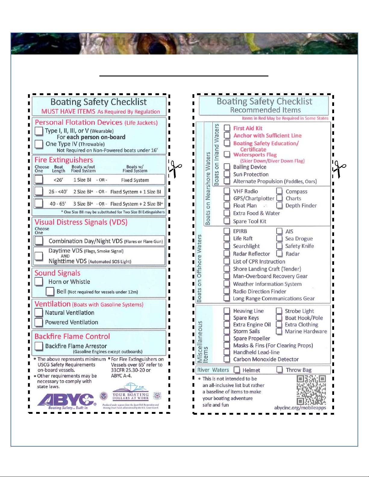
P R E - O P E R A T I O N C H E C K L I S T
*******PRE OPERATION CHECK LIST*******
(we recommend that you remove the checklist and store at the helm station)

4
M a v e r i c k B o a t C o m p a n y , I n c . •3207 I n d u s t r i a l 2 9 t h S t . •F o r t P i e r c e , F l o r i d a 34946 •( 7 7 2 ) - 465-0631 or
( 8 8 8 ) - s h a l l o w •F a x : ( 7 7 2 ) 489-2168
M A I N T E N A N C E & C L E A N I N G
Maintenance
Cobia advises owners that maintenance and repairs should be performed at an authorized Cobia dealer. The following
information is general in nature and should not be considered a repair manual or guidelines set forth by Maverick Boat
Company.
Cleaning
Each Cobia boat is constructed using the finest materials and components available. However, no material is immune to the
ravages of the saltwater environment. After each use, your boat should be rinsed thoroughly with fresh water. To clean the
cushions, use only a damp cloth. Never hose down or saturate the cushions. A mild detergent may also be used to remove
any dirt, silt or stains. A light coat of lubricant on metal railing, screws and electrical connections will help prevent electrolysis.
The same holds true for your trailer.
5
M a v e r i c k B o a t C o m p a n y , I n c . •3207 I n d u s t r i a l 2 9 t h S t . •F o r t P i e r c e , F l o r i d a 34946 •( 7 7 2 ) - 465-0631 or
( 8 8 8 ) - s h a l l o w •F a x : ( 7 7 2 ) 489-2168
E N G I N E B R E A K - IN P E R I O D
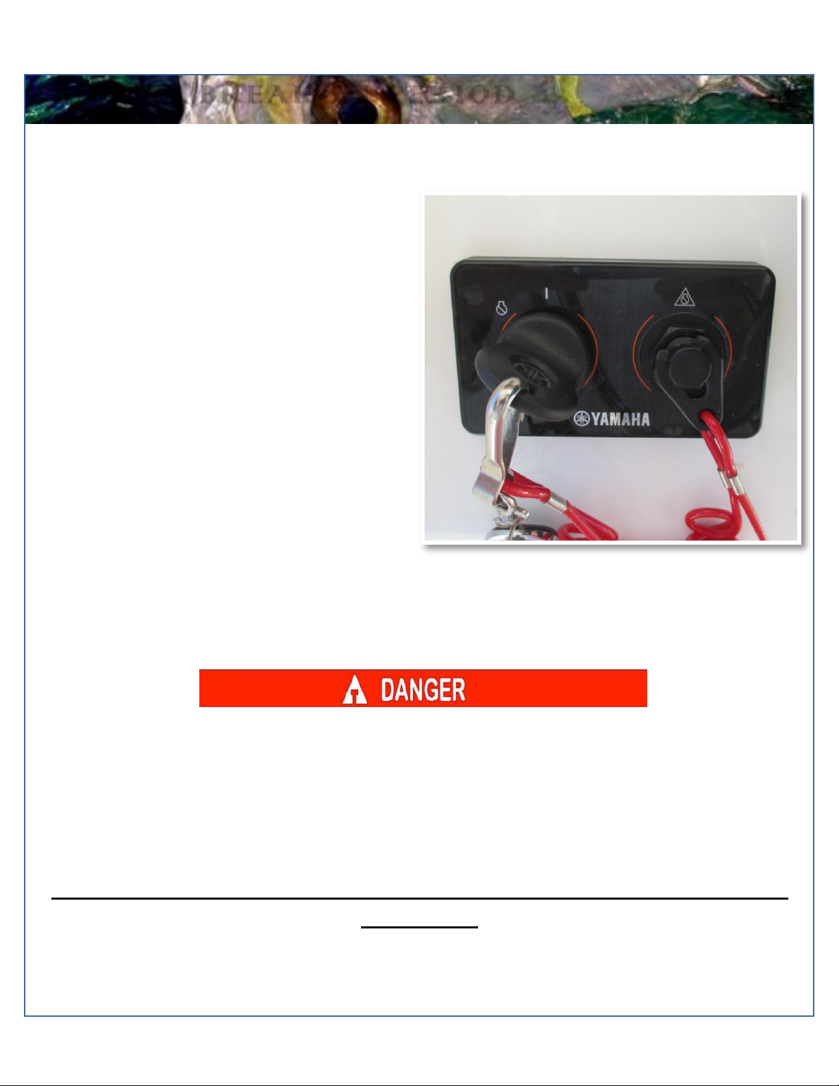
Engine stop switch (above)
Engine Break-In Period
New engines require a period of break-in to allow the
surfaces of the moving parts to mate evenly. Different
engines require different break-in periods and methods.
For instructions on break inmethods, refer toyour Yamaha
Engine Owner’s Manual for the correct break-in
procedures and times for your model engines
Engine Stop Switch
If activated, the spring-loaded engine stop switch will
automatically shut down the engine during emergency
situations to prevent uncontrolled or unattended operation.
Certain emergency conditions (e.g., turbulent water,
wakes, accidental shove) may impair a person’s ability to
operate the craft safely. The switch, located on the helm,
must have the safety lanyard attached at its base. This
activates the protective shutdown circuitry.
Securely attachthe other end of thelanyardtotheoperator
of the boat. If the operator moves, falls or is at an unsafe
distance from the steering wheel, tension on the lanyard
will pull it from the switch. When the lanyard is removed,
the engine stop switch is released and automatic engine
shutdown occurs.
Engine Stop Switch
An engine stop switch system that is not used or does not function properly can cause death or serious injury.
DO NOT operate the boat if the engine stop switch system does not function properly. Go to a Cobia Dealer to
have this resolved immediately
The lanyard should be securely attached to the boat operator at all times that the
engine is on.
6
M a v e r i c k B o a t C o m p a n y , I n c . •3207 I n d u s t r i a l 2 9 t h S t . •F o r t P i e r c e , F l o r i d a 34946 •( 7 7 2 ) - 465-0631 or
( 8 8 8 ) - s h a l l o w •F a x : ( 7 7 2 ) 489-2168
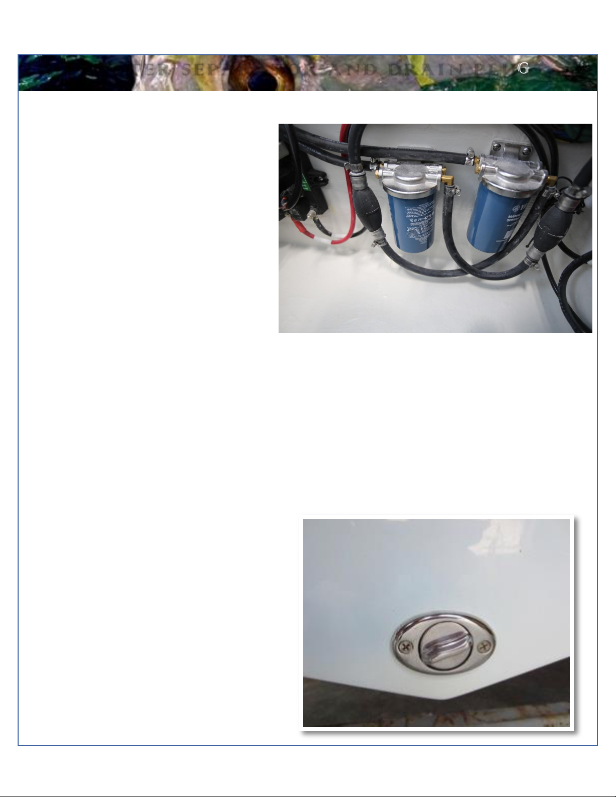
Fuel/Water Separator (above)
Fuel-Water Separator
Two Yamaha Fuel - Water Separators are installed
between the fuel tank and engine on your 280 model.
The new, improved 10-micron filter provides superior
filtration ahead of the engine's on- board filters and
injectors. Large filtering and water capture areas
maximize filtration while maintaining adequate flow
rate for larger engines. The fuel separator can be
checked by removing it from the mounting bracket
and dumping it into an approved waste collection
device. If there appears to be an excessive amount of
water, the filter component should be replaced. See
your authorized Cobia Dealer for replacement parts.
Refer to page 13 for the Fuel system diagram.
Maintenance Note
Yamaha recommends replacing the 10- micron fuel filter on new boats after the first 10 hours or 1 month of
operation and every 50 hours or every 6 months thereafter. In areas of high humidity where water in fuel supplies is a
problem or extensive engine operation occurs, more frequent replacement may be necessary.
Garboard Drain Plug
The garboard drain plug is the small metal plug located at
the lowest point on the hull, at the bottom of the transom
right above the keel. The drain has been designed to so
that it can be loosened by hand while the hull is out of the
water for draining. This allows the plug to stay in contact
with the surrounding frame so you’ll nevermisplace or lose
it. You can completely remove the insert by pulling back
and continue turning in a counter clockwise motion. It is
manufactured with a rubber seal in place to ensure you
bilge is watertight. Always make sure before putting the
boat in the water that this plug is hand tightened firmly.
Excess water inthe bilge may be anindicationof a problem
with this plug or the automatic bilge pump. Refer to page 9
of this Owner’s Manual for information on your boat’s bilge
system.
F U E L - W A T E R S E P A R A T O R A N D D R A I N P L U G
7
M a v e r i c k B o a t C o m p a n y , I n c . •3207 I n d u s t r i a l 2 9 t h S t . •F o r t P i e r c e , F l o r i d a 34946 •( 7 7 2 ) - 465-0631 or
( 8 8 8 ) - s h a l l o w •F a x : ( 7 7 2 ) 489-2168
S W I T C H A N D H E L M
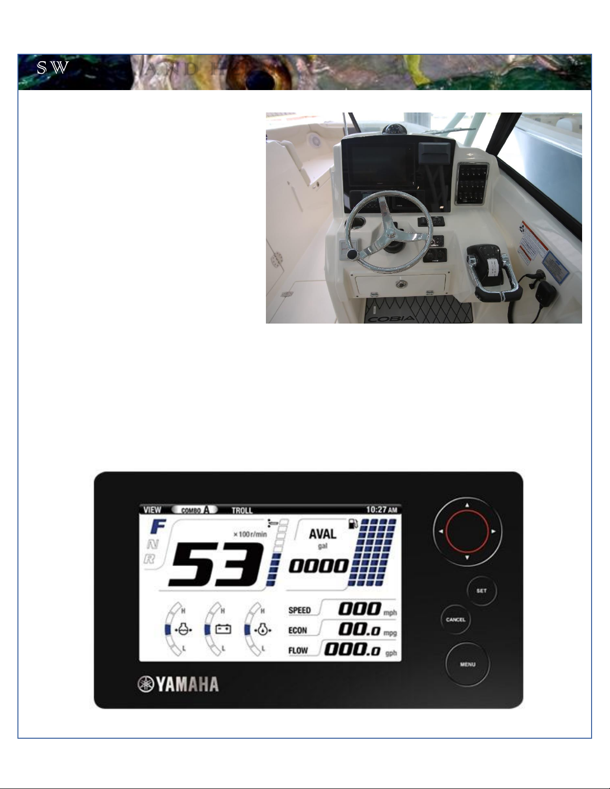
Switch Panel & Helm
At the helm of the 280 DC, you have a main switch
panel, which is located to the left of the steering
wheel. This panel controls your lights, horn,
accessories, livewell, and your bilge. When the
“NAV” light switch is in the “on” position, the labels
for the switches will be illuminated. To the right of
the steering wheel you may have your two trim tab
switches, which are standard on the 280. (Refer to
page 22 for trim tab operation.)
Switch Panel
Command Link Gauges
Yamaha’s new6YCCommandLinkgauge comesstandardon your newCobia. Thisgauge allowsaccessto moreinformation
and is user-selectable so you can choose the functions displayed. Speed data can be displayed from a pitot tube, Triducer,
or NMEA protocol GPS unit. To learn the gauge’s full functionality, refer to your Yamaha engine owner’s manual located in
the Cobia duffel bag.
8
M a v e r i c k B o a t C o m p a n y , I n c . •3207 I n d u s t r i a l 2 9 t h S t . •F o r t P i e r c e , F l o r i d a 34946 •( 7 7 2 ) - 465-0631 or
( 8 8 8 ) - s h a l l o w •F a x : ( 7 7 2 ) 489-2168
B O A T L A Y O U T
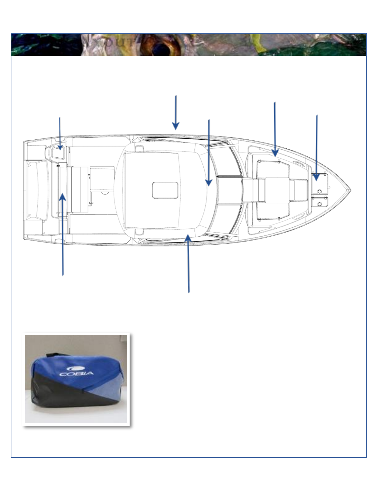
Cobia 280 Duffel Bag
Cobia Duffel Bag
Along with your boat, you received a blue Duffel Bag with your new Cobia 280
DC. Inside the Duffel Bag are the following items:
•Large Livewell Standpipe
•Short Livewell Standpipe
•1.5” Livewell Pacifier Plug
•2 ignition Keys and Emergency Kill Cord /Engine Stop Lanyard
•Yamaha Engine Owner’s Manuals
•Engine Start Cord
•Various Accessories Manuals
280DC Boat Layout
Console (under
hard top)
Livewell
Ski Box (under hard
top)
Bow Seating
Anchor Locker
Bilge Access
Fuel Fill
9
M a v e r i c k B o a t C o m p a n y , I n c . •3207 I n d u s t r i a l 2 9 t h S t . •F o r t P i e r c e , F l o r i d a 34946 •( 7 7 2 ) - 465-0631 or
( 8 8 8 ) - s h a l l o w •F a x : ( 7 7 2 ) 489-2168
B I L G E
Bilge
The bilge of the Cobia 280 should always be checked before and after a launch. While checking the bilge, note that a small
amount of water in the bilge is normal. However, a large amount of water or any signs of fuel or oil requires immediate
attention. If such a situation exists, the boat should be taken to a certified marine technician immediately. Never
pump fuel or oil overboard while your boat is in the water.
Large quantities of water in the bilge may be an indication of a leak or that the bilge pump and/or automatic float switch is
not functioning properly due to a jam, clog or electrical issue. The automatic float switch is wired to the hot side of the battery
switch through the “BILGE” fuse at the battery switch panel. When functioning properly, the float switch activates the bilge
pump to pump water overboard once water in the bilge reaches a level that submerges the switch.
If your bilge pump does not come on when the float switch is submerged, attempt to manually turn on the bilge pump on
your switch panel. If the bilge pump comes on and evacuates the water, it is clear that the float switch is not functioning
properly. If the bilge pump does not come on via the switch panel, check the breaker panel inside the console to see if a
breaker has been tripped. If the breaker has been tripped, reset it, and turn the switch on again, listening for the bilge pump
to turn on. Additionally, the automatic float switch has an independent fuse located by the batteries.
If the bilge pump fails to turn on, turn the battery switch to the OFF position, then unhook the bilge pump from its cradle
by pressing down on the blue tabs on the cradle and gently turning the top of the pump. You will feel the pump release
from the cradle. The entire bilge pump and wiring should release from the cradle. After removing the pump, check the
underside and impeller areas for miscellaneous items that might clog the pump. If any obstructions are present remove
the debris and set the pump back into the cradle. Once set back in the cradle, press the blue tab down and rotate the
pump until you feel it snap back in place. Once this is completed you can try to turn the pump on again.
If the bilge pump still does not turn on, it likely needs to be replaced. It is not recommended to use your boat if the bilge
pump and/or float switch are not functioning properly.
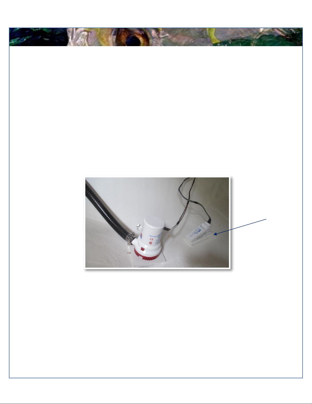
NOTICE. Your bilge pump is equipped with an anti-airlock nozzle that exhausts any air that may cause the pump to air
lock. It is normal to see mist or spray escaping while the pump is running as it is still functioning properly.
Bilge Pump and Float Switch

10
M a v e r i c k B o a t C o m p a n y , I n c . •3207 I n d u s t r i a l 2 9 t h S t . •F o r t P i e r c e , F l o r i d a 34946 •( 7 7 2 ) - 465-0631 or
( 8 8 8 ) - s h a l l o w •F a x : ( 7 7 2 ) 489-2168
S Y S T E M S
THE LIVEWELL PUMP
ASSEMBLY IN THE “OPEN
POSITION
Ball Valves
Ball valves can be used to serve several purposes. They
allow seawater to enter the boat, in the case of livewells,
and they also act as a safeguard to stop water from
entering. To tell which position a ball valve is in, open or
closed, look at the valve and determine the direction of
flow. When the ball valve handle isin the same position as
the direction of flow, the valve is in the “OPEN” position.
When the ball valve handle appears to cross the direction
of flow, the valve is in the “CLOSED” position.
280 Deck Drain System
The deckdrain system is equipped with 1 1/2” thru hull
fittings through the aft port and starboard hull sides. These
fittings have to be installed lower than the drains in the
cockpit floor so that gravity will allow the cockpit to drain
freeof water. Thisputsthese fittingsveryclose to thewater
lineof the hull. These drains are rigged with ball valves that
can be opened and closed to control the flow of water. The
ball valves can be accessed through the pie eyes on the
port starboard side of the transom. In the open position,
these ball valves will allow water to flow freely from the
cockpit, thus making the boat “self-bailing”. When closed,
no water will be allowed to travel to or from the cockpit.
Refer to page 34 for the Deck Drain System Diagram.
280 Livewell Pump Assembly
The livewell pump assembly is composed of a scoop
strainer mounted tothe bottom of the hull, a thru hull fitting,
ball valve assembly, and the pump. As you can see, the
ball valve assembly is in the “OPEN” position. This is the
correct position for the operation of the livewell system.
Water Flow
OPEN

11
M a v e r i c k B o a t C o m p a n y , I n c . •3207 I n d u s t r i a l 2 9 t h S t . •F o r t P i e r c e , F l o r i d a 34946 •( 7 7 2 ) - 465-0631 or
( 8 8 8 ) - s h a l l o w •F a x : ( 7 7 2 ) 489-2168
C O C K P I T C O U R T E S Y L I G H T S
Diagram of the LED Cockpit Courtesy Lights
Cockpit Courtesy Lights
The cockpit comes equipped with three L.E.D. courtesy lights installed at
the factory. On the switch panel located to the left of the steering helm,
the second switch to the right operates the cockpit courtesy lights. The
courtesy lights are mounted on the port and starboard sides of the
console, as well as at the front of the cockpit. These lights illuminate the
entire cockpit.
LED Cockpit Light

12
M a v e r i c k B o a t C o m p a n y , I n c . •3207 I n d u s t r i a l 2 9 t h S t . •F o r t P i e r c e , F l o r i d a 34946 •( 7 7 2 ) - 465-0631 or
( 8 8 8 ) - s h a l l o w •F a x : ( 7 7 2 ) 489-2168
L A D D E R A N D P R O P S
P R O P S
Props
Prop selection on your Cobia is determined by your local
Cobia Dealer, but all props are based on
recommendationsfrom Cobia Boat Company and Yamaha
Marine in order to give your boat maximum overall
performance. The needs of your prop will determine the
prop design and size that best fits your performance
requirements.
Always inspect the engine and prop prior to launching your
boat with the engine off. Key prop issues include tangled
fishing line or other types of debris, cracked blades or fluid
leaking out of the seal. Look for fishing line tangled around
the prop or lower unit seal. Consult your Yamaha’s
Owner’s Manual to address these issues.
No passenger should attempt to enter or exit the boat by the ladder or by any other means
while the engine is on.
Stainless Boarding Ladder
The 280 model comes standard with a telescoping stainless-steel
boarding ladder integrated into the port aft platform area. This provides
a stepping area while the ladder is in the up position as shown below.

13
M a v e r i c k B o a t C o m p a n y , I n c . •3207 I n d u s t r i a l 2 9 t h S t . •F o r t P i e r c e , F l o r i d a 34946 •( 7 7 2 ) - 465-0631 or
( 8 8 8 ) - s h a l l o w •F a x : ( 7 7 2 ) 489-2168
CAUTION—Do not smoke while filling the tank. Be sure to turn off the engines and all electrical
equipment when fueling the boat to prevent accidental discharges of static electricity. Use only the
recommended gasoline (see Yamaha’s Owner’s Manual). Do not use fuels with alcohol or alcohol
related derivatives that can cause marine fuel system hoses to deteriorate. Be sure to inspect all
fuel connections annually for signs of leaks or loose fittings.
F U E L S Y S T E M
FUEL SYSTEM
The Cobia 280 DC comes equipped with a 172 gallon fuel
cell between the stringer system. The fuel fill receptacle is
on the port gunnel. Every fuel tank is pressure tested at the
factory before and after installation. Should you experience
any fuel related problems or suspect problems with the fuel
system, immediately take your boat to a Cobia Dealer.
14
M a v e r i c k B o a t C o m p a n y , I n c . •3207 I n d u s t r i a l 2 9 t h S t . •F o r t P i e r c e , F l o r i d a 34946 •( 7 7 2 ) - 465-0631 or
( 8 8 8 ) - s h a l l o w •F a x : ( 7 7 2 ) 489-2168
S E L F - B A I L I N G C O C K P I T & A N C H O R S Y S T E M
Self-Bailing Cockpit
The cockpit on the Cobia280 isdesigned tobe self-bailing,
meaning that all the water that comes into the cockpit will
be directly drained overboard. This keeps the boat from
acquiring standing water and allows the boat to drain at all
times, including while the boat is docked.
Water drains into the fish boxes on either side of the rear
deck space and then drains overboard through the side of
the hull independently. None of this water is drained into
the bilge. Refer to page 8 for operation of the ball valve
associated with this system.
The bilgeisdesigned to drain any water enteringtheinside
of the hull. All hoses are sealed and double clampedduring
construction. Continuous or periodic running of the
automatic bilge pump may be an indication of a hose leak
or break in a seal, and should be investigated by a Cobia
Dealer immediately. Refer to page 9 for further information
regarding bilge pump operationand maintenance. You can
also refer to page 34 for the Deck Draining System.
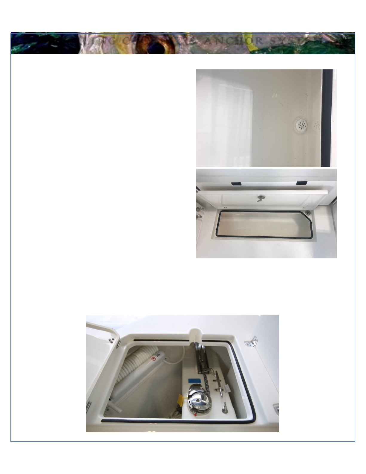
Anchor Locker/Rode Storage
The anchor locker is located at the bow of the boat and is accessible through the anchor locker door or hatch. There is an
eye mounted to the bow eye to secure your anchor rode or chain to. After setting your anchor, the excess rode can remain
stored in the locker. The notch supplied in the door allows you to securely close the locker by aligning your rode through
the notch.
15
M a v e r i c k B o a t C o m p a n y , I n c . •3207 I n d u s t r i a l 2 9 t h S t . •F o r t P i e r c e , F l o r i d a 34946 •( 7 7 2 ) - 465-0631 or
( 8 8 8 ) - s h a l l o w •F a x : ( 7 7 2 ) 489-2168
W I N D S H I E L D
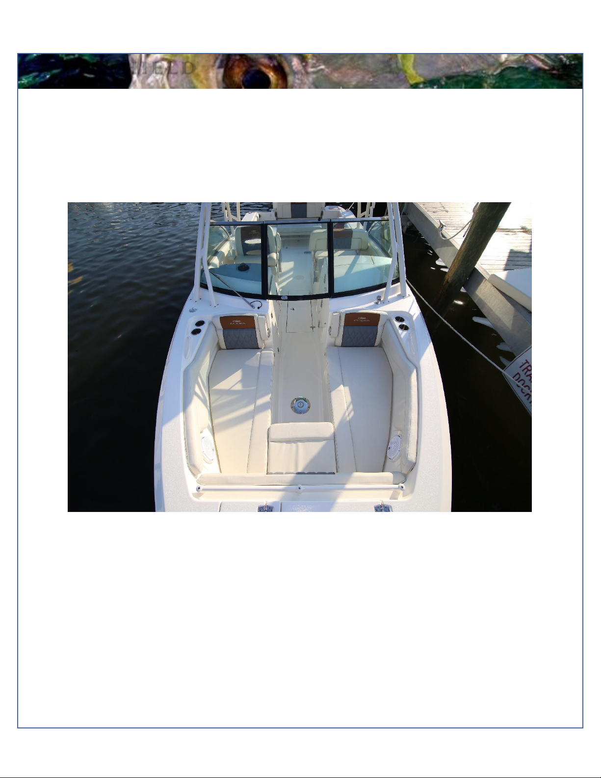
Windshield
The windshield on the 280 DC can fold to either fit in either an open or closed position. The open position allows for an easy
walkway to and from the bow. Use the tabs on the walkthrough glass panel to secure it closed to the other side in the event
of rough water or while trailering.
16
M a v e r i c k B o a t C o m p a n y , I n c . •3207 I n d u s t r i a l 2 9 t h S t . •F o r t P i e r c e , F l o r i d a 34946 •( 7 7 2 ) - 465-0631 or
( 8 8 8 ) - s h a l l o w •F a x : ( 7 7 2 ) 489-2168
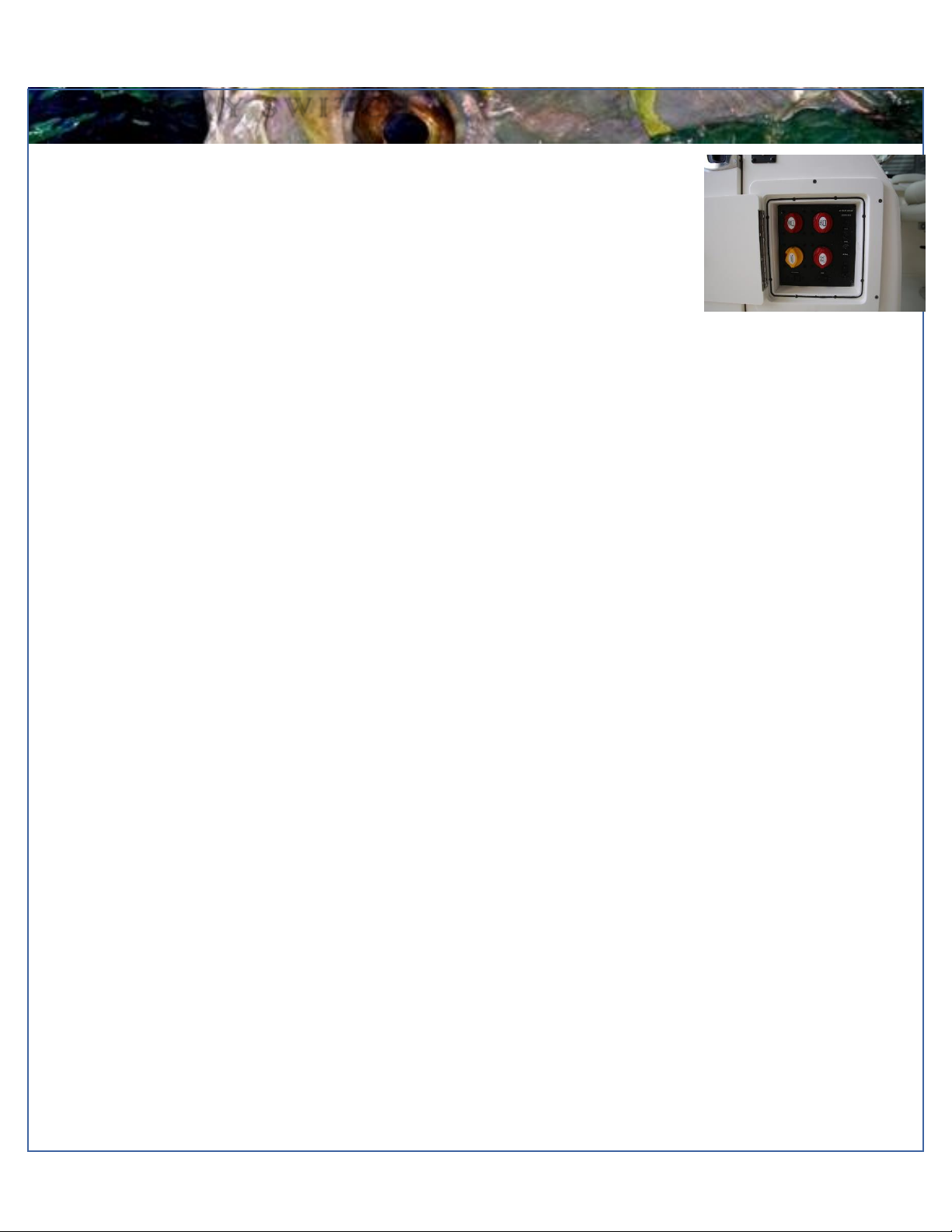
B A T T E R Y S W I T C H
Battery Switch (Shown In
Off Position)
Battery Switch and Main Distribution Panel
The battery switches and main distribution panel are located on the inboard wall of the helm
station. The battery switches are labeled to correspond with each battery and the component
it powers. Each engine has its own battery and there is a house battery that powers the boat’s
other electrical systems. Inthe event that thereisa second house battery on board, this battery
will be tied to the house battery switch. The “emergency parallel” switch parallels the two
cranking batteries and should only be used to crank the engines if one of the engine cranking
batteries does not have sufficient power to crank its associated engine. When the boat is not
being used for a prolonged period, it is recommended to leave all battery switches in the “off”
position to ensure that the batteries are not drained due to minor current flows.
The forward and aft bilge pumps and stereo memory breakers, located at the top right of the
panel, are on 24 hour circuits and will receive power at all times even with the house battery
switch in the off position. This ensures that the bilge pumps and float switches will remain
operational at all times unless the house battery loses all power. There is an additional 24 hour
circuit with a 15 amp breaker labeled “ACC” left open for adding an accessory appropriate to
24 hour operation. To reset any of these breakers simply push in the button associated with
the involved component.
Directly below the 24 hour “ACC” breaker is the windlass breaker. This is a gate style breaker.
When the circuit is open or the breaker is “popped”, a yellow tab will show in the recess just
below the bar with the red button. Simply push the free end of the yellow tab back up inside
the bar until it catches. The circuit is now closed and the windlass should be receiving power
from the house battery. To open the circuit, simply press the red button.
At the bottom of the distribution panel and to the left of the windlass breaker are the breakers
for the power steering, electronics, helm panel, stereo amp (if applicable) and aft hatch. All
these components run off the house battery (s). If popped these breakers will show red in the
window below the “Off“ label on the left side of the switch. To reset push in the right side of the
switch, “ON”, so that it is flush with the panel.
The bottom right breaker, “ACC”, is a 50 amp breaker left open for adding an appropriate 50
amp accessory.
It is important that all breakers match the amperage requirements of their associated
components. The back of the breakers are labeled with their amperages and can be viewed
by looking at the back of the panel as accessed through the battery access door on the front
of the leaning post.
Access to these breakers can be found through the battery access door. (see page 27)
17
M a v e r i c k B o a t C o m p a n y , I n c . •3207 I n d u s t r i a l 2 9 t h S t . •F o r t P i e r c e , F l o r i d a 34946 •( 7 7 2 ) - 465-0631 or
( 8 8 8 ) - s h a l l o w •F a x : ( 7 7 2 ) 489-2168
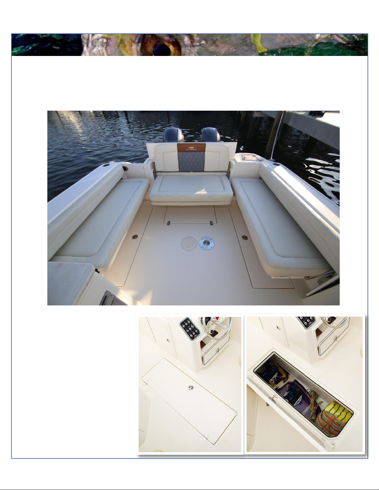
A F T B E N C H A N D S K I B O X
Aft Bench Seat
The Cobia 280 DC has an innovative aft bench which can be positioned two different ways. In the compact position, the seat
leaves more room on the deck by resting the bottom cushion in a vertical position. While in this position, the transom is made
more easily accessible. While in the upright position, the bench provides enough space to seat multiple passengers comfortably.
Ski Locker
To allow for maximum efficiency of space,
the Cobia 280 DC features a compartment
built into the floor of the boat, port of the
helm. It can hold an array of items due to
the large amount of space it offers while
still allowing for easy movement around
the deck over top of it. This box drains into
the bilge.
18
M a v e r i c k B o a t C o m p a n y , I n c . •3207 I n d u s t r i a l 2 9 t h S t . •F o r t P i e r c e , F l o r i d a 34946 •( 7 7 2 ) - 465-0631 or
( 8 8 8 ) - s h a l l o w •F a x : ( 7 7 2 ) 489-2168
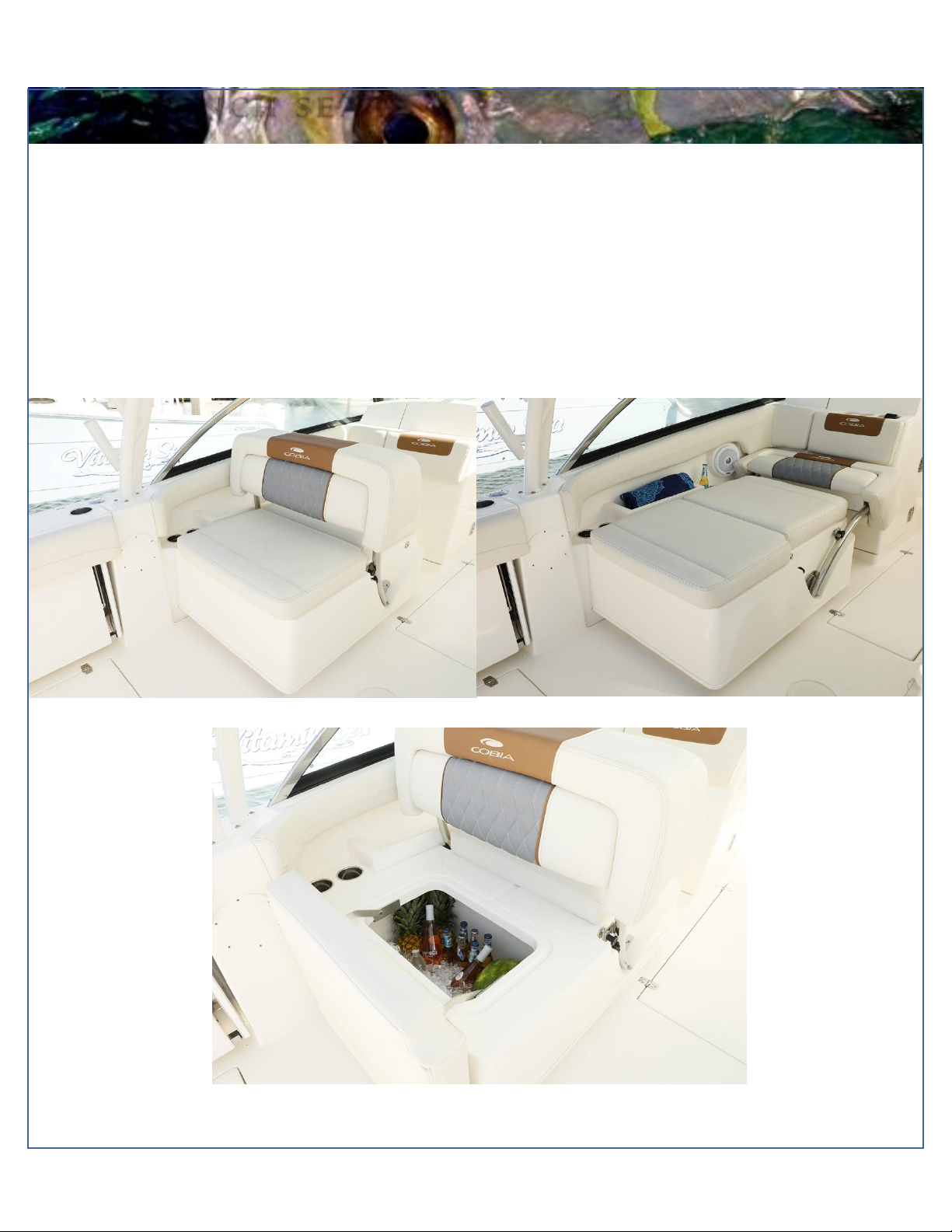
A F T B E N C H S E A T
Cooler Bench Seat
Your Cobia 280 DC comes equipped with a versatile and easy to use adjusting cooler seat. It can be positioned to provide a
front facing seat or a reclined back facing seat. The position of the seat can be changed by simply by moving the backrest
opposite the direction you would like to face. The bottom cushion can also be lifted to allow access to a cooler. Store drinks and
refreshments in the cooler to keep them ice cold throughout the day on the water. In addition, this system includes a fold-down
back-rest. To bring the back-rest into the upright position, simply grab the cushion near the end and lift up until it locks in the
horizontal position. Tolower the cushion, locate the finger pull pin found on the starboard side of the bottom of the back-rest and
pull out to release and lower the back-rest into the vertical position. The pin will lock when the backrest is in the correct position.

19
M a v e r i c k B o a t C o m p a n y , I n c . •3207 I n d u s t r i a l 2 9 t h S t . •F o r t P i e r c e , F l o r i d a 34946 •( 7 7 2 ) - 465-0631 or
( 8 8 8 ) - s h a l l o w •F a x : ( 7 7 2 ) 489-2168
O P T I O N A L F E A T U R E S
Optional Features
Many options for the 280 Dual Console model have already been mentioned earlier in the Owner’s Manual. The following
pages will refer to the remaining options.
20
M a v e r i c k B o a t C o m p a n y , I n c . •3207 I n d u s t r i a l 2 9 t h S t . •F o r t P i e r c e , F l o r i d a 34946 •( 7 7 2 ) - 465-0631 or
( 8 8 8 ) - s h a l l o w •F a x : ( 7 7 2 ) 489-2168
\
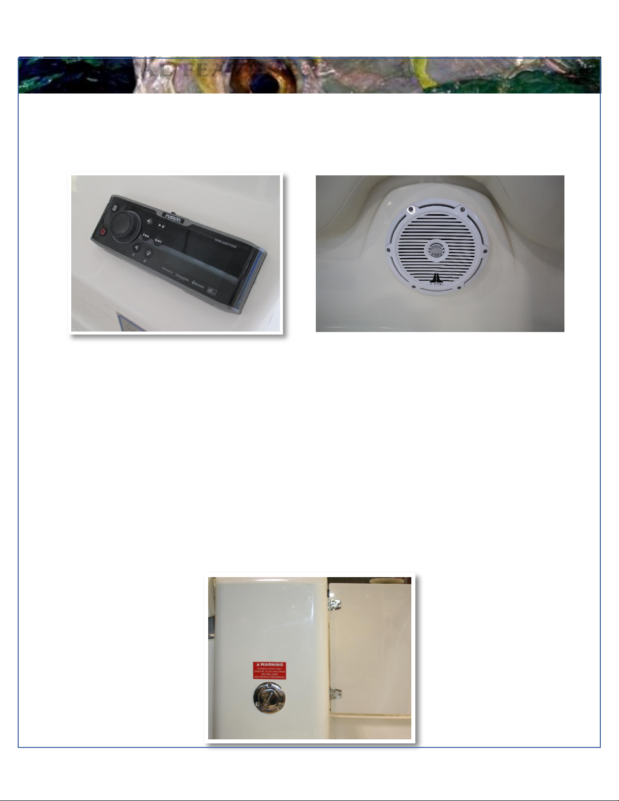
O P T I O N A L F E A T U R E S
Optional JL Audio Stereo System
A JL Audio stereo system with eight JL speakers is offered as an option on the 280 DC. The Media Master100 (MM100) head
unit is paired with a M800/8v2 stereo amplifier. The amplifier is installed inside the starboard console and the head unit is
mounted on the helm.
Stereo Unit
Fresh Water Washdown
The fresh water tank on your 280 DC can be filled at the cap labeled “WATER”, on the starboard transom next to the walk-thru
door. The shower nozzle is on the starboard aft bulkhead. To pressurize the system, flip the switch labeled “FRESHWATER”
on the switch panel at the helm. You can leavethis switch in the ON position while the boat isin use. The pump has an internal
pressure switch that allows the pump to turn on and off as needed. (Refer to page 35 for the 280 DC water supply diagram.)
In the colder months of the year, it’s advisable to drain the fresh water system and winterize by adding a non-toxic antifreeze
to the system. Run the antifreeze through the system by opening up the spray in the shower nozzle until antifreeze is delivered
through the showerhead.
JL Speaker System
This manual suits for next models
1
Table of contents
Other COBIA Boat manuals

COBIA
COBIA 262 CC User manual

COBIA
COBIA 240 CC User manual

COBIA
COBIA 296 CC 2014 User manual

COBIA
COBIA 2016 277 CC User manual

COBIA
COBIA 350 CC User manual

COBIA
COBIA 280 DC User manual

COBIA
COBIA 237 CC 2014 User manual

COBIA
COBIA 330 DC User manual

COBIA
COBIA 320 CC User manual

COBIA
COBIA 217 CC User manual


Popular Boat manuals by other brands


Jeanneau
Jeanneau SUN ODYSSEY 41 DS owner's manual

Meridian
Meridian 490 Pilothouse owner's manual

Advanced Elements
Advanced Elements AdvancedFrame Expedition AE1009 owner's manual

Robo Marine Indonesia
Robo Marine Indonesia GEOMAR user manual

Swallow Boats
Swallow Boats BayRaider owner's manual

X SHORE
X SHORE EELEX 8000 owner's manual


