2
TABLE OF CONTENTS
TABLE OF CONTENTS ................................................................................................................................................ 2
CONGRATULATIONS ................................................................................................................................................. 3
SAFETY ..................................................................................................................................................................... 3
SYMBOL GLOSSARY .................................................................................................................................................. 4
SPECIFICATIONS (SUBJECT TO CHANGE WITHOUT NOTICE) ...................................................................................... 5
EQUIPMENT LOCATION ............................................................................................................................................ 6
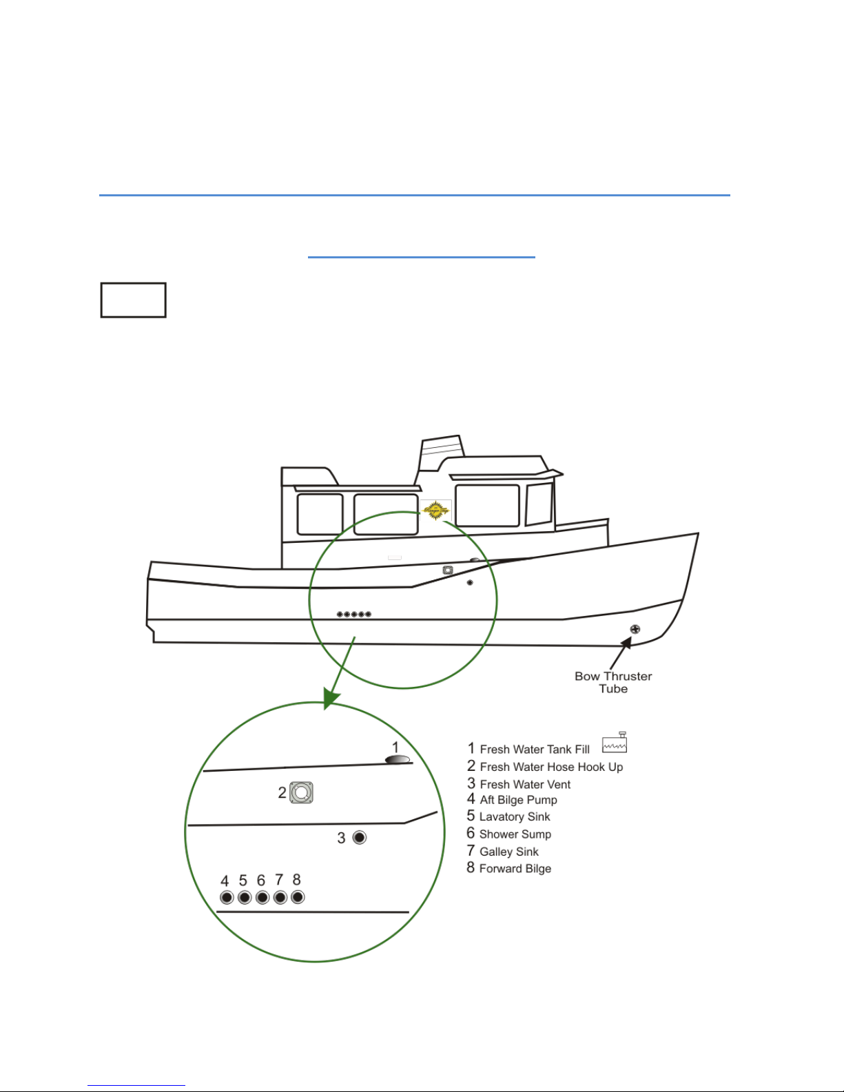
STARBOARD FITTINGS .......................................................................................................................................... 6
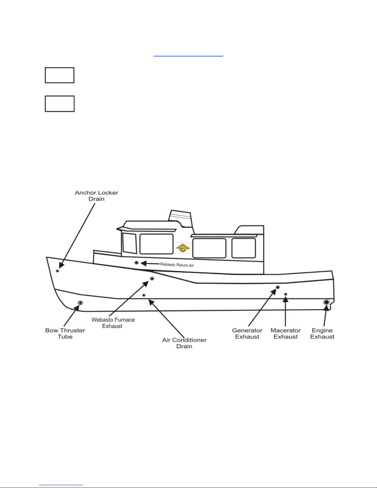
PORT FITTINGS..................................................................................................................................................... 7
MAIN CABIN TOP DECK COMPONENTS ................................................................................................................. 8
STERN COMPONENTS........................................................................................................................................... 9
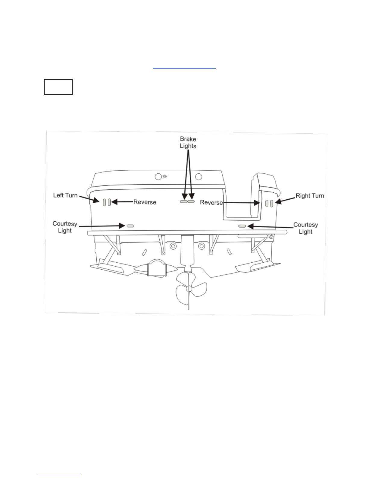
STERN LIGHTS .................................................................................................................................................... 10
AVAILABLE STORAGE.......................................................................................................................................... 11
FUSE LOCATION &VALUES ................................................................................................................................. 12
MAIN CABIN AND COCKPIT LIGHTS ..................................................................................................................... 13
BATTERY COMPARTMENT .................................................................................................................................. 14
POWER DISTRIBUTION PANEL (P.D.P) ................................................................................................................ 15
DC DISTRIBUTION PANEL, DC BANK METER, HEATER CONTROL........................................................................... 16
AC DISTRIBUTION PANEL &ROTARY SWITCH ...................................................................................................... 17
FUEL SYSTEM, ENGINE, GENERATOR &WEBASTO FURNACE ............................................................................... 18
CLOSED ENGINE COOLING SYSTEM..................................................................................................................... 19
SEA STRAINER SYSTEM ....................................................................................................................................... 20
RAW WATER WASH DOWN ................................................................................................................................ 21
FRESH WATER PLUMBING SYSTEM ..................................................................................................................... 22
SHOWER SUMP .................................................................................................................................................. 23
BILGE PUMP SYSTEM.......................................................................................................................................... 24
WASTE SYSTEM .................................................................................................................................................. 25
WASTE SYSTEM WITH MACERATOR PUMP ......................................................................................................... 26
MAST SET UP AND TAKEDOWN .......................................................................................................................... 27
RANGER TUG R-27 WIRING SCHEMATIC (ACC. 1) ................................................................................................ 28
RANGER TUG R-27 WIRING SCHEMATIC (ACC. 2) ................................................................................................ 29
RANGER TUG R-27 WIRING SCHEMATIC (ACC. 3) ................................................................................................ 30
RANGER TUG R-27 WIRING SCHEMATIC (LIGHTING) ........................................................................................... 31
RANGER TUG R-27 WIRING SCHEMATIC (P.D.P.) ................................................................................................. 32
RANGER TUG R-27 WORKING DECK ........................................................................................................................ 33
CARE AND MAINTENANCE ...................................................................................................................................... 34
EXAMPLE OF APREPARATION FOR THE ROAD CHECKLIST ................................................................................... 34
EXAMPLE OF ASPRING PRE-LAUNCH CHECKLIST................................................................................................. 35
EXAMPLE OF WINTER STORAGE CHECKLIST ........................................................................................................ 36
REFERENCE MATERIAL............................................................................................................................................ 37
CONTACTS .............................................................................................................................................................. 38