COBIA 320 CC User manual

1
Maverick Boat Group
3207 Industrial 29th St. • Fort Pierce, Florida 34946
(772)-465-0631 •cobiaboats.com
320 CC Owner’s Manual
Revised March 2020

2
Maverick Boat Group
3207 Industrial 29th St. • Fort Pierce, Florida 34946
(772)-465-0631 •cobiaboats.com
Dear New Cobia Owner,
On behalf of Cobia Boats, I would like to
congratulate you on your purchase. We at Cobia
strive to build the best products possible and wish
you years of trouble-free enjoyment. There are
many things to know about the operation, care,
and maintenance of our products and the systems
we install in them. Please review all the applicable
information for your new boat. The more you
know, the more you will enjoy your new Cobia.
Again, a heartfelt thank you from myself and the
whole Cobia Family.
Scott Deal
President and CEO

3
Maverick Boat Group
3207 Industrial 29th St. • Fort Pierce, Florida 34946
(772)-465-0631 •cobiaboats.com
Table of Contents
Cobia 320 CC Specifications.................................................................................................. 4
Cobia 320 CC Deck Layout.................................................................................................... 5
Pre-Operation Checklist .......................................................................................................... 6
Maintenance & Cleaning....................................................................................................... 7
Engine Break-In Period ............................................................................................................ 8
Helm & Command Link Gauges ............................................................................................ 9
Fuel-Water Separator & Drain................................................................................................10
Bilge .........................................................................................................................................11
Systems ....................................................................................................................................13
Battery Switch and Main Distribution Panel..........................................................................14
Ladder & Props .......................................................................................................................16
Fuel System..............................................................................................................................17
Self-Bailing Cockpit & Livewell ...............................................................................................18
Rod Storage & Fish Lockers ....................................................................................................19
Macerator Access & Operation............................................................................................20
Anchor Locker.........................................................................................................................21
Standard Features ..................................................................................................................21
Optional Features ...................................................................................................................28
Cobia 320 CC Hull Wire Harness............................................................................................32
Cobia 320 CC Deck Wire Harness.........................................................................................33
Cobia 320 CC Hardtop Wire Harness....................................................................................34
Cobia 320 CC Fuel System.....................................................................................................35
Cobia 320 CC Water Drain System .......................................................................................36
Cobia 320 CC Water Supply System.....................................................................................37
Cobia 320 CC Bunk Placements ...........................................................................................38
Cobia 320 CC Bunk Placements ...........................................................................................39
Upholstery Care & Cleaning Guide ......................................................................................40
Warranty..................................................................................................................................41

4
Maverick Boat Group
3207 Industrial 29th St. • Fort Pierce, Florida 34946
(772)-465-0631 •cobiaboats.com
Cobia 320 CC Specifications
L.O.A........................................................................................................................32’0”
BEAM......................................................................………………….….................10’ 03”
DRAFT..........................................................................................................................23”
WEIGHT W/O ENGINE.......................................................................................7,324 LBS.
FUEL CAPACITY..................................................................................................275 GAL.
DEADRISE @ TRANSOM....................................................................................21.5 DEG.
MAXIMUM H.P.............................................................................................................700
TRANSOM HEIGHT…………………………………..…...…….………………….. 25” TWINS
MAXIMUM CAPACITIES..........................................................10 PERSONS OR 1700 LBS
5
Maverick Boat Group
3207 Industrial 29th St. • Fort Pierce, Florida 34946
(772)-465-0631 •cobiaboats.com
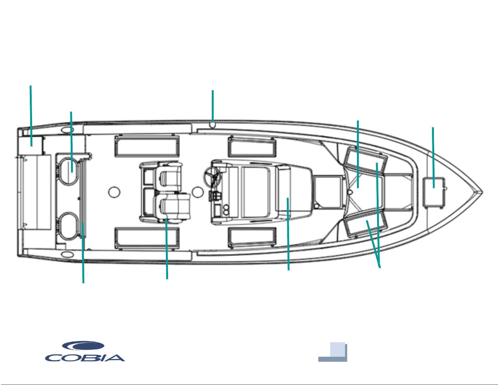
Livewell
Anchor Locker
Table Lift
Fuel Fill
Leaning Post/Tackle Station
Bilge Access
Storage Hatches
Boarding Ladder
Forward Console/Head
Entry
Cobia 320 CC Deck Layout

6
Maverick Boat Group
3207 Industrial 29th St. • Fort Pierce, Florida 34946
(772)-465-0631 •cobiaboats.com
Pre-Operation Checklist
We recommend you print this document and store it at the helm station.
7
Maverick Boat Group
3207 Industrial 29th St. • Fort Pierce, Florida 34946
(772)-465-0631 •cobiaboats.com
Maintenance & Cleaning
Maintenance
Cobia advises owners that maintenance and repairs should be performed at an
authorized Cobia Dealer. The following information is general in nature and should not
be considered a repair manual or guidelines set forth by Maverick Boat Group.
Cleaning
Each Cobia boat is constructed using the finest materials and components available.
However, no material is immune to the ravages of the saltwater environment. After each
use, your boat should be rinsed thoroughly with fresh water. Refer to page 40 for
upholstery care and cleaning instructions. A light coat of lubricant on metal railing,
screws and electrical connections will help prevent electrolysis. The same holds true for
your trailer.

8
Maverick Boat Group
3207 Industrial 29th St. • Fort Pierce, Florida 34946
(772)-465-0631 •cobiaboats.com
Engine Break-In Period
Engine Break-In Period
New engines require a period of break-in to allow the surfaces of the moving parts to
mate evenly. Different engines require different break-in periods and methods. For
instructions on break-in methods, refer to your Yamaha Engine Owner’s Manual for the
correct break-in procedures and times for your model engines.
Engine Stop Switch
If activated, the spring-loaded engine stop switch
will automatically shut down the engine during
emergency situations to prevent uncontrolled or
unattended operation. Certain emergency
conditions (e.g., turbulent water, wakes,
unanticipated movement) may impair a person’s
ability to operate the craft safely. The switch, located
on the helm, must have the safety lanyard attached
at its base. This activates the protective shutdown
circuitry.
Securely attach the other end of the lanyard to the operator of the boat. If the operator
moves, falls or is at an unsafe distance from the steering wheel, tension on the lanyard
will pull it from the switch. When the lanyard is removed, the engine stop switch is
released and automatic engine shutdown occurs.
Engine Stop Switch
DANGER:
An engine stop switch system that is not used or does not function
properly can cause death or serious injury. DO NOT operate the boat if
the engine stop switch system does not function properly. Go to a
Cobia Dealer to have this resolved immediately.
The lanyard should be securely attached to the boat operator at all times that
the engine is on.
9
Maverick Boat Group
3207 Industrial 29th St. • Fort Pierce, Florida 34946
(772)-465-0631 •cobiaboats.com
Helm & Command Link Gauges
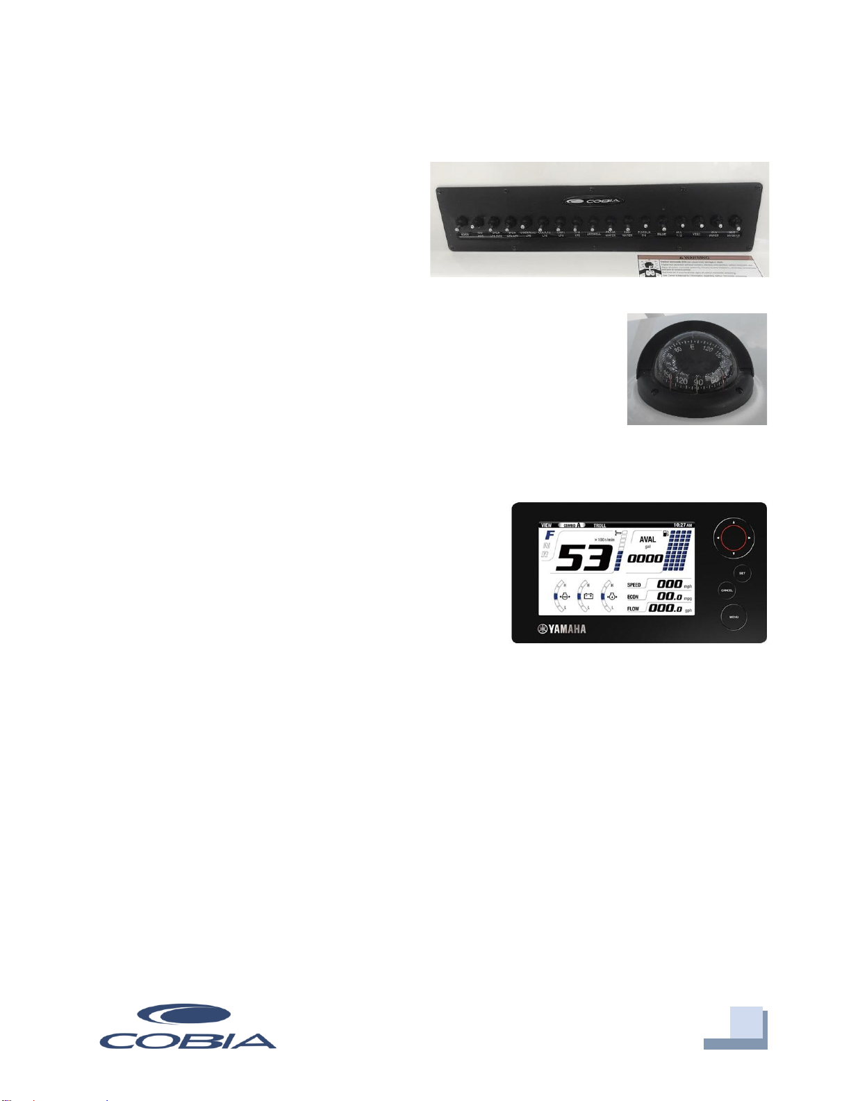
Switch Panel & Helm
At the helm of your Cobia, you have a main
switch panel, which is located to the left of
the steering wheel. This panel controls
your lights, horn, accessories, livewell, and
your bilge. When a switch is in the “on”
position, its tip is illuminated. This alerts you that the associated
accessory should be functioning and also reminds you to turn it off
during boat shutdown. When the “NAV” light switch is in the “on”
position, the labels for the switches will be illuminated. To the right
of the steering wheel you have your two trim tab switches. The boat
also comes standard with a compass mounted on top of the console.
Command Link Gauges
Yamaha’s new 6YC Command Link gauge comes
standard on your new Cobia. This gauge allows
access to more information and is user-selectable so
you can choose the functions displayed. Speed data
can be displayed from a pitot tube, Triducer, or
NMEA protocol GPS unit. To learn the gauge’s full
functionality, refer to your Yamaha engine owner’s
manual located in the Cobia Duffel Bag.
Cobia Duffel Bag
Along with your boat, you received a Duffel Bag with your new Cobia. Inside the Duffel
Bag are the following items:
oLarge Livewell Standpipe
oShort Livewell Standpipe
o1.5” Livewell Pacifier Plug
o2 ignition Keys and Emergency Kill Cord /Engine Stop Lanyard
oEngine Start Cord
oVarious Accessories Manuals
Switch Panel
Compass
Yamaha Command Link Gauge

10
Maverick Boat Group
3207 Industrial 29th St. • Fort Pierce, Florida 34946
(772)-465-0631 •cobiaboats.com
Fuel-Water Separator & Drain
Fuel-Water Separator
A Yamaha Fuel-Water Separator is installed behind the rear seat
assembly. Simply locate the controls for the electronic lift assist,
labeled “Hatch”, mounted on the starboard side of the tackle
station directly across from the gunwale, and you will be able to
easily access the Fuel-Water separator. The new, improved 10-
micron filter provides superior filtration ahead of the engine's
on-board filters and injectors. Large filtering and water capture
areas maximize filtration while maintaining adequate flow rate
for larger engines. The fuel separator can be checked by removing it from the mounting
bracket and dumping it into an approved waste collection device. If there appears to be
an excessive amount of water, the filter component should be replaced. See your
authorized Cobia Dealer for replacement parts.
Garboard Drain Plug
The garboard drain plug is the small metal plug located at
the lowest point on the hull, at the bottom of the transom
right above the keel. The drain has been designed so that it
can be loosened by hand while the hull is out of the water
for draining. This allows the plug to stay in contact with
the surrounding frame so you’ll never misplace or lose it. You can completely remove
the insert by pulling back and continue turning in a counter-clockwise motion. It is
manufactured with a rubber seal in place to ensure your bilge is watertight. Always
make sure before putting the boat in the water that this plug is hand tightened firmly.
Excess water in the bilge may be an indication of a problem with this plug or the
automatic bilge pump. (Refer to Water Drain System diagram, page 36).
Maintenance Note: Yamaha recommends replacing the 10-
micron fuel filter on new boats after the first 10 hours or 1 month of
operation and every 50 hours or every 6 months thereafter. In
areas of high humidity where water in fuel supplies is a problem or
extensive engine operation occurs, more frequent replacement
may be necessary.
Fuel-Water Separator
Drain Plug

11
Maverick Boat Group
3207 Industrial 29th St. • Fort Pierce, Florida 34946
(772)-465-0631 •cobiaboats.com
Bilge
Bilge Access
First, locate the controls on the electronic lift assist, labeled “Hatch”, mounted on the
starboard side of the tackle station directly across from the gunwale. Next, press and
hold the top button on the controls. This will cause the rear access to lift revealing the
bilge access. To lower the hatch simply press and hold the bottom button on the control
panel until the aft section is fully closed. Remember that the electronic lift assist
operates using the house battery system.
In the event that the boat does not have power to electronically lift the hatch, the
electronic lift can be disengaged by lowering the bench seat and using the access
opening shown below to remove the pin from the electronic ram. Keep in mind that at
this point the hatch will no longer be supported in the up position and will require being
held up to maintain access to the bilge. Once the work in the bilge is finished and power
is restored to the hatch lift, it is important to attach the ram to the hatch with the pin
once again to secure the door in the closed position.
Note: The aft seat backrest must be removed to fully open the hatch.
Failure to remove the backrest will result in damage to the backrest
and possibly the hatch lifting mechanism.
Hatch Control
Bilge Access
Electric Ram and Hatch Pin
12
Maverick Boat Group
3207 Industrial 29th St. • Fort Pierce, Florida 34946
(772)-465-0631 •cobiaboats.com
Bilge
The bilge of your Cobia should always be checked before and after a launch. While
checking the bilge, note that a small amount of water in the bilge is normal. However, a
large amount of water or any signs of fuel or oil
requires immediate attention. If such a situation
exists, the boat should be taken to a certified
marine technician immediately. Never pump
fuel or oil overboard while your boat is in the
water.
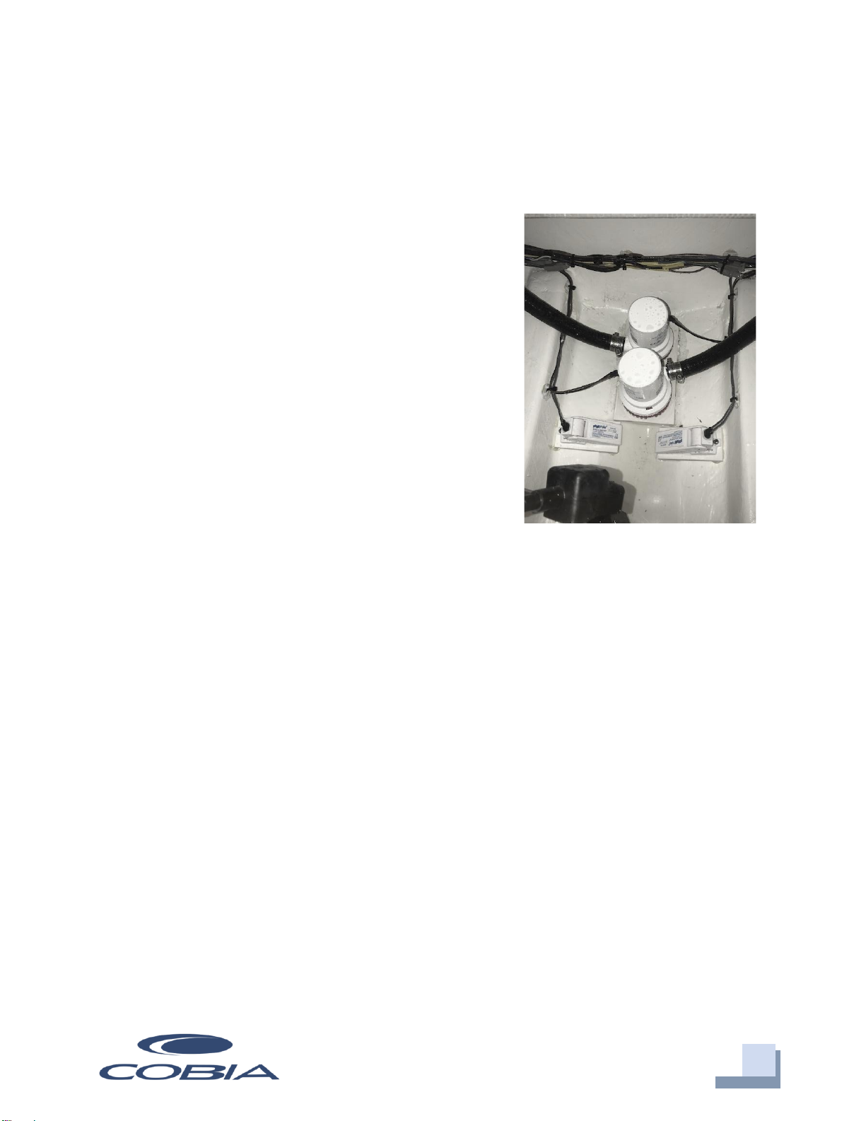
Large quantities of water in the bilge may be an
indication of a leak or that the bilge pump and/or
automatic float switch is not functioning properly due
to a jam, clog or electrical issue. The automatic float
switch is wired to the hot side of the battery switch
through the “BILGE” fuse at the battery switch panel.
When functioning properly, the float switch activates
the bilge pump to pump water overboard once water
in the bilge reaches a level that submerges the switch.
If the bilge pump does not come on when the float switch is submerged, attempt to
manually turn it on through your switch panel. If the bilge pump comes on and
evacuates the water, it is clear that the float switch is not functioning properly. If the
bilge pump does not come on via the switch panel, check the breaker panel inside the
console to see if a breaker has been tripped. If the breaker has been tripped, reset it and
turn the switch on again, listening for the bilge pump to turn on.
If the bilge pump fails to turn on, turn the battery switch to the OFF position, then
unhook the bilge pump from its cradle by pressing the locking tab and twist motor
housing counter-clockwise. You will feel the pump release from the cradle. The entire
bilge pump and wiring should release from the cradle. After removing the pump, check
the underside and impeller areas for miscellaneous items that might clog the pump. If
any obstructions are present remove the debris and set the pump back into the cradle.
Once set back in the cradle, press the pump down on the base then twist until the lock
button snaps it into place. Once this is completed you can try to turn the pump on again.
Bilge Pump and Float Switch
One Standard or Two Optional

13
Maverick Boat Group
3207 Industrial 29th St. • Fort Pierce, Florida 34946
(772)-465-0631 •cobiaboats.com
If the bilge pump still does not turn on, it likely needs to be replaced. It is not
recommended to use your boat if the bilge pump and/or float switch are not functioning
properly.
Systems
Ball Valves
Ball valves can be used to serve several purposes.
They allow seawater to enter the boat, in the case of
livewells, and they also act as a safeguard to stop
water from entering. To tell which position a ball
valve is in, open or closed, look at the valve and
determine the direction of flow. When the ball
valve handle is in the same position as the
direction of flow, the valve is in the “OPEN”
position. When the ball valve handle appears to
cross the direction of flow, the valve is in the
“CLOSED” position. The ball valves can be accessed
in the bilge compartment behind the aft seating.
320 Deckdrain System
The deckdrain system is equipped with 1 1/2” thru hull fittings through the aft port and
starboard hull sides. These fittings have to be installed lower than the drains in the
cockpit floor so that gravity will allow the cockpit to drain free of water. This puts these
fittings very close to the water line of the hull. These drains are rigged with ball valves
that can be opened and closed to control the flow of water. In the open position, these
ball valves will allow water to flow freely from the cockpit, thus making the boat “self-
bailing”. When closed, no water will be allowed to travel to or from the cockpit.
320 Livewell Pump Assembly
The livewell pump assembly is composed of a scoop strainer mounted to the bottom of
the hull, a thru hull fitting, ball valve assembly, and the pump. As you can see, the ball
valve assembly is in the “OPEN” position. This is the correct position for the operation
of the livewell.
14
Maverick Boat Group
3207 Industrial 29th St. • Fort Pierce, Florida 34946
(772)-465-0631 •cobiaboats.com
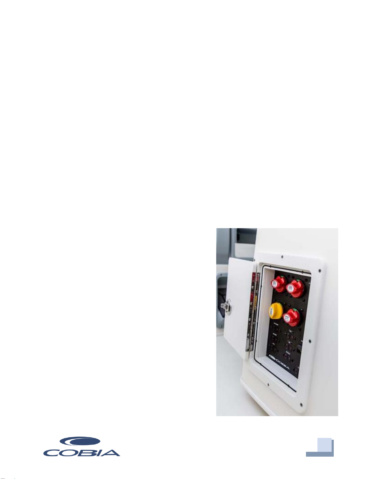
Battery Switch and Main Distribution
Panel
The battery switches and main distribution panel are located in the port compartment
on the side of the leaning post. The battery switches are labeled to correspond with each
battery and the component it powers. Each engine has its own battery and there is a
house battery that powers the boat’s other electrical systems. In the event that there is a
second house battery on board, this battery will be tied to the house battery switch. The
“emergency parallel” switch parallels the two cranking batteries and should only be used
to crank the engines if one of the engine cranking batteries does not have sufficient
power to crank its associated engine. When the boat is not being used for a prolonged
period, it is recommended to leave all battery switches in the “off” position to ensure
that the batteries are not drained due to minor current flows.
The forward and aft bilge pumps and stereo memory breakers, located at the top right of
the panel, are on 24-hour circuits and will receive
power at all times even with the house battery
switch in the off position. This ensures that the bilge
pumps and float switches will remain operational at
all times unless the house battery loses all power.
There is an additional 24-hour circuit with a 15-amp
breaker labeled “ACC” left open for adding an
accessory appropriate to 24-hour operation. To
reset any of these breakers simply push in the
button associated with the involved component.
Directly below the 24-hour “ACC” breaker is the
windlass breaker. This is a gate style breaker. When
the circuit is open or the breaker is “popped”, a
yellow tab will show in the recess just below the bar
with the red button. Simply push the free end of the
yellow tab back up inside the bar until it catches.
The circuit is now closed and the windlass should be
receiving power from the house battery. To open the
circuit, simply press the red button.
Battery Switch

15
Maverick Boat Group
3207 Industrial 29th St. • Fort Pierce, Florida 34946
(772)-465-0631 •cobiaboats.com
At the bottom of the distribution panel and to the left of the windlass breaker are the
breakers for the forward table, power steering, electronics, helm panel, stereo amp (if
applicable) and aft hatch. All these components run off the house battery (s). If popped
these breakers will show red in the window below the “OFF” label on the left side of the
switch. To reset push in the right side of the switch, “ON”, so that it is flush with the
panel.
The bottom right breaker, “ACC”, is a 50-amp breaker left open for adding an
appropriate 50-amp accessory.
It is important that all breakers match the amperage requirements of their associated
components. The back of the breakers are labeled with their amperages and can be
viewed by looking at the back of the panel as accessed through the battery access door
on the front of the leaning post.
Battery Access
All the batteries can be accessed by opening the door below the helm seat. Your boat
will have a house battery (or two) that operates the general electrical features of the boat
and a battery for each engine. Each battery should be able to be identified by the labels
on the wires that lead to it. When replacing batteries, it is critical the wires be secured to
the proper terminals precisely as they were on the previous battery(s).
Open Battery Access
16
Maverick Boat Group
3207 Industrial 29th St. • Fort Pierce, Florida 34946
(772)-465-0631 •cobiaboats.com
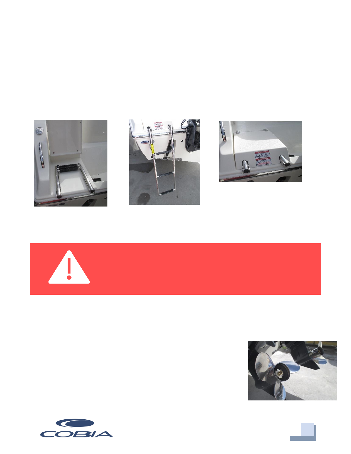
Ladder & Props
Stainless Boarding Ladder
This Cobia model comes standard with a telescoping stainless-steel boarding ladder
integrated into the port aft platform area. This provides a stepping area while the ladder
is in the up position as shown below. Once the ladder is down and in the extended
position, close the lid cover for safe and secure entry and exit via the ladder.
When washing off your boat at the end of the day make sure to extend the ladder and
wash it off, as well. Leaving saltwater in the telescoping tubes may lead to corrosion and
affect the useful life of your ladder.
Props
Prop selection on your Cobia is determined by your local Cobia Dealer, but all props are
based on recommendations from Cobia Boat Company and Yamaha Marine in order to
give your boat maximum overall performance. The needs of your
prop will determine the prop design and size that best fits your
performance requirements. Always inspect the engine and prop
prior to launching your boat with the engine off. Key prop issues
include tangled fishing line or other types of debris, cracked
blades or fluid leaking out of the seal. Look for fishing line
tangled around the prop or lower unit seal. Consult your
Yamaha Owner’s Manual to address these issues.
DANGER:
No passenger should attempt to enter or exit the boat by
the ladder or by any other means while the engine is on.
Engine Prop
17
Maverick Boat Group
3207 Industrial 29th St. • Fort Pierce, Florida 34946
(772)-465-0631 •cobiaboats.com
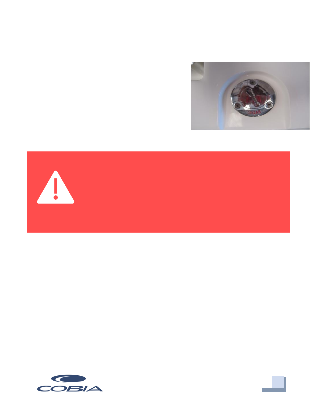
Fuel System
Fuel System
This Cobia comes equipped with a 275-gallon fuel cell
stationed below the leaning post between the stringer
system. The fuel fill receptacle is on the port gunwale.
Every fuel tank is pressure tested at the factory before
and after installation. Should you experience any fuel
related problems or suspect problems with the fuel
system, immediately take your boat to a Cobia
Dealer.
DANGER:
Do not smoke while filling the tank. Be sure to turn off the engines
and all electrical equipment when fueling the boat to prevent
accidental discharges of static electricity. Use only the
recommended gasoline (see Yamaha Owner’s Manual). Do not
use fuels with alcohol or alcohol related derivatives that can
cause marine fuel system hoses to deteriorate.
Fuel Fill Receptacle
18
Maverick Boat Group
3207 Industrial 29th St. • Fort Pierce, Florida 34946
(772)-465-0631 •cobiaboats.com
Self-Bailing Cockpit & Livewell
Self-Bailing Cockpit
The cockpit is designed to be self-bailing, meaning that all the water
that comes into the cockpit will be directly drained overboard. This
keeps the boat from acquiring standing water and allows the boat to
drain at all times, including while the boat is docked.
Water drains out of the cockpit through two aft cockpit drains
located at the far aft cockpit floor on both the port and starboard
sides. Each side drains overboard through the side of the hull
independently. None of this water is drained into the bilge. Refer to
page 13 for operation of the ball valve associated with this system.
The bilge is designed to drain any water entering the inside of the
hull. All hoses are sealed and double clamped during construction. Continuous or
periodic running of the automatic bilge pump may be an indication of a hose leak or
break in a seal and should be investigated by a Cobia Dealer immediately. Refer to page
11 for further information regarding bilge pump operation and maintenance.
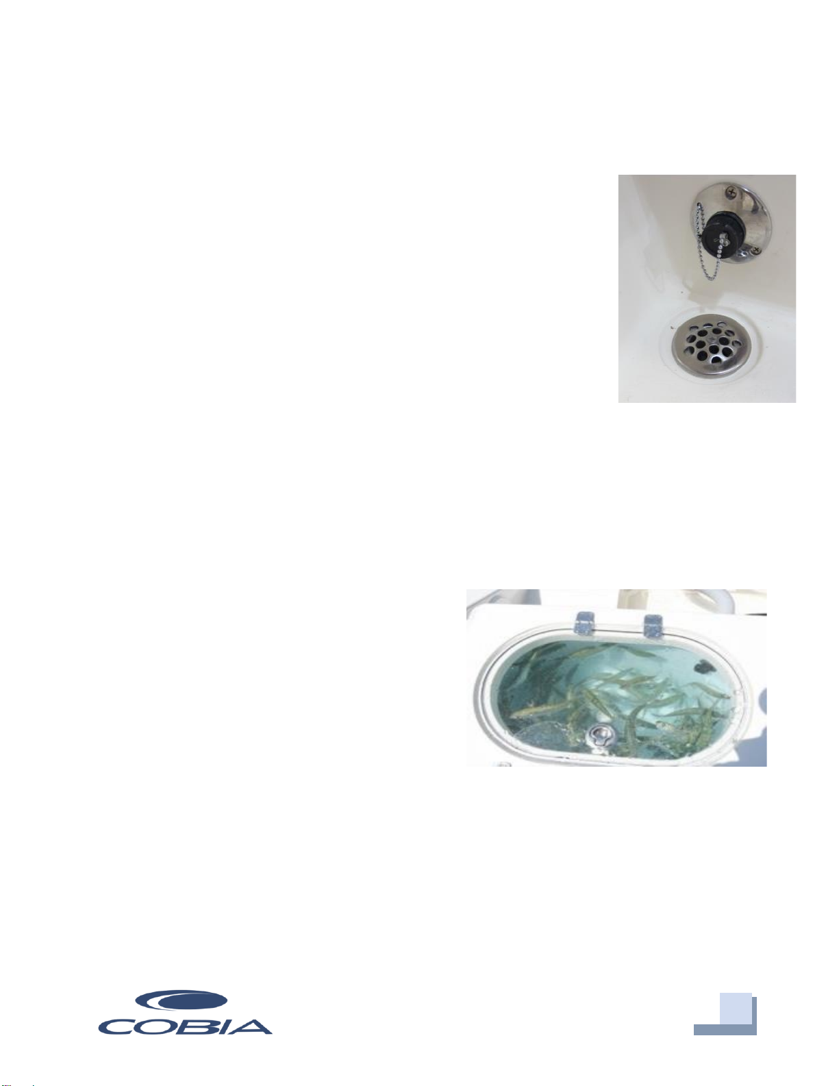
Livewell System
The livewell system is designed to keep your
baitfish alive and strong for as long as possible.
This livewell provides a cool, clean, and
oxygenated environment that allows you to keep
your baitfish alive for long periods of time. To
efficiently operate your livewell, the following
steps should be taken:
1. Open livewell hatch.
2. Install stand-up pipe snugly.
3. Ensure livewell pump ball valve is in open position.
4. Turn on livewell switch.
The livewell operates by pumping fresh seawater from the pump through an aerator
head into the livewell. Drainage is achieved through the grate on the top of the
Cockpit Drain
Livewell
19
Maverick Boat Group
3207 Industrial 29th St. • Fort Pierce, Florida 34946
(772)-465-0631 •cobiaboats.com
standpipe, which, when unobstructed, will limit the water level to the standpipe’s
highest point. A shorter standpipe can be used to keep less water in the well. This
constant drainage keeps up water flow and allows for the removal of ammonia from the
livewell, therefore extending the life of your baitfish. To drain the livewell, switch off the
pump, close pump ball valve, and remove standpipe.
Rod Storage & Fish
Lockers
Rod Storage
The 320 Center Console model comes
standard with under gunwale rod racks on
both the port and starboard sides. These give
you space to safely store an additional 6 rods
for your fishing needs.
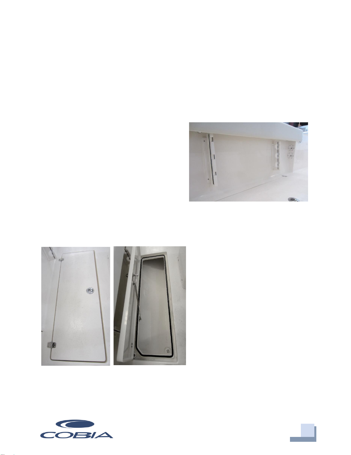
Port and Starboard Fish Lockers
The 320 CC has two fish lockers on the
port (70 gal.) and starboard (45 gal.)
sides. These lockers are insulated and
each one is connected to a macerator
with the contents being dumped
overboard. The macerators are located
in the bilge on the outboard sides of
the stringers. They can be accessed
through the bilge access hatch under
the aft folding seat. All lockers/hatches
come standard with gas shocks to
assist in opening and holding the latch
open while loading or unloading. These
lockers can also double as storage for
various other items.
Fish Locker
Port Gunwale Storage Rack

20
Maverick Boat Group
3207 Industrial 29th St. • Fort Pierce, Florida 34946
(772)-465-0631 •cobiaboats.com
Macerator Access & Operation
Macerator Switches
The switches for each fish box macerator are located on the switch panel left of the
steering helm. These can be operated independently of each other and the switches are
labeled.
Macerator Access
In order to access the macerators, open the bilge access hatch by using the controls on
the starboard side of the tackle station. Failure to remove the backrest before the
hatch is fully opened can result in damage to the backrest and/or the hatch.
The macerator pumps will be mounted in the bilge area on the inboard side of the
stringers and operate their respective fish box (port/starboard).
Starboard Macerator
Pump
Portside Macerator
Pump
Table of contents
Other COBIA Boat manuals

COBIA
COBIA 262 CC User manual

COBIA
COBIA 344 CC User manual

COBIA
COBIA 240 CC User manual

COBIA
COBIA 2016 277 CC User manual

COBIA
COBIA 2012 Cobia 237 User manual

COBIA
COBIA 237 CC 2014 User manual

COBIA
COBIA 280 DC 2019 User manual

COBIA
COBIA 2012 296 CC User manual

COBIA
COBIA 296 CC 2014 User manual

COBIA
COBIA 280 CC User manual


