Chapter 07 – Tail assembly
Chapter 08 – Installation of the servos
Chapter 09 – Assembling the modules
Chapter 10 – Gear Ratios
Chapter 11 – Installation of the ESC and Bec
Chapter 12 – Motor Belt
Chapter 01 – Serial number/Specifications
Chapter 02 –
Important notes
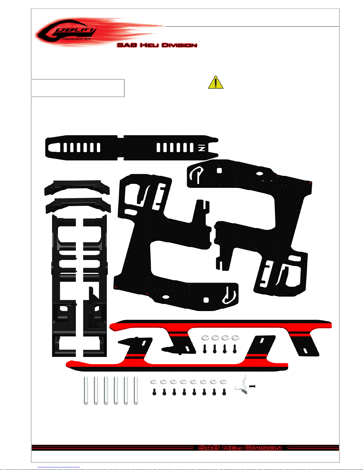
Chapter 03 – In the Box
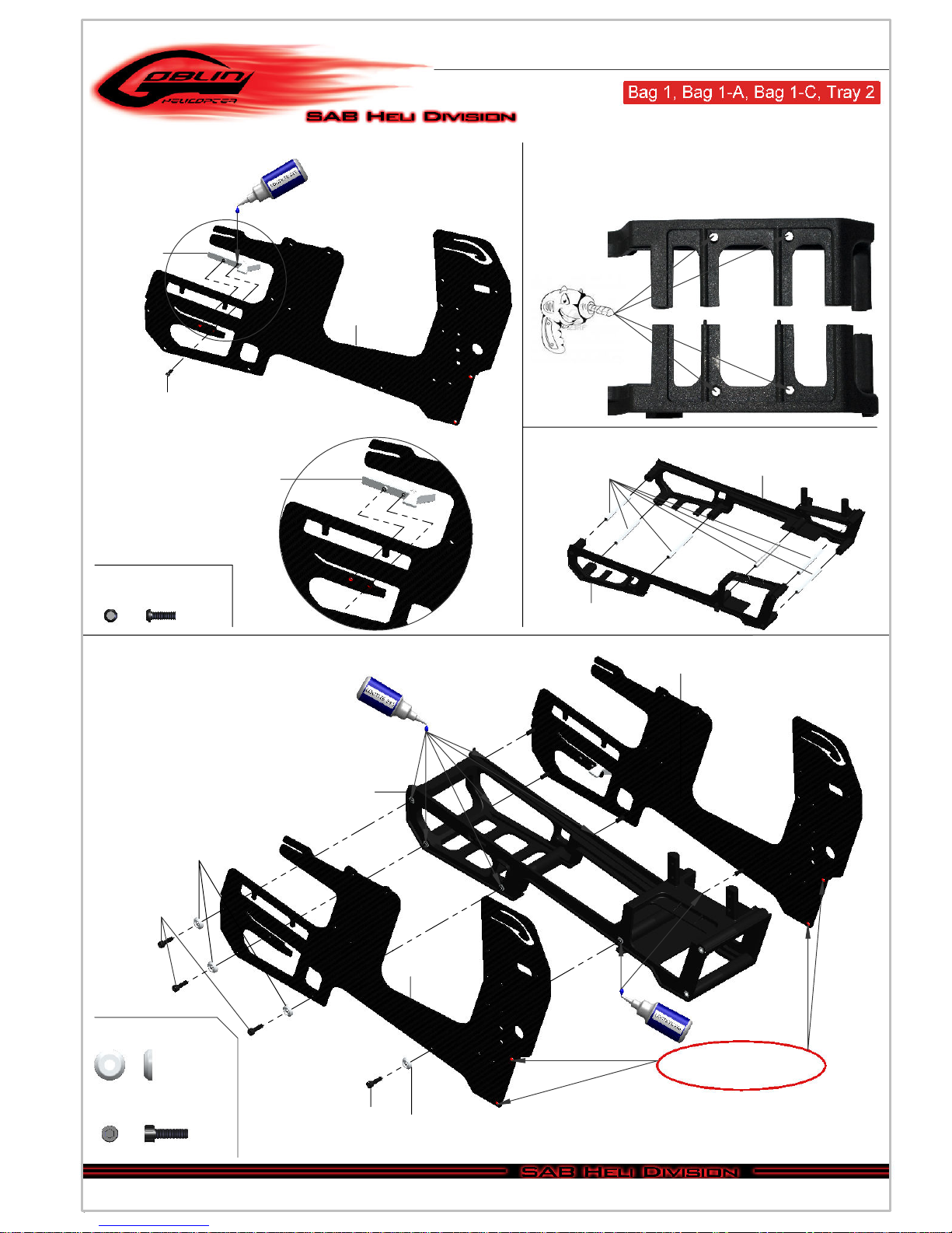
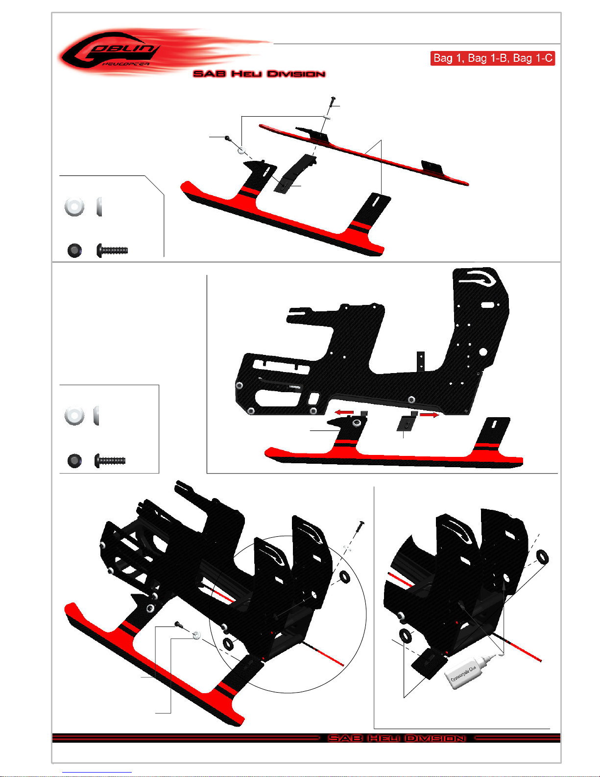
Chapter 04 – Carbon frame assembly
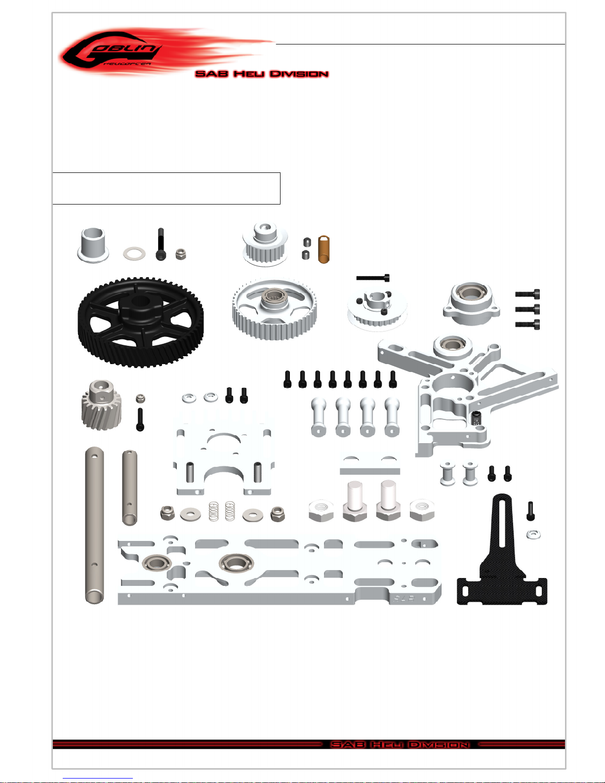
Chapter 05 – Trasmission assembly
Chapter 06 – Head assembly
INDEX
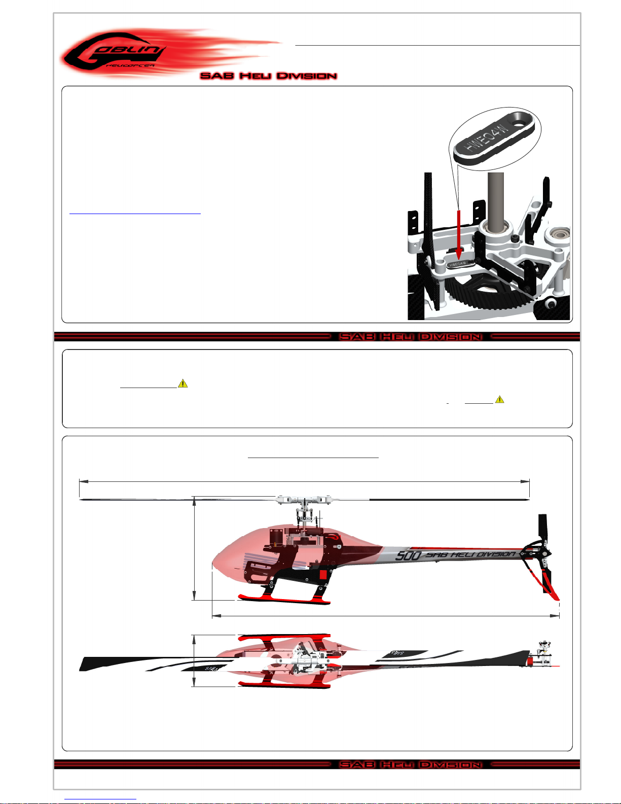
Very Impotant:
Inside Box 4, you will find Bag 9 with a red label. This bag contains your serial number
tag. Please take a moment to register your kit online via our web site at:
http://www.goblin-helicopter.com/
It is extremely important that you take a moment to register your helicopter with us.
This is the only way to ensure that you are properly informed about changes to your
kit, such as upgrades, retrofits and other important developments. SAB Heli Division
cannot be held responsible for issues arising with your model and will not provide
support unless you register your serial number.
To mount the serial number tag on your helicopter, please refer to page 26.
Thank you for your purchase, we hope you enjoy your new Goblin helicopter!
SAB Heli Division
Chapter 13 – Installation of the FBL System
Chapter 14 – Boom Assembly
Chapter 15 – Battery / Canopy
Chapter
16 –
In Flight
Chapter 17 – Maintenance
Chapter 18 – Exploded views
Chapter 19 – Spare parts
- Main rotor diameter: 1138mm (with 500mm blades)
- Main blade length: 500mm
- Tail rotor diameter: 226mm
- Tail blade length: 80mm
- Weight including standard electronics: 1900g (excluding batteries).
- Maximum motor size: diameter 52mm, height 53mm
- Battery compartment: 52x53x180mm.
SPECIFICATIONS
980mm
310mm
158mm
1138mm
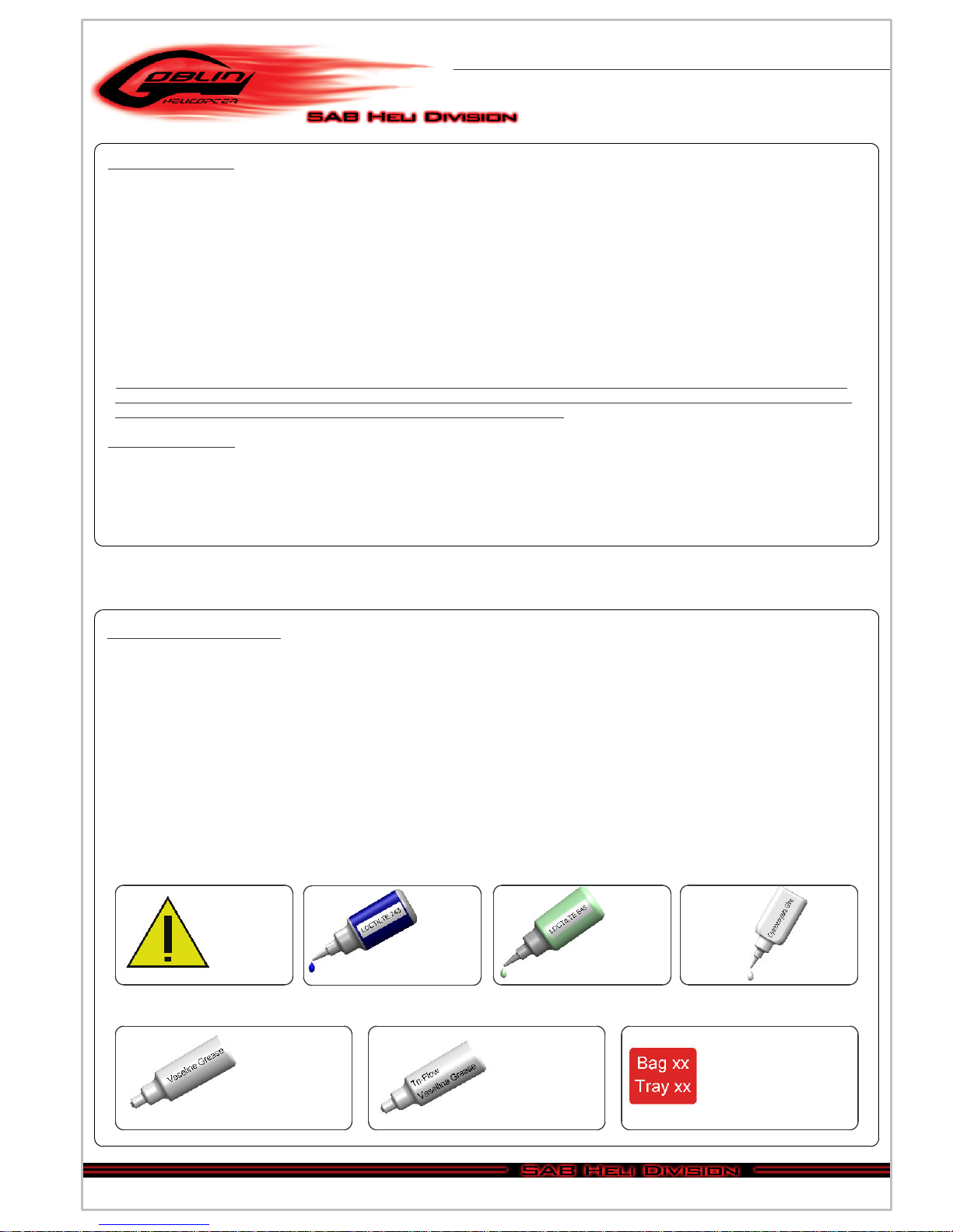
The Goblin
is a high performance radio controlled helicopter.
The design is original, moving away from traditional schemes, searching rationality for simplicity.
Our goal was to create a simple, high performance helicopter, with a minimum of mechanical components,
and simple maintenance.
Please read this user manual carefully, it contains instructions for the correct assembly of the model.
Please refer to the web site www.goblin-helicopter.com for updates and other important information.
Copyright@2013 - SAB Heli Division - All rights reserved
Page 1
Chapter 1, Serial Number