Cocoon AVS58 User manual

5.8 GHz Dual-Input Audio/Video Sender System - AVS58
www.cocoonsystems.com.au
AVS58
USER GUIDE
5.8GHzDU A l -In p U t
AU D I o / VI D E o SE n D E R Sy S t E m

5.8 GHz Dual-Input Audio/Video Sender System - AVS58
www.cocoonsystems.com.au
2
5.8GHz Dual-Input Audio/Video Sender System
CONTENTS
1. Introduction................................................................................................................... 2
2. Conformity of Use......................................................................................................... 3
3. Controls and Connections ......................................................................................... 4-5
4. Product Contents.......................................................................................................... 6
5. Connecting the Transmitter ....................................................................................... 6-9
6. Connecting the Receiver ....................................................................................... 10-11
7. Operating Instructions ................................................................................................ 12
8. Advanced Feature - Connecting to a PC or Notebook ............................................... 13
9. Troubleshooting..................................................................................................... 14-15
10. Technical Data ............................................................................................................ 16
1. In t r o d u c t I o n
The 5.8GHz Dual-Input Video Sender System (AVS58) is designed to transmit audio and
video signals without running any wires. Watch and control movies and other programs
from up to two source devices (DVD player, PayTV, VCR or other source devices) in an-
other room up to 25m away. It is also possible to use the Infra-Red (IR) remote control of
your source devices from the remote location with the IR Extender feature.
Watch a movie on any TV in your home without moving your DVD or running cables.•
Watch PayTV on any TV in your house without buying a second decoder.•
Watch downloaded movies stored on your PC on a TV in any room.•
Listen to MP3 audio from your PC on your Stereo in any room.•
Two source devices can be connected to the transmitter, you can switch between them from the•
remote location.
The AVS58 has two main components, the Transmitter and the Receiver. The Transmitter
sends an Audio/Video (AV) signal from up to two different source devices to the Receiver
via a 5.8GHz radio frequency (RF) signal - which has a range of around 25 meters and can
travel through walls and oors (range can vary depending on local conditions). The Re-
ceiver then converts the RF signal from the Transmitter back into an AV signal and outputs
this to a 2nd TV.
The AVS58 also provides the ability for you to use the remote control of your source device
(DVD, PayTV box etc.) from the 2nd room. Simply point the remote control at the Receiver
and it will convert the infrared (IR) signals of the remote control into a 433MHz radio fre-
quency signal for transmission back to the Transmitter. The Transmitter will then convert it
back to an IR signal and send it out on the IR emitter lead provided. The IR emitter lead
outputs the IR signals on its three stick-on IR emitters, one of which will need to be stuck
onto the IR receiving section on the front display of your source device.

3
5.8 GHz Dual-Input Audio/Video Sender System - AVS58
www.cocoonsystems.com.au
2. co n f o r m I t y o f us e
For carefree and safe use of this product, please read this manual and safety informa-
tion carefully and follow the instructions. The unit is registered as a device that does not
cause or suffer from radio-frequency interference. It is Australian approved and it conforms
with the Low Voltage Directory. The safety and installation instructions must be observed.
Technical manipulation of the product or any changes to the product are forbidden, due to
safety, security and approval issues.
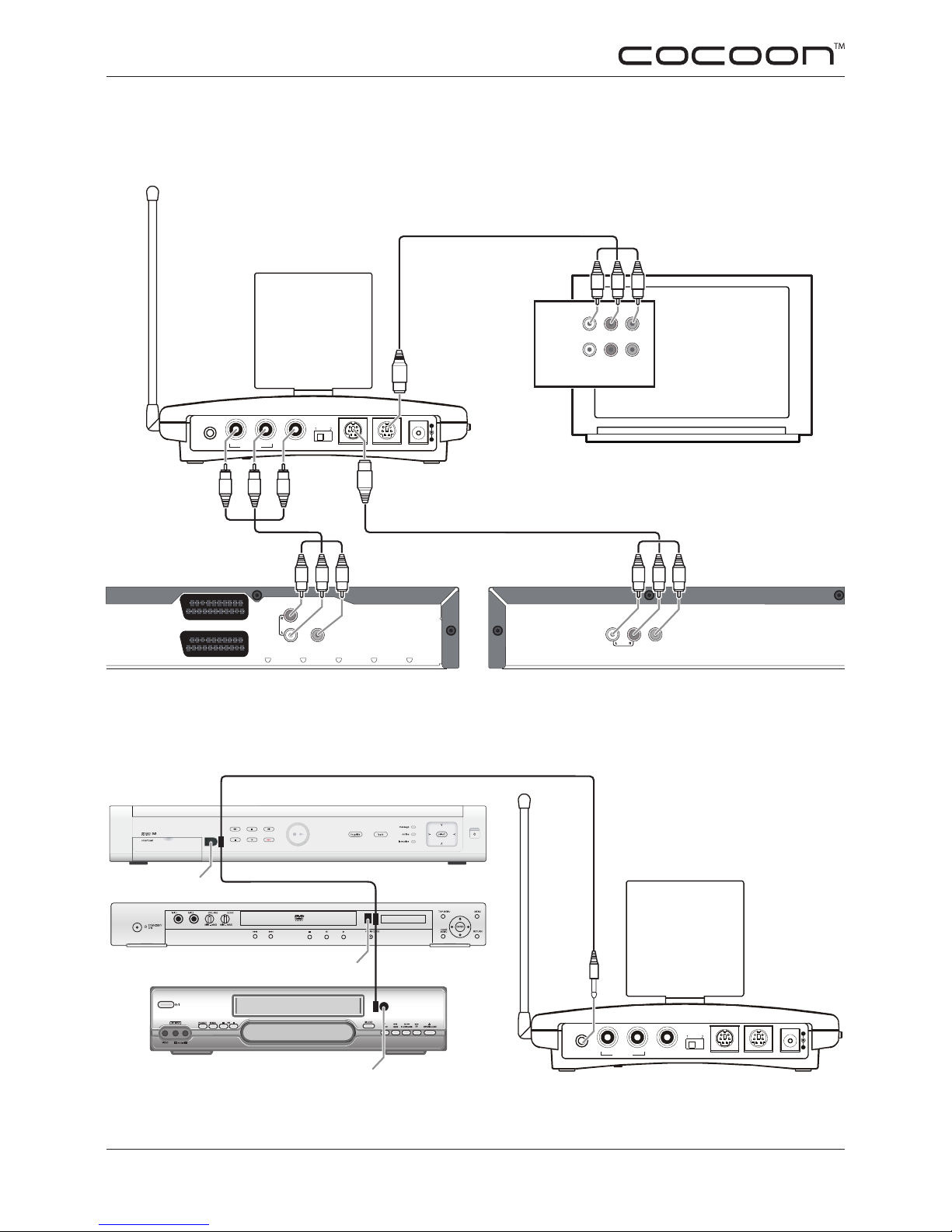
Please take care to set up the device correctly - consult this user guide.
Young children should use the device only under adult supervision. No guarantee or liability
will be accepted for any damage caused due to incorrect use of the equipment supplied,
other than indicated in this owner’s manual.
2.1 SA f E t y WA R n I n G S
To prevent short circuits, this product should only be used inside and only in dry spaces.•
Do not expose the components to rain or humidity.
Only connect the adapter to the mains after checking whether the mains voltage is the same•
as the values on the rating labels. Never connect an adapter or power cord when it is dam-
aged. In that case, contact your supplier. If there is any danger of a thunderstorm, it is a good
precaution to unplug the power supply from the mains network in order to protect it from light-
ning. The same applies if the system is to be out of use for any length of time.
Avoid strong mechanical wear and tear, extreme ambient temperatures, strong vibrations and•
atmospheric humidity.
Do not disassemble any part of the product: the device contains live parts and no user-service-•
ablepartsareinside.Theproductshouldonlyberepairedorservicedbyqualiedandauthor-
ised service personnel. Defected pieces must be replaced by original (spare) parts.
Adapters: Only connect the adapters to the mains after you have checked whether the mains•
voltage corresponds with the value on the type tags. Never connect an adapter or cable when
it is damaged. In that case, contact your supplier.
Batteries: keep batteries out of the reach of children. Dispose of batteries as chemical waste.•
Never use old and new batteries or different types of batteries together. Remove the batteries
when you are not using the system for a longer period of time. When inserting batteries be
sure the polarity is respected. Make sure that the batteries are not short circuited and are not
disposedinre(dangerofexplosion)-Note:Batteriesarenotrequiredforthisdevice.
In case of improper usage or if you have opened, altered and repaired the product yourself,
all guarantees expire. The supplier does not accept responsibility in the case of improper
usage of the product or when the product is used for purposes other than specied. The
supplier does not accept responsibility for additional damage other than covered by the
legal product responsibility.

5.8 GHz Dual-Input Audio/Video Sender System - AVS58
www.cocoonsystems.com.au
4
3. co n t r o l s a n d co n n e c t I o n s - tr a n s m I t t e r un I t
5.8 GHz
Antenna
RF Antenna
(for use with the IR
Extender feature)
A/V Out Source
Selector Switch
A/V In
(Source 1)
A/V Out
IR Extender
Jack
Power Supply
Jack
A/V In
(Source 2)
5.8 GHz Channel
Switch
ON-OFF
Switch

5
5.8 GHz Dual-Input Audio/Video Sender System - AVS58
www.cocoonsystems.com.au
TO TV
3. co n t r o l s a n d co n n e c t I o n s - re c e I v e r un I t
5.8 GHz
Antenna
RF Antenna
(for use with the IR
Extender feature)
ON-OFF
Switch
5.8 GHz Channel
Switch
Power Supply
Jack
RF Connection
(TV Out)
A/V Out Source 1 or 2
Selector Button

5.8 GHz Dual-Input Audio/Video Sender System - AVS58
www.cocoonsystems.com.au
6
4. Pr o d u c t co n t e n t s
Check that you have received the following parts:
1 x Transmitter
1 x Receiver
1 x Mains power adapter for the Transmitter, 7.2VDC 320mA
1 x Mains power adapter for the Receiver, 7.2VDC 250mA
2 x SCART to RCA adapter labelled ‘Transmitter’
1 x SCART to RCA adapter labelled ‘Receiver’
1 x RCA to RCA cable (AV cable) labelled ‘Source 1 / AV IN 1’
1 x Mini DIN to RCA cable (AV cable) labelled ‘Source 2 / AV IN 2’
1 x Mini DIN to RCA cable (AV cable) labelled ‘AV Extender’
1 x Mini DIN to RCA cable (AV cable) labelled ‘TV / AV OUT’
1 x Audio adapter 3.5mm stereo jack to RCA socket
1 x IR Extender lead, with 3 stick-on IR emitting diodes
1 x Instruction Manual
5. co n n e c t I n g t h e tr a n s m I t t e r
The transmitter is connected to an audio/video source, such as a PayTV decoder, DVD,
VCR, satellite receiver, television or even a computer’s audio/video output (see page 13).
Up to two source devices can be connected to the Transmitter, the rst (source 1) is con-
nected to the “AUDIO IN - VIDEO IN” terminal marked on the back of the Transmitter and
an optional second source device (source 2) is connected to the A/V IN terminal.
5.1 Co n n E C t I n G V I A RCA Co n n E C t I o n (y E l l o W , R E D &W H I t E p l U G S )
If your source device has RCA AV outputs available (yellow/red/white or yellow/white sock-
ets) then these can be used for connection to the Transmitter. Connect one of the supplied
AV cables to a spare input on the Transmitter (labelled AUDIO IN - VIDEO IN or A/V IN).
Next, plug the other end of the AV cable into your source device’s RCA AV outputs. The
yellow RCA plug is for video, the white and red plugs are for left and right channel audio
respectively. If your source device only has a yellow and white RCA output then do not
connect the red plug. If you don’t have a spare RCA AV outputs on your source device
because it is connected to the local TV, you may remove this connection as the Transmitter
has an output for connection to the local TV (see 5.4 on opposite page).
Important: The AV IN terminals on the Transmitter should only be connected to an AV
Output on your source device, it will not work if connected to an AV Input.
If you want to transmit audio only, connect only the white and red plugs of the AV cable.

7
5.8 GHz Dual-Input Audio/Video Sender System - AVS58
www.cocoonsystems.com.au
5.2 Co n n E C t I n G V I A SCARt Co n n E C t I o n (A D A p t E R l A b E l E D “t R A n S m I t t E R ”)
If your source device has a SCART output then this can be used for connection to the
Transmitter. Connect one of the supplied AV cables to a spare input on the Transmitter
(labelled AUDIO IN - VIDEO IN or AV IN). Next, plug the red/white/yellow plugs from the
other end of the AV cable into one of the supplied SCART adaptors labelled “Transmitter”.
Next, connect the SCART adaptor into the SCART output of your source device. If you
don’t have a spare SCART output on your source device because it is connected to the
local TV, you may remove this connection as the Transmitter has an output for connection
to the local TV (see 5.4 below).
Important: The AV IN terminals on the Transmitter should only be connected to an AV
Output on your source device, it will not work if connected to an AV Input.
If you want to transmit audio only, connect only the white and red plugs of the AV cable to
the SCART adaptor.
5.3 Co n n E C t I n G t o A3.5m m AU D I o JA C k (H E A D p H o n E S o C k E t )
You can connect the Transmitter to a 3.5mm audio jack (headphone socket) of a source
device to transmit audio only (eg. to transmit audio from a stereo or personal music player).
To do so, rst connect one of the supplied AV cables to an input on the Transmitter (labelled
AUDIO IN - VIDEO IN or AV IN), then plug just the white and red plugs into the audio adap-
tor. Next connect the audio adaptor to the 3.5mm audio output jack of your source device.
5.4 Co n n E C t I n G t H E tR A n S m I t t E R t o t H E lo C A l tV
In order to view signals from your source device(s) on the local TV (where the Transmitter is
situated), plug a supplied AV cable into this connection and plug the red/white/yellow plugs
from the other end into an AV Input on your TV. You can use the Source Selector Switch
on the rear of the Transmitter to choose which signal (Source 1 or Source 2) is transmitted
to the TV connected to the A/V OUT output (see page 9 - Fig. 5.8.2).
5.5 In f R A R E D Ex t E n D E R (f o R R E m o t E C o n t R o l o f S o U R C E D E V I C E S f R o m R E m o t E R o o m )
To enable remote control of the source device(s) from the remote location (where you will
have the Receiver installed), you have to connect the IR Extender lead. The Transmitter
outputs the IR signal (sent from the Receiver) through the 3 stick-on IR emitter diodes
positioned on the IR Extender lead. The emitters output the IR signal directly onto the IR
receiving sensor of your source device(s) (see page 9 - Fig. 5.8.3).
Connect the 3.5mm plug of the IR Extender to the IR EXT. socket on the Transmitter. Next,
stick one of the IR emitters next to the IR receiver sensor window of the device you want to
control. Information on where the IR sensor window is located should be in the manual of
your device. Further tips are provided in the troubleshooting section (pages 14-15).

5.8 GHz Dual-Input Audio/Video Sender System - AVS58
www.cocoonsystems.com.au
8
5.6 Co n t R o l l I n G mo R E tH A n on E DE V I C E
As the IR Extender lead has three IR emitters, you can simultaneously operate more than
one device from the remote location. For example, you can control the PayTV box as well
as the DVD player from the remote room.
Simply stick on an IR transmitter diode (as per the instructions in 5.5) to each device that
you want to be able to control from the remote location (see opposite page - Fig. 5.8.3).
5.7 Co n n E C t I n G t H E mA I n S po W E R AD A p t E R
Connect the mains adapter for the Transmitter to the 7.2V socket (labelled DC 7.2V).
Plug the adapter into a wall socket (2V0V a.c. ~ 50Hz).
Set the ON/OFF switch to the ON position. The operating LED will illuminate.
Raise the Transmitter aerial and direct it towards the location of the Receiver.
5.8 Ex A m p l E S o f ty p I C A l Co n n E C t I o n Co n f I G U R A t I o n S - tR A n S m I t t E R
Fig. 5.8.1 This is an example of a typical setup connecting the AVS58 to only one source - PayTV via
SCART connection as well as PayTV being connected directly to the TV. Note: Other setup congura-
tions are possible - this setup is one of the simplest and does not connect the AVS58 to the main TV.
YR W
AUDIO / VIDEO IN
INPUT 1
INPUT 2
LRV
LRV
VIDEO INAUDIO IN
RIGHT LEFT
A/V IN A/V OUT DC 7.2V
SOURCE
IR EXT.
240V 50Hz
LNB IN
RS-232-C
Y
RW
YWR
Tr ansmitter
W = White (Audio - Left)
R = Red (Audio - Right)
Y = Yellow (Video)
Note: This cable is not supplied. Connection
from PayTV box directly to TV set is respon-
sibilty of the PayTV provider.
Main TV

9
5.8 GHz Dual-Input Audio/Video Sender System - AVS58
www.cocoonsystems.com.au
VIDEO OUT
AUDIO OUT
VCR SCART
TV SCART
YR W
VIDEO OUT
AUDIO OUT
Y
R
YWR
AUDIO / VIDEO IN
INPUT 1
INPUT 2
LRV
LRV
YWR
VIDEO INAUDIO IN
RIGHT LEFT
A/V IN A/V OUT DC 7.2V
SOURCE
IR EXT.
W
W = White (Audio - Left)
R = Red (Audio - Right)
Y = Yellow (Video)
PayTV (Source 1) DVD (Source 2)
Main TV
Fig. 5.8.2 This is an example of a typical setup connecting the AVS58 to PayTV and a DVD player via
RCA connections. Note: Other setup congurations are possible - this setup also connects the AVS58
to the main TV allowing you to switch between Source 1 (PayTV) and Source 2 (DVD).
Fig. 5.8.3 This is an example of a typical setup of the IR Extender lead which allows you to use a
remote control to control your devices from the receiving location. You can control from one to three
devices - this example shows a setup allowing you to control three devices.
FOR TROUBLE SHOOTING TIPS SEE PAGES 14-15
FOR MORE WIRING EXAMPLES & HELP - PLEASE VISIT WWW.COCOONSYSTEMS.COM.AU
VIDEO INAUDIO IN
RIGHT LEFT
A/V IN A/V OUT DC 7.2V
SOURCE
IR EXT.
VCR
IR REMOTE WINDOW
IR REMOTE WINDOW
IR REMOTE WINDOW

5.8 GHz Dual-Input Audio/Video Sender System - AVS58
www.cocoonsystems.com.au
10
6. co n n e c t I n g t h e re c e I v e r
The Receiver is connected to a TV or other AV device in the remote location, which is the
room that you want to be able to view or listen to your source device(s). The Receiver picks
up the 5.8GHz signal sent from the Transmitter and outputs this signal via the A/V OUT
or TO TV (RF connection for older TVs without RCA or SCART inputs), which is then con-
nected to the remote TV.
There are several ways to connect the Receiver to your remote TV or other AV device.
6.1 Co n n E C t I n G V I A RCA Co n n E C t I o n
If your receiving device has RCA AV inputs (yellow/red/white or yellow/white sockets) then
these can be used for connection to the Receiver. Connect one of the supplied AV cables
to the A/V OUT output marked on the Receiver. Next, connect the other end of the AV cable
to a set of RCA input sockets on the receiving device (e.g. the remote TV).
The AV inputs on the remote TV are normally labelled (eg. AV1 IN, AV2 IN etc). Note down
the label of your AV input and consult the operating manual of your remote TV to determine
how to set it to display this particular input on the screen. This is often achieved by press-
ing an ‘AV button’ on the remote control, but your TV may have its own procedure which
will be explained in the manual.
Important: The A/V OUT terminal on the Receiver should only be connected to an AV Input
on your remote TV, it will not work if connected to an AV Output.
6.2 Co n n E C t I n G V I A SCARt Co n n E C t I o n
If your remote TV has a SCART input (rectangular connection labelled SCART) then this
can be used for connecting the Receiver. Connect one of the supplied AV cables to A/V
OUT output on the Receiver. Next, plug the red/white/yellow plugs from the other end
of the AV cable into the supplied SCART adaptor labelled “Receiver”. Next, connect the
SCART adaptor into the SCART input of your remote TV.
Important: The AV OUT terminal on the Receiver should only be connected to an AV Input
on your remote TV, it will not work if connected to an AV Output.
6.3 DA I S y CH A I n t H E RE C E I V E R t o An o t H E R AV DE V I C E
Instead of connecting the receiver directly to the television, you can also “daisy chain” it
with a different audio/video device (one that has AV inputs). This may be necessary if the
inputs of your remote TV are already being used by possibly a DVD, VCR etc. If this device
has a set of A/V inputs you can connect the Receiver to those, using the same instructions
above. You will then need to consult the operating manual of the AV device in order to de-
termine how to set it to display the input you have connected the Receiver to.

11
5.8 GHz Dual-Input Audio/Video Sender System - AVS58
www.cocoonsystems.com.au
6.4 Co n n E C t I n G VI A Rf (A E R I A l ) Co n n E C t I o n
Optional: If your receiving TV does not have RCA (AV) inputs (older TVs), then instead of
the RCA cable you may use an RF (aerial) cable (not included). Connect this cable be-
tween the TV-OUT port of the Receiver and the RF (antenna) input of the TV. With this op-
tion the output from the receiver is modulated to a UHF TV channel. To view the Receiver
signal with this option, you will need to tune the TV to a UHF channel - please consult your
TV’s manual for instructions.
6.5 Co n n E C t I n G t H E mA I n S AD A p t E R
Connect the mains adapter for the Receiver to the 7.2V socket (labelled DC 7.2V).
Plug the adapter into a wall socket (2V0V a.c. ~ 50Hz).
Set the ON/OFF switch to the ON position. The operating LED will illuminate.
Raise the Receiver aerial and direct it towards the location of the Transmitter.
6.6 Ex A m p l E S o f ty p I C A l Co n n E C t I o n Co n f I G U R A t I o n S - RE C E I V E R
Fig. 6.6.1 This is an example of a typical setup connecting the AVS58 Receiver to the receiving TV
via RCA connections (recommended). The diagram also shows how to connect the Receiver via RF
connection for older TVs without RCA inputs.
AUDIO / VIDEO IN
INPUT 1
INPUT 2
L R V
L R V
YW R
A/V OUT DC 7.2V
1 2
TO TV
RF IN
FOR TROUBLE SHOOTING TIPS SEE PAGES 14-15
FOR MORE WIRING EXAMPLES & HELP - PLEASE VISIT WWW.COCOONSYSTEMS.COM.AU
W = White (Audio - Left)
R = Red (Audio - Right)
Y = Yellow (Video)
Optional: This is a standard RF connec-
tion for older TVs without RCA AV inputs
(cable not included)

5.8 GHz Dual-Input Audio/Video Sender System - AVS58
www.cocoonsystems.com.au
12
7. oP e r a t I n g In s t r u c t I o n s
Please check the Product Contents section to make sure you have all of the•
parts listed (see page 6).
Review and familiarise yourself with your AVS58 Audio / Video Sender Sys-•
tem connections (see pages 4-5).
Please read and follow the instructions for connecting the Transmitter to your•
main TV (see pages 6-9).
Please read and follow the instructions for connecting the Receiver to your•
receiving TV (see pages 10-11).
7.1 tR A n S m I t t E R / RE C E I V E R po S I t I o n I n G
Open up the Transmitter and Receiver aerials and point them toward each•
other in an imaginary straight line. You may need to experiment with the po-
sition of both aerials until you obtain the optimal sound/image.
Position the Receiver so that the front (where the power LED is located) is•
facing you - this is important for the operation of the IR Extender feature.
7.2 SE t t I n G tR A n S m I t t E R / RE C E I V E R CH A n n E l S
Your AVS58 system has four channels – i.e., four different frequencies for transmitting the
AV signals. The channel switch is on the bottom of both devices (see pages 4-5).
The Transmitter and Receiver need to be set to the same channel.•
Test which channel (A, B, C or D) provides the best reception.•
7.3 SW I t C H I n G bE t W E E n So U R C E S (D E V I C E S )
If you have connected two source devices to the Transmitter (see pages 6-9), you can
now use the SOURCE 1 / 2 switch on the back of the Receiver to switch between the rst
(Source 1) and the second (Source2) devices. To do this, hold the SOURCE 1 / 2 button
down on the back of the Receiver until it switches sources (approx. 5 sec).
You can also point a remote control at the front of the Receiver and press and hold any
button until the source changes (approx. 5 sec).
7.4 US I n G t H E IR (R E m o t E ) Ex t E n D E R fE A t U R E
If you have connected the IR Extender lead correctly (see pages 7-9), you can use a re-
mote to control your source device(s). Simply point your remote at the Receiver and use
as normal (light will “blink” conrming receipt of command). You can also use your remote
to switch between Source Channels (see 7.3 above).

13
5.8 GHz Dual-Input Audio/Video Sender System - AVS58
www.cocoonsystems.com.au
8. ad v a n c e d fe a t u r e - co n n e c t I n g t o aPc o r no t e b o o k
You can also connect the Transmitter to a computer in order to transmit video and/or audio
from your PC. Usually it doesn’t make sense to transmit computer output to a TV for run-
ning computer applications, as the TV’s screen display is not usually good enough to dis-
play the higher resolution computer image (unless you have a plasma or LCD TV - check
manual for more information). However, if you want to watch videos or listen to audio saved
on your PC, displaying them via the TV or listening to audio on a stereo is a nice feature.
The requirement to be fullled is that the computer must have a video output that provides
video images suitable for a TV (see your graphic card’s manual) and the operating system
and the drivers for your graphics card must support composite video output.
8.1 SE t U p GU I D E
Output via video output is activated differently depending on your operating system and
graphics card. As there are numerous combinations of these, only general instructions are
provided here. Check the operating instructions for your computer and/or graphics card to
see how you can divert the image to video output.
Close all programs and switch off your computer.•
Refer to the operating instructions for your PC and follow the instructions for using video•
output.
Connect the yellow plug on the AV RCA cable to the graphics card’s video output. If your•
graphics card does not have a RCA output, use a suitable adapter (optional accessory)
Connect the red and white plugs on the Mini DIN AV RCA cable to the appropriate audio output•
on your PC. PCs usually have 3.5mm stereo jacks, so you can use the adapter supplied.
Connect the cable’s mini DIN plug to a spare input on the Transmitter (AV IN 1 or AV IN 2).•
Now switch on the Transmitter, the Receiver and the TV, and choose the appropriate AV input•
on your TV.
Start the PC and wait until the operating system has fully loaded.•
Go to Properties and continue with Display Properties for the respective operating software.•
Change settings according your display device or graphics card to enable the video output.•
Check the relevant operating instructions to see how you should proceed. If all the settings
are correct, the images from the PC will now be displayed on the TV.
NOTE: The differences between operating systems and graphics cards mean that we can-
not guarantee the functionality described in this section, and can’t give further technical
support on PC issues. If you do not get a picture then rst connect the graphics card output
directly to the TV to ensure that the PC is actually outputting a compatible signal. Please
visit cocoonsystems.com.au for more information.

5.8 GHz Dual-Input Audio/Video Sender System - AVS58
www.cocoonsystems.com.au
14
9. tr o u b l e s h o o t I n g
The AVS58 Audio / Video Sender System you have purchased is built in accordance with
state-of-the-art technology and is safe for operation when used in accordance with the
instructions. However, problems or malfunctions may still occur. The following list denes
possible problems and associated solutions:
9.1 nopI C t U R E o R So U n D
Is the source device(s) (PayTV decoder, DVD Player, etc.) switched on?•
Are the Transmitter and Receiver both supplied with power and switched on (power lights•
should be illuminated)?
Is the source device(s) connected correctly to the Transmitter (see pages 6-9)?•
Is the remote TV connected correctly to the Receiver (see pages 10-11)?•
Areallcablespluggedinrmly?•
Are the source device(s) congured to the correct outputs (the ones the Transmitter is•
connected to – you may need to consult your device manuals)?
Have the Transmitter and Receiver been inadvertently switched? (The Transmitter should be•
connected to the source device(s) and the Receiver in the remote location).
Is your Receiving TV (in the remote location) set to the correct input channel that the Receiver•
is connected to (e.g AV 1 - you may need to consult your TV manual)?
9.2 noSo U n D RE p R o D U C t I o n
Is the volume turned up on your source device(s) and receiving TV?•
Isthesourcedevice(s)conguredtooutputsoundontheoutputsconnectedtotheTransmitter•
(you may need to consult your device manuals)?
AretheplugsoftheAVcablesrmlypluggedintheconnectingsocketsofthesourcedevice(s),•
Receiving TV, Transmitter and Receiver?
Are the RCA plugs (Yellow = Video, Red = Right Audio, White = Left Audio) or SCART adapter•
of the AV cables connected to the correct sockets (see pages 6-11).
9.3 In t E R f E R E n C E /DI S t o R t I o n W I t H So U n D A n D /o R pI C t U R E
The range between the Transmitter and Receiver may have been exceeded (if there are solid•
brick or a number of walls between the Transmitter and Receiver this will reduce the range of
the system).
Is there a metallic barrier (e.g. steel reinforced concrete wall) between Transmitter and•
Receiver? If so, try relocating the positions of the Transmitter and/or Receiver.

15
5.8 GHz Dual-Input Audio/Video Sender System - AVS58
www.cocoonsystems.com.au
9.3 In t E R f E R E n C E /DI S t o R t I o n W I t H So U n D A n D /o R pI C t U R E (Co n t .)
Are the antennas and of the Transmitter and Receiver raised and pointed towards each other?•
Try moving the position of the antennas to improve the signal (see page 12).
Is a strong source of interference, e.g. 5.8GHz cordless phone, analectic motor, radio set,•
microwave over etc. close by? If so, turn off these devices to investigate whether they are
causingtheinterference.Ifyoundadeviceisinterfering,trymovingoffendingequipmentto
a different location.
Are the Transmitter and Receiver too close together (less than 2 meters)? This may lead to•
overdriving the Receiver. If so, try increasing the distance between them or change the
position of the antennas.
Have the channel select switches of the Transmitter and the Receiver been set to the same•
channel? If not make sure they are set to the same letter (A, B, C or D) – (see page 12).
IfyouareusingtheRFoutoftheReceiver,ensurethattheconnectedTVisne-tunedtothe•
correct UHF channel (you may need to consult your TV manual – see page 11).
9.4 tH E RE m o t E Co n t R o l Do E S no t Wo R k f R o m t H E RE m o t E lo C A t I o n
Has the IR emitter lead been plugged into the Transmitter correctly and one of the IR emitters•
adhered next to the IR remote window of the source device(s) that you are trying to control
(see page 9 – Fig. 5.8.3)?
Is the IR emitter adhered in the correct location on the source device(s)? If the location•
of the IR remote window is not obvious, a good way to ensure the correct location is to have
someone constantly attempt to change channels by using the remote control in the remote
location. At the same time you can slowly move one of the IR emitters along the front of
thesourcedeviceuntilyoundthelocationwhereitstartsresponding.ThenadheretheIR
emitter to that position.
fu r t h e r te c h n I c a l su P P o r t
If you have tried everything in this troubleshooting section but are still having problems with
your audio/video sender, further support information is available on our web site.
www.cocoonsystems.com.au

5.8 GHz Dual-Input Audio/Video Sender System - AVS58
www.cocoonsystems.com.au
10. te c h n I c a l da t a
Power supply Transmitter: 230V AC / 7.2VDC 320mA
Power supply Receiver: 230V AC / 7.2VDC 250mA
4 channels: Channel A : 5.758 GHz Channel B : 5.776 GHz
Channel C : 5.794 GHz Channel D : 5.812 GHz
Bandwidth: 5.8GHz Power output: 25mW
IR Extender: 433.92MHz Power output: <1mW
AV-Input: 1x Mini DIN input 1x 3 RCA Plug (2 Audio 1 Video))
AV-Output: 1x Mini DIN
Video Input/Output: 1 Vpp (type) / 75 Ohms
Audio Input/Output: 1 Vpp (type) / 600 Ohms
Dimensions: Transmitter: 155x102x30 mm Receiver: 115x102x30mm
Weight: Transmitter: 178g Receiver: 172g
Cocoon™ 5.8GHz Audio / Video Sender System
AVS58 Transmitter and Receiver
N16277
DID yoU knoW yoU CAn ADD ExtRA RECEIVERS to ExpAnD yoUR SyStEm?
= + +
You can now transmit the signals from your Cocoon™ AVS58 5.8 GHz Audio / Video Send-
er System to more than one TV throughout your home! Extra receivers are now available.
Visit www.cocoonsystems.com.au for more information.
C o C o o n ™ I S p R o U D l y D I S t R I b U t E D b y G E n E R A l W H o l E S A l E p t y . l t D .
Table of contents
Other Cocoon Media Player manuals