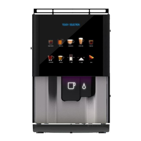
COFFEtek VITRO S2 Series User manual

VITRO S2/3 RANGE
TECHNICAL MANUAL
81038540
Revision 1

VITRO S2/3
Revision 1
28/02/2017
2
VITRO S2/3 BEVERAGE MACHINE
TECHNICAL MANUAL
FOREWORD ..................................................................................................................................4
SECTION 1 TECHNICAL INFORMATION......................................................................................6
INTRODUCTION ................................................................................................................................................6
SERVICES REQUIRED......................................................................................................................................8
Electrical Supply.............................................................................................................................................8
Water Supply..................................................................................................................................................8
GENERAL DESCRIPTION.................................................................................................................................9
Cabinet Front..................................................................................................................................................9
Cabinet Interior...............................................................................................................................................9
WATER SYSTEM.............................................................................................................................................10
Heater and Boosting.....................................................................................................................................10
Tank Filling & Overflow Protection...............................................................................................................11
ELECTRICAL AND ELECTRONIC SYSTEM..................................................................................................12
Functional Description..................................................................................................................................12
Circuit Description ........................................................................................................................................13
SECTION 2 PROGRAMMING ..................................................................................................... 14
INTRODUCTION ..............................................................................................................................................14
INTERNAL KEYPAD LAYOUT........................................................................................................................15
KEYPAD FUNCTIONS.....................................................................................................................................15
OPERATOR PROGRAM..................................................................................................................................16
ENGINEER PROGRAM ...................................................................................................................................18
Program Options ..........................................................................................................................................19
SECTION 3 INSTALLATION AND MAINTENANCE .................................................................... 44
INTRODUCTION ..............................................................................................................................................44
SAFETY WARNINGS.......................................................................................................................................45
FROST WARNING...........................................................................................................................................46
INSTALLATION ...............................................................................................................................................46
Location........................................................................................................................................................46
Levelling .......................................................................................................................................................46
Securing .......................................................................................................................................................46
CONNECTING THE WATER SERVICES........................................................................................................48
CONNECTING THE ELECTRICAL SERVICES..............................................................................................49
DESCALING THE TANK .................................................................................................................................51

3
28/02/2017
Revision 1
VITRO S2/3
COMMISSIONING............................................................................................................................................52
DAILY HYGIENE.......................................................................................................................... 54
CLEANING INSTANT UNITS...........................................................................................................................54
CLEANING THE COFFEE BREWER..............................................................................................................54
RESET COUNTERS.........................................................................................................................................56
WEEKLY HYGIENE.............................................................................................................. 57
CLEANING TEA BREWER..............................................................................................................................57
CLEANING INSTANT UNITS...........................................................................................................................57
FILLING PRODUCTS................................................................................................................... 59
FILLING BEAN HOPPER ................................................................................................................................59
FILLING PROCEDURE (INSTANT & TEA).....................................................................................................59
FAULT FINDING GUIDE.............................................................................................................. 60
SECTION 4 SCHEMATIC AND EXPLODED PARTS DIAGRAM................................................. 62

VITRO S2/3
Revision 1
28/02/2017
4
FOREWORD
1. The information contained in this technical manual is applicable to the Vitro S2/3 Beverage
Machine Range. Due to customer requirements some units may vary from the one
described in the manual.
2. Personnel who have undergone relevant equipment training must only undertake
maintenance of the beverage machine.
3. The manufacturer reserves the right to make changes, without notice, to the design of the
beverage machine, which may affect the information, contained in this manual.
4. The Vitro S2/3 Beverage Machine is designed for indoor use, in an environment with an
ambient temperature range of between 1ºC and 40ºC.
5. THIS APPLIANCE CAN BE USED BY CHILDREN AGED FROM 8 YEARS AND ABOVE
AND PERSONS WITH REDUCED PHYSICAL, SENSORY OR MENTAL CAPABILITIES
OR LACK OF EXPERIENCE AND KNOWLEDGE IF THEY HAVE BEEN GIVEN
SUPERVISION OR INSTRUCTION CONCERNING USE OF THE APPLIANCE IN A SAFE
WAY AND UNDERSTAND THE HAZARDS INVOLVED. CHILDREN SHALL NOT PLAY
WITH THE APPLIANCE. CLEANING AND USER MAINTENANCE SHALL NOT BE MADE
BY CHILDREN WITHOUT SUPERVISION.

5
28/02/2017
Revision 1
VITRO S2/3
This page is intentionally blank.

VITRO S2/3
Revision 1
28/02/2017
6
Section 1
Technical Information
INTRODUCTION
1. The Vitro S2/3 Beverage Machine dispenses hot beverages in response to a capacitive key
selection. All beverages are dispensed in cup measurements. A liquid crystal display
provides status indications and operational information. All operations are microprocessor
controlled.
2. A cup is placed under the dispense head and the selection is made via a capacitive key
selection. The drink is then dispensed in the required quantity. The machine does not
accept money, but a feature such as this can be added.
3. The status of the machine may be monitored, and the configuration altered, by accessing a
program using the keypad and display. The program offers a menu of options; each
consisting of a number of sub-options which can be altered.
4. The Vitro S2/3 Beverage Machine has a feature, which heats the water in the boiler very
quickly, with one heater connected, from a 230V~, 16A single-phase supply.
FIG 1.1 VITRO S3 BEVERAGE MACHINE
Model shown is S3 FBT

7
28/02/2017
Revision 1
VITRO S2/3

VITRO S2/3
Revision 1
28/02/2017
8
SERVICES REQUIRED
Electrical Supply
5.
(a) Single Heater Operation
Supply voltage : 230V~, 50Hz, single phase, fused supply
Current rating : 10A/16A
(b) The fused electrical supply should terminate at an appropriate isolator located within
1m of the beverage machine.
Water Supply
6.
(a) 15mm dia. Water mains supply, terminating at a convenient stop tap located within
1m of the beverage machine.
(b) Water pressure : 0.1 MPa minimum, 0.8 MPa maximum
(c) A 15mm double backcheck valve, with inspection port, should be fitted prior to the
flexible hose. The mains Water Supply should be fitted with a suitable water blocker.

9
28/02/2017
Revision 1
VITRO S2/3
GENERAL DESCRIPTION
7. The Vitro S2/3 Beverage Machine is a free-standing unit which may be mounted on a
secured table, bench, cabinet or food and drink counter.
Cabinet Front
8. The cabinet front door has a large glass panel and located within this panel are 10
capacitive touch switches. On the rear of the door is the display for accessing product
information and machine settings with an internal keypad which provides access to the
Operator’s and Engineer’s Program and a USB port
9. The panel can, when unscrewed, be hinged to give access to the ZMCU control board,
button control board, ZMCU adaptor and capacitive touch PCB’s.
Cabinet Interior
10. A swivel open door provides access to the plastic product containers, each fitted with a
gear driven worm screw located in the base of each canister to dispense ingredients in
exact amounts.
The ingredients are mixed with hot water in mixing bowls prior to the beverage being
poured from the dispense head.
A plastic agitator is located inside of the milk topping and chocolate canister to ensure free and
consistent flow of product. Additionally a whipper unit, located beneath the mixing bowls,
ensures that the product and water are correctly mixed.
The ingredient canisters must be removed for filling of the products and when all three
canisters are removed and steam hoods of the mixing bowls are removed the extract chamber
can be removed for cleaning.
11. Located on the upper left hand panel is the machine on/off switch, which controls the power
to the MPU, power supply. Access to all other components is either by removal of the lid
assembly/boiler cover and motor shelf.
12. Further access to the inner components is achieved by removing the left-hand side panel
by unscrewing the location screw and then the panel will drop down clear of its keyhole
slots. Removing this panel gives access to all internal components.
13. The mains electricity supply cable enters the machine via a cable gland on the base panel
of the machine, where it terminates in a terminal block. The supply is then connected via
the terminal block, line filter to the on/off switch on the front of the machine.

VITRO S2/3
Revision 1
28/02/2017
10
WATER SYSTEM
14. The main water supply enters the machine via an inlet valve, which is mounted in the
cabinet base panel. A length of tube then takes the water supply into the top of the water
boiler via an air break into a channel, which is directed, to the bottom of the heater tank.
15. Hot water is dispensed from the boiler, via the appropriate solenoid operated valve, to the
mixing bowl. A length of tube directs any overflow from the boiler via overtemp safety
thermostats to the waste tray.
16. The cold water mains supply enters the machine at the base of the cabinet and connects
with inlet valve, which controls the flow of water to the boiler. The water is maintained at a
constant level in response to signals from a water level probe which is connected to the
Controller Board.
17. The water is heated to the required temperature by a single element. The Controller Board
ensures that the temperature is maintained to a predetermined level by controlling the
supply to the heater in response to signals from the N.T.C. temperature sensor which forms
part of the level/temperature probe assembly.
18. Hot water from the boiler is fed directly to the mixing bowls where it mixes with the
dispensed ingredient to produce the selected beverage. Solenoid operated valves
distribute the hot water to the selected mixing bowl, the amount of water being determined
by the program setting.
19. The temperature of the water is monitored by the Controller Board via a sensor inserted into
the tank, thus causing the supply to the heater to be removed when the water in the boiler
reaches its required temperature setting. If the temperature in the boiler increases causing
the water to boil over, the water will flow over the overtemp sensors which will cut off the
electrical supply to the heating elements. This sensor is mounted on top of the heater tank
and are re-settable.
Heater and Boosting
20. The heating control system employs an intelligent algorithm to obtain maximum
performance as follows:-
Boost operation takes place when the inlet valve opens following a selection being taken. The
heater control algorithm is instructed to turn on the SSR for the duration specified in the
variable CUP BOOST
If the temperature is 3° more than the DESIRED TEMPERATURE, set in the CHANGE
SETTING MENU all boosting operations are disabled.
If the actual temperature is between 0 –1.5° less than the DESIRED TEMPERATURE the
SSR toggles ON & OFF unless a boost operation is in progress then the SSR are ON.
If the actual temperature is between 2° - & 3° less than the desired temperature the SSR is
ON. Boost operations are as above.
If the actual temperature is more than 3° below the desired temperature the SSR’s are ON.

11
28/02/2017
Revision 1
VITRO S2/3
Tank Filling & Overflow Protection
21. The control system will only open the inlet valve for a maximum of 40 seconds. If the tank
is not full at the end of this time the machine will enter a fault condition. The internal display
will read “TANK FILL FAULT CALL OPERATOR”. This fault can be cleared by switching the
machine off and on.
Note: An empty tank may take several cycles to fill completely.
22. The second protective mechanism is designed to act as a fail-safe in the event that a slow
leak occurs which does not result in the liquid entering the drip tray. The machine will
cease all attempts to fill the tank after 20 tank top ups have been made, if no selections
have been taken in the meantime.
FIG 1.2 WATER SYSTEM –FUNCTIONAL DIAGRAM
Model shown is S3 BTC
Inlet Valve
Overtemp
Cutout 1
Overflow
Valves
A
COFFEE
BREWER
A
Boiler
B
C
Mixer
HOT WATER

VITRO S2/3
Revision 1
28/02/2017
12
ELECTRICAL AND ELECTRONIC SYSTEM
Functional Description
23. The MPU Controller Board employs Microprocessor technology to monitor and control the
operation of the beverage machine. The board contains the main System Program, the
Operator’s Program and the Engineer’s Program, each stored in programmable read only
memory.
24. Variables, such as the amount of ingredients dispensed, are stored in non-volatile random
access memory (NVRAM) and are called up by addressing either the Operator’s Program
or the Engineer’s Program as appropriate.
25. The main System Program tasks the microprocessor with continually checking the status of
the input devices (keypad, probe, etc.) and responding to data received by signalling the
output devices (LCD display, motors, whippers etc.) to take the appropriate action. The
System Program also requests the microprocessor to interrogate the variable settings in
NVRAM and to modify its actions accordingly.
26. Output transistors and F.E.T. devices on the MPU Controller Board convert signals from the
Controller’s microprocessor circuit to the current drive necessary to operate output devices,
i.e. motors, whippers and inlet valve.
FIG 1.3 ELECTRICAL &
ELECTRONIC SYSTEM
–FUNCTIONAL
DIAGRAM
1.
HEATER SSR'S
VALVES
MOTORS/FAN
CONTROLLER
BOARD
WATER LEVEL
KEYPAD
TEMP SENSOR
DISPLAY
PUSHBUTTONS
Capacitive Touch
Screen Selection

13
28/02/2017
Revision 1
VITRO S2/3
Circuit Description
27. If the beverage machine is supplied by a 230V~ single-phase supply from a 10A or 16A
outlet (or from a 13A domestic outlet), only 15A fuse protects the heater circuit, a solid state
relay (SSR) contact and high temperature cut-out is placed in the circuit of heater
28. The SSR switches the supply to the heaters as directed by the MPU Controller in response
to data received from the temperature sensor part of the temperature/level probe, thus
maintaining the water in the boiler at the correct temperature. However, if the water in the
boiler starts to boil, the high temperature cut-out remove the supply to the heater. Reset
buttons for cut-out is accessible at the top of the machine.
29. A 230V~ ac main supply is taken from terminal block to the Power Supply PCB via the
on/off switch. The Power Supply PCB provides DC supplies of 24V, 12V and 5V. The 24V-
dc output supplies the ingredient motors, whipper motors, extract fan, SSR and solenoid
operated valves. The 12V-dc output supplies the MPU Controller Board and operational
coin acceptor (if fitted).
30. The MPU Controller Board continually checks the status of input devices connected to
plugs J1 and J3, and responds to any change of state by signalling the operation of the
relevant output devices via on-board current drive transistors. Thus, for example, the water
level probe controls the operation of the inlet valve and the temperature sensor controls the
operation of the SSR.
31. The dispensing of a beverage begins with the keypad selection, which is scanned by the
MPU Controller Board via a ribbon connector. Which passes through the button control
board to the MPU. Control Signals corresponding to the required actions are then
generated by the MPU Controller to operate the relevant output devices in the correct
sequence and for the specified duration. Operator data information is sent in parallel form
to the (LCD) Display.

VITRO S2/3
Revision 1
28/02/2017
14
Section 2
Programming
INTRODUCTION
1. The Vitro S2/3 Beverage Machine provides two discrete user programs: The Operator’s
program and the Engineer’s Program. The Operator’s Program is available to both the
Operator and the Service engineer, but the Engineer’s Program is only available to the
SERVICE ENGINEER.
2. Both the programs are stored in programmable read only memory on the Controller Board.
The values and settings (Variables), which the program allows the programmer to alter, are
stored in NVRAM (non-volatile random access memory).
3. Settings are maintained, without the need for back-up battery, when the power supply is
removed.

15
28/02/2017
Revision 1
VITRO S2/3
INTERNAL KEYPAD LAYOUT
KEYPAD FUNCTIONS
4. The Operator’s Program is available to the operator and Service Engineer. The Program
provides options for counting the number of drinks dispensed for each beverage, monitoring
the weight of ingredients used, showing the total vends dispensed and resetting the drink
dispensed counters if applicable. Additionally, the operator can set the machine to Out of
Service if required.
5. Keypad functions when used in the Operator’s programming mode, are as follows:-
Key (ENTER) used to access a function.
Key (PROG) used to access the operators program, then used to change menu
functions.
ARROWS UP (), DOWN (), LEFT (), RIGHT () are used for adjustments when
in program mode.
key is used for selecting option when in output test mode.
FLUSH PROG
ESC ENTER

VITRO S2/3
Revision 1
28/02/2017
16
OPERATOR PROGRAM
Accessing the Operators Mode
6. Accessing the Operator program is by pressing the PROG key on the internal keyboard.
The display will show:
PRESS DRINK TO DISPLAY COUNTER
DISPLAY COUNTER
7. The DISPLAY COUNTER option is accessed on entering the Operator’s Program. The
resettable vend counts may be viewed by pressing each drink key (as shown on the
keypad) in turn.
8. To access other options, press PROG on the internal keypad. The other options are as
follows:
Total Vends
Reset Counters
Disable Vends
Reset Grout Counter
View Ingredient Counters
Machine Serial No.
TOTAL VENDS
9. Access the Total Vends Count option using PROG key, the display will show total vend
count.
RESET COUNTERS
10. Access Reset Counters by using PROG key, to clear drink counters press ENTER. The
display will show:
ARE YOU SURE
ENTER (Y) ESC (N)
DISABLE VENDS
11. Access the DISABLE VENDS option by pressing the PROG key and then press ENTER
when DISABLE VENDS is displayed. This will then disable all of the vends selections until
they are re enabled.
VIEW INGREDIENT COUNTERS
12. Access the View Ingredient Counters option by using PROG key. Press ENTER to display

17
28/02/2017
Revision 1
VITRO S2/3
the first counter, then press the UP arrow to scroll through the others.
MACHINE SERIAL NUMBER
13. Access the MACHINE SERIAL NUMBER by pressing the PROG key until the machines
serial number is displayed on the LCD display.

VITRO S2/3
Revision 1
28/02/2017
18
ENGINEER PROGRAM
Accessing the Engineer Program
14. The operator program must be accessed before the Engineer Program can be accessed,
the operation is as follows:
Press PROG to access the Operator Program, the display will show:
PRESS DRINK TO DISPLAY COUNTER
Press PROG again, the display will show:
TOTAL VENDS
Now, press the “Star” key on the internal keypad. The display will now show:
SELECT DRINK TO MODIFY

19
28/02/2017
Revision 1
VITRO S2/3
Program Options
15. Programming options are available as follows:
SELECT DRINK TO MODIFY
SELECT DRINK TO TEST
MOVE OR COPY DRINK
INPUT TEST
OUTPUT TEST
CHANGE ACCESS CODE
CHANGE PRICE OR INHIBIT DRINK
SET INGREDIENT THROW RATE
EVENT LOG
BLUETOOTH MENU
USB ACTIVITIES
SET MACHINE SERIAL No
(Inhibited by default only appears when enabled)
I2C STATUS
SET DATE AND TIME
TIMED EVENTS
TANK STATUS
CHANGE SETTINGS
PRESS DRINK FOR FIXED COUNTERS
EDIT BIN NAMES
SET FACTORY DEFAULTS
LEAVE ENGINEER PROGRAM
16. Repeated pressing of PROG key causes the program to scroll through the options in the
above sequence. Therefore a specific option is accessed by pressing PROG key until that
option is displayed. To access any program press ENTER.

VITRO S2/3
Revision 1
28/02/2017
20
SELECT DRINK TO MODIFY -INGREDIENT/WATER/WHIPPER ADJUSTMENTS PROGRAM
17. The Vitro S2/3 program provides total flexibility in setting the function of the selection
buttons. Each button has the possibility to add to its recipe any of the ingredients in the
machine. Thus, for example, the button programmed to dispense chocolate will have in its
control variables list, parameters to control the coffee, topping and decaf/espresso motors,
mixers and valves. It would in theory be possible to program a button to have a little of each
product available. The program is arranged in sections showing the start time and running
duration for the ingredient motors, dispense valves and mixer motors. There is a start time
and running duration for each actuator. The times are in tenths of a second. In addition to
this other selection, specific parameters are included in the list of settings that can be
changed.
The SELECT DRINK TO MODIFY menu now features adaptive menus to hide settings from
view until they are required. For example, a drink which utilises milk ingredient will find
additional milk ingredient times are available to facilitate greater drink customization. The
adaptive menus are,
CHOCOLATE ING 2 & CHOCOLATE ING 3 –If a chocolate ingredient duration is set then
these additional settings will also appear.
MILK ING 2 & MILK ING 3 - If a milk ingredient duration is set then these additional settings
will also appear.
CBRW WTR1, CBRW WTR2, CBRW LOCK DELAY, CBRW AIR1, CBRW AIR2, CBRW
SHOT –If the coffee ingredient is set and the machine has a coffee brewer these variables
will become visible for customization of the brewer component of the drink.
TBRW WTR1, TBRW WTR 2 - If the tea ingredient is set and the machine has a tea brewer
these variables will become visible for customization of the brewer component of the drink.
18. The settings for a selection are accessed using the SELECT DRINK TO MODIFY menu as
follows:
With the SELECT DRINK TO MODIFY menu displayed, press the selection button on
the front panel you wish to change.
Access will then be granted to the list of configuration parameters for that selection.
The list is navigated using the , arrows and ENTER or ESC to select items to
change.
19. The first entry in the SELECT DRINK TO MODIFY menu allows the drink name to be
changed. In general, on Coffetek equipment the drink name has no effect on the behavior
of the selection button. Choosing a drinks name on some competitor’s equipment actually
configures the selection, so this point should be noted. The primary purpose for the drink
name change facility is to allow the correct name to be displayed when a selection is taken
or when using the auditing features. With the exceptions listed in the table on page 21 the
drink name assigned to a selection button has no effect on the selection, other than to
control the characters displayed on the LCD screen when that selection is taken.
This manual suits for next models
1
Table of contents
Other COFFEtek Coffee Maker manuals
Popular Coffee Maker manuals by other brands

Beper
Beper BC.040N use instructions

Melitta
Melitta LOOK Therm Selection operating instructions

Krups
Krups NESPRESSO my machine YY4126FD PIXIE ROUGE manual

Berlinger Haus
Berlinger Haus BH0132 instruction manual

Saeco
Saeco INCANTO SUP021R operating instructions

Bunn
Bunn My Cafe MCR Installation & operating guide

Bunn
Bunn Tiger Cool Froth XL Cleaning manual

DeLonghi
DeLonghi La Specialista ARTE EC915X Instructions for use

STX International
STX International Caffe Brio STX-6000-CB instructions

La San Marco
La San Marco 95 Series Use and maintenance manual

Proctor-Silex
Proctor-Silex 46888 user guide

Proctor-Silex
Proctor-Silex Proctor Silex instructions