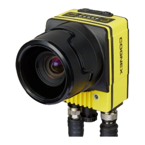
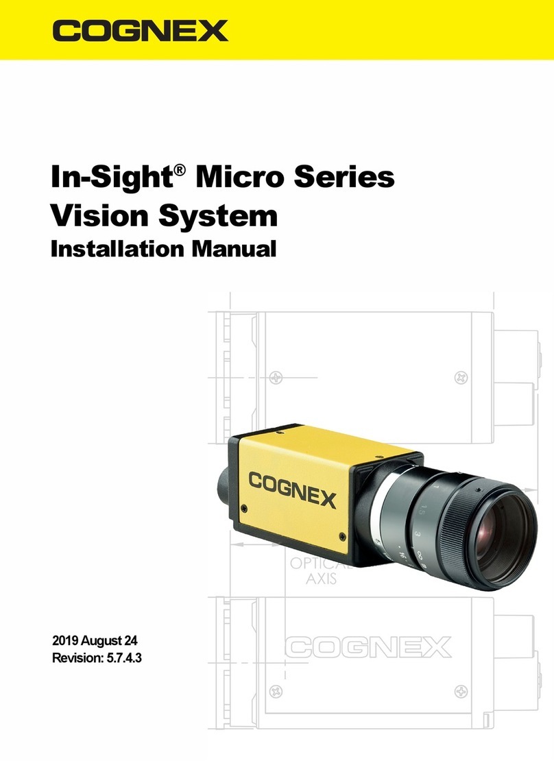
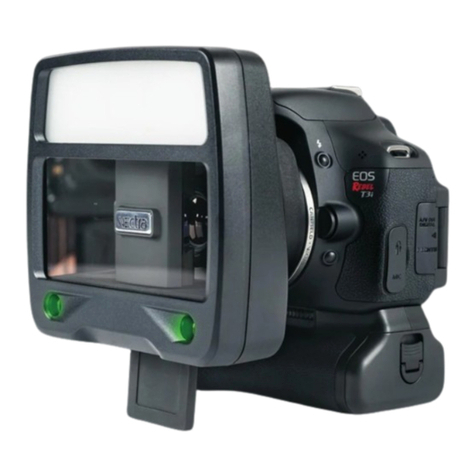
Cognex CAM-CIC-12-9M-IP67 User manual

GigE Area Scan Industrial Camera
User Manual
CAM-CIC-12-9M-IP67
CAM-CIC-12-9C-IP67
V1.0.0

1
CONTENTS
1WELCOME!..........................................................................................................................4
2SAFETY AND PRECAUTIONS.................................................................................................5
2.1 Definitions and Symbols .....................................................................................................5
2.2 General Safety Notices........................................................................................................6
3INSTALLING THE CAMERA HARDWARE.................................................................................7
3.1 Mounting.............................................................................................................................7
3.2 Connector............................................................................................................................7
3.3 GigE Cable............................................................................................................................8
3.4 GPIO Cable...........................................................................................................................8
3.5 Lens .....................................................................................................................................9
3.5.1 C mount lens.............................................................................................................9
3.5.2 Using a heavy lens.....................................................................................................9
3.6 IP67 Rating ..........................................................................................................................9
3.6.1 IP67 Cables...............................................................................................................9
3.6.2 GPIO Plug..................................................................................................................9
3.6.3 Lens Tube................................................................................................................10
3.6.4 Adapter Ring...........................................................................................................10
3.6.5 IP67 Kit....................................................................................................................10
4CONFIGURING THE CAMERA AND HOST SYSTEM............................................................... 11
4.1 Installing the Ethernet Driver ...........................................................................................11
4.2 Device Discovery and Enumeration ..................................................................................11
4.2.1 Camera IP Setup .....................................................................................................11
4.2.2 Setting Up Persistent IP...........................................................................................12
4.3 Bandwidth Management ..................................................................................................13
4.3.1 Jumbo Frames.........................................................................................................13
4.3.2 Receive Buffers .......................................................................................................13
4.3.3 Device Link Throughput Limit .................................................................................13
4.4 User Sets, Streamables, and File Access..........................................................................14
4.4.1 User Sets.................................................................................................................14
4.4.2 Streamables............................................................................................................14
4.4.3 File Access ..............................................................................................................14
5CAMERA SPECIFICATIONS.................................................................................................. 16
5.1 Power ................................................................................................................................16
5.2 Temperature......................................................................................................................16
5.3 GPIO Characteristics..........................................................................................................17
5.3.1 GPIO Pinout Diagram..............................................................................................17
5.4 GPIO Schematics...............................................................................................................18
5.4.1 Opto-isolated Input –GPIO Line 0...........................................................................18
5.4.2 Opto-isolated Output –GPIO Line 1........................................................................18

2
5.4.3 Non-isolated Input - GPIO Line 2.............................................................................19
5.4.4 Non-isolated Output - GPIO Line 2..........................................................................20
5.4.5 Non-isolated Input - GPIO Line 3.............................................................................20
5.4.6 Non-isolated Output - GPIO Line 3..........................................................................20
5.4.7 2.5V Output............................................................................................................21
5.5 LED Status .........................................................................................................................21
5.6 IR Filter..............................................................................................................................21
5.7 Shock and Vibration..........................................................................................................22
5.8 Specification Tests.............................................................................................................23
5.8.1 FCC..........................................................................................................................23
5.8.2 RoHS, REACH, and WEEE.........................................................................................24
5.8.3 CE............................................................................................................................24
6CAMERA FEATURES ........................................................................................................... 25
6.1 Image Processing Controls................................................................................................25
6.1.1 Defect Pixel Correction............................................................................................25
6.1.2 Gain ........................................................................................................................26
6.1.3 Color Processing.....................................................................................................27
6.1.4 White Balance ........................................................................................................28
6.1.5 Look-Up Table (LUT)................................................................................................28
6.1.6 Gamma...................................................................................................................29
6.1.7 Color Space Conversion and Correction..................................................................30
6.2 Image Format Controls .....................................................................................................30
6.2.1 Region of Interest (ROI)...........................................................................................30
6.2.2 Binning ...................................................................................................................31
6.2.3 Decimation.............................................................................................................32
6.2.4 Horizontal and Vertical Flip .....................................................................................32
6.2.5 Test Pattern.............................................................................................................33
6.3 Digital IO............................................................................................................................33
6.3.1 Configuring an Input Line........................................................................................33
6.3.2 TriggerOverlap........................................................................................................34
6.3.3 Configuring an Output Line.....................................................................................35
6.3.4 Turning on GPIO Voltage Output.............................................................................35
6.4 Chunk Data........................................................................................................................36
6.4.1 Extracting the Image CRC checksum with ChunkCRC..............................................36
6.5 Transfer Control.................................................................................................................36
6.5.1 Automatic Transfer Control ....................................................................................36
6.5.2 UserControlled Transfer Control ............................................................................38
6.6 Event Control.....................................................................................................................39
6.6.1 Exposure Start.........................................................................................................40
6.6.2 Exposure End..........................................................................................................40
6.6.3 Test .........................................................................................................................40
6.7 Firmware Update ..............................................................................................................40
6.7.1 Updating your Camera Firmware............................................................................41
3
7DEVICE NODES .................................................................................................................. 42
7.1 Acquisition Control ...........................................................................................................42
7.1.1 Acquisition Modes .................................................................................................42
7.1.2 Auto Exposure AOI .................................................................................................46
7.2 Action Control ...................................................................................................................47
7.3 Analog Control ..................................................................................................................47
7.4 Chunk Data Control ...........................................................................................................49
7.5 Color Transformation Control...........................................................................................50
7.6 Counter and Timer Control ...............................................................................................50
7.7 Defect Correction Control .................................................................................................51
7.8 Device Control...................................................................................................................52
7.9 Digital IO Control...............................................................................................................56
7.10 Event Control...................................................................................................................57
7.10.1 Event Acquisition Trigger Missed Data.................................................................58
7.10.2 Event Encoder 0 Restarted Data...........................................................................58
7.10.3 Event Encoder 0 Stopped Data.............................................................................58
7.10.4 Event Exposure End Data .....................................................................................59
7.10.5 Event Exposure Start Data....................................................................................59
7.10.6 Event Frame Dropped Data..................................................................................59
7.10.7 Event Frame Trigger Missed Data.........................................................................59
7.10.8 Event Temperature Out Of Range Data................................................................60
7.10.9 Event Test Data.....................................................................................................60
7.11 File Access Control...........................................................................................................60
7.12 I2C Access Control...........................................................................................................61
7.13 Image Format Control .....................................................................................................62
7.14 LUT Control......................................................................................................................64
7.15 Sequencer Control..........................................................................................................65
7.15.1 Supported Features: .............................................................................................65
7.15.2 Configuring a Sequencer Set.................................................................................65
7.16 Serial Access Control .......................................................................................................68
7.17 Software Signal Control...................................................................................................69
7.18 Test Control .....................................................................................................................69
7.19 Transfer Control...............................................................................................................69
7.20 Transport Layer Control...................................................................................................70
7.20.1 GigE Vision............................................................................................................71
7.20.2 PTP Control...........................................................................................................74
7.21 User Set Control ..............................................................................................................75

4
1WELCOME!
The CAM-CIC-12-9 is a ruggedized camera designed for industrial environments where dirt, dust or
water are present. Its lightweight, dust-proof, and water-resistant 29 x 29 mm camera enclosure
and lens tube makes this camera the smallest IP67-rated camera in the world. Its robust M12 and
M8 connectors and Sony Pregius CMOS sensor make this camera ideal for a wide variety of
industrial applications.

5
2SAFETY AND PRECAUTIONS
Follow these guidelines carefully before using your CAM-CIC-12-9.
2.1 Definitions and Symbols
Below are some warning, safety, and/or tips icons used in this document.
The Warning icon indicates a potentially hazardous situation. If not avoided, the situation can
result in damage to the product.
The ESD icon indicates a situation involving electrostatic discharge. If not avoided, the situation
can result in damage to the product.
The Help icon indicates important instructions and steps to follow.
The Light Bulb icon indicates useful hints for understanding the operation of the camera.
The Computer icon represents useful resources found outside of this documentation.

6
2.2 General Safety Notices
Powering the Camera
•The camera may not work, may be damaged, or may exhibit
unintended behavior if powered out- side of the specified power range.
•When using Power over Ethernet, the power sup- ply must comply
with IEEE 802.3af.
•When using the GPIO, the supplied power must be within the stated
voltage range.
See the Power section for further information.
Operating Temperature
•The camera may not work, may be damaged, or may exhibit
unintended behavior if operated outside of the specified temperature
range.
•See the Temperature section for further information.
Electrostatic Discharge
•Ensure proper precautions are implemented to prevent damage from
an electrostatic discharge.
Image Quality
•Dust or fingerprints on the sensor may result in a loss of image quality.
•Work in a clean and dust-free environment.
•Attach the dust cap to the camera when a lens is not mounted.
•Use only compressed ionized air or an optics cleaner to clean the
surface of the sensor window.

7
THREE
3INSTALLING THE CAMERA HARDWARE
3.1 Mounting
The camera is equipped with seven M3 mounting holes and six M2 mounting holes. One pair of
M2 and one pair of M3 holes are present on opposite sides of the lens mount surface. Two more
M2 holes are located on the bottom side of the camera towards the center.
If you are using a heavy lens, we recommend that you use the M3 mounting holes on the CAM-
CIC-12-9 to maximize the overall system rigidity.
The four corner-located M3 mounting holes on the bottom should be used whenever
possible for mounting instead of the M2 mounting holes for applications involving
vibration and applications using the IP67 lens tube.
3.2 Connector
The CAM-CIC-12-9 camera uses an x-coded 8-pin M12 connector with the following pin mapping
as seen from rear of the camera.

8
Pin Number (Camera Side)
Pin Description
1
BI_DA+
2
BI_DA-
3
BI_DB+
4
BI_DB-
5
BI_DD+
6
BI_DD-
7
BI_DC-
8
BI_DC+
3.3 GigE Cable
The CAM-CIC-12-9 camera uses an x-coded 8-position M12 connector (compliant with IEC 61076-
2-109) for Ethernet communication.
•For the best performance, a shielded Ethernet Cat5e or higher should be used. STP
shielding is recommended to minimize electromagnetic interference in environments
with harsh EMI conditions.
•An unshielded or lower grade/quality Ethernet cable may result in loss of camera
connection and/or lost and inconsistent image data.
•The maximum cable length from camera to host with no switch or repeater in between is
100 meters.
•Cognex recommends using qualified Ethernet cables from our web store.
3.4 GPIO Cable
The CAM-CIC-12-9 camera is equipped with an 8-pin General Purpose Input/Output (GPIO)
connector at the back.
•Cognex cameras are designed to use shielded or unshielded Ethernet cables.
•When using a shielded GPIO cable in an industrial setting, care must be taken to prevent
ground loops from forming between the camera chassis, Ethernet PoE power sourcing
equipment, IT infrastructure, and devices connected to GPIO.
•The GPIO cable can be shielded if terminated properly. An improper GPIO shield
termination scheme can cause substantial EMC emissions and immunity issues, induce
noise, and cause damage to the camera or equipment attached to the GPIO cable. Using a
shielded GPIO cable requires careful consideration of the system level EMC when shielded
Ethernet cables and PoE power are used.
•Only use shielded GPIO cables when powering the camera through GPIO. Be aware of the
power supply earth connection, and the Ethernet shielding termination, which is best
achieved by AC-coupling the Ethernet shield at the host chassis, or by using UTP cable.
•Any GPIO cable with M8 connector compliant with IEC 61076-2-104 will work.
•Cognex recommends using qualified GPIO cables from our web store.

9
Consult the GPIO Characteristics section for a GPIO pinout diagram.
3.5 Lens
Your camera has the lens mount shown below.
3.5.1 C mount lens
C mount lenses can be used on a C mount camera. According to the standard, the C mount
flange back distance is 17.53 mm.
3.5.2 Using a heavy lens
Mounting a heavy and long lens may damage the camera board. If the lens is considerably heavier
than the camera, the lens’ weight may exert excessive force on the lens mount attached to the
camera’s board, causing unexpected damage to the board and soldered components. If a heavy
lens is necessary for the production environment, it is recommended to use the lens as the
mounting point rather than the camera to avoid damage to the camera.
3.6 IP67 Rating
This section describes the parts required to achieve the IP67 rating for CAM-CIC-12-9.
3.6.1 IP67 Cables
Use IP67-rated cables with your CAM-CIC-12-9 to keep dust and water out of the connection ports.
Custom cables must be qualified by the integrator to maintain the IP67 rating.
Find IP67-rated GigE and GPIO cables on our website.
3.6.2 GPIO Plug
When the GPIO port on the CAM-CIC-12-9 is not in use, you must attach the GPIO plug to achieve
the IP67 rating.

10
3.6.3 Lens Tube
Without a lens tube, the CAM-CIC-12-9 achieves the IP50 rating, which is protection against dust
but not water. With a lens tube from Cognex, the CAM-CIC-12-9 achieves the IP67 rating, which is
dust proof and water resistant.
Custom lens tubes must be qualified by the integrator to maintain the IP67 rating.
3.6.4 Adapter Ring
The adapter ring is used to attach a lens tube on to the camera. When attaching the adapter ring,
the C-mount barrel on the CAM-CIC-12-9 should also extend past the ring by approximately 0.3
mm.
Use a rubber piece such as the Multipurpose Neoprene Rubber Strip from McMaster-
Carr (part number 1372N13) to assist in removing the adapter ring.
3.6.5 IP67 Kit
The IP67 kits from Cognex for CAM-CIC-12-9 consists of the following:
•An adapter ring with O-ring installed
•A lens tube
Find the IP67 kits on our website.
Pair a compact C mount lens with the associated lens tube to create a small IP67-rated
device. Note the optical format of the camera used.
The camera is not waterproof. It should not be submerged under water for
longer than 30 minutes.

11
4CONFIGURING THE CAMERA & HOST SYSTEM
4.1 Installing the Ethernet Driver
Cognex recommends updating to the latest version of your Ethernet adapter’s driver before
connecting your camera. You may need to navigate to the manufacturer’s website to find the
latest version of the driver.
4.2 Device Discovery and Enumeration
Cognex cameras are discovered and enumerated with the following process:
4.2.1 Camera IP Setup
There are three methods used by this camera to obtain an IP address:
•Persistent - The camera uses a fixed IP address.
•Dynamic Host Configuration Protocol (DHCP) - The camera is assigned an address from a
DHCP server.
•Link-Local Address (LLA) - The camera obtains an address in the Link-Local Address range
from 169.254.1.0 to 169.254.254.255.
A Link-Local Address is selected with a pseudo-random number generator, so an LLA
address cannot be reliably predicted. If you require a consistent IP address, you should
set up a persistent IP on the camera. For more information on Link-Local Address
selection, refer to Section 2.1 in RFC 3927.
The camera must be on the same subnet as the Ethernet adapter and have a
valid IP address before use.
Persistent IP and DHCP configurations can be disabled on the camera. The default camera
configuration is as follows:
Persistent IP Disabled
DHCP Enabled
LLA Enabled (always enabled)

12
Out of the box, the camera first attempts to connect using DHCP. If the camera is unable to
connect using DHCP, it will use Link-Local Addressing.
4.2.2 Setting Up Persistent IP
The following pseudocode demonstrates how to set up persistent IP:

13
//
Connect
to
camera
//
Get device node map
GevPersistentIPAddress
=
192.168.0.10;
//Enter persistent
IP address
for the
camera
GevPersistentSubnetMask = 255.255.255.0;
GevPersistentDefaultGateway = 192.168.0.1;
4.3 Bandwidth Management
4.3.1 Jumbo Frames
Cognex recommends enabling jumbo frames on your Ethernet adapter. A jumbo frame is an
Ethernet frame that is larger than 1500 bytes. Most Ethernet adapters support jumbo frames, but
it is usually turned off by default.
Enabling jumbo frames on the Ethernet adapter allows a packet size of up to 9000 bytes to be set on
the CAM-CIC-12-9. The larger packet size will enable optimal performance on high-bandwidth
cameras, and it usually reduces CPU load on the host system. In order to set a 9000-byte packet
size on the camera, the Ethernet adapter must support a jumbo frame size of 9000 bytes or
higher.
If you still experience issues such as lost packets or dropped frames, you can also try the following:
•Update the Ethernet adapter driver (you may need to enable jumbo frames again after
updating).
•Increase the receive buffer size in your Ethernet adapter properties.
•Reduce the DeviceLinkThroughputLimit value (this may reduce maximum frame rate).
4.3.2 Receive Buffers
A receive buffer is the size of system memory that can be used by the Ethernet adapter to receive
packets. Some Ethernet adapter drivers or the operating system itself may set the receive buffer
value to a low value by default, which may result in decreased performance. Increasing the
receive buffer size, however, will also increase system memory usage.
4.3.3 Device Link Throughput Limit
The Device Link Throughput Limit is the maximum available bandwidth for transmission of data
represented in bytes per second. This can be used to control the amount of bandwidth used by
the camera. The maximum available frame rate may decrease when this value is lowered since
less bandwidth is available for transmission.

14
4.4 User Sets, Streamables, and File Access
4.4.1 User Sets
The CAM-CIC-12-9 features two customizable user sets to load or save user-defined settings on the
camera. Accessing the user set named Default will allow loading or saving of factory default
settings. The CAM-CIC-12-9 will load the user set selected in UserSetDefault when powering up
or when reset.
If the camera is acquiring images, AcquisitionStop must be called before loading or
saving a user set.
4.4.2 Streamables
A camera feature marked as Streamable indicates that the feature’s current value can be stored to
and loaded from the streamables file.
4.4.3 File Access
The CAM-CIC-12-9 features persistent storage for generic file access on the camera. This feature
allows users to save and load a custom file up to 16 megabytes with UserFile. Users can also save
and load User Set contents to and from a file.
Loading new firmware on to the camera may overwrite existing UserFile contents

15
The following pseudocode demonstrates how to read from the camera using file access:
//
Connect
to
camera
//
Get device node map
FileSelector
=
UserFile1;
FileOpenMode = Read;
FileOperationSelector = Open;
FileOperationExecute();
//
Device sets FileOperationSelector
=
Close
//
Read custom
file
from camera
FileOperationExecute();
//
Device sets FileOperationSelector
=
Open
The following pseudocode demonstrates how to write to the camera using file access:
//
Connect
to
camera
//
Get device node map
FileSelector
=
UserFile1;
FileOpenMode
=
Write;
FileOperationSelector = Open;
FileOperationExecute();
//
Device sets FileOperationSelector
=
Close
//
Write custom
file to
camera
FileOperationExecute();
//
Device sets FileOperationSelector
=
Open
The following pseudocode demonstrates how to delete the user file on the camera using file access:
//
Connect
to
camera
//
Get device node map
FileSelector
=
UserFile1;
FileOperationSelector
=
Delete;
FileOperationExecute();
//
Power
cycle the
camera
DeviceReset();
User Sets, Streamables, and File Access functions do not load or save camera IP
configuration settings.

16
5CAMERA SPECIFICATIONS
5.1 Power
The CAM-CIC-12-9 can be powered via the Ethernet cable using Power over Ethernet (PoE) or the
GPIO using the pins described in the GPIO Characteristics section.
When using PoE, the power supply must comply with IEEE 802.3af. You can find recommended
parts to power the camera in our web store.
5.2 Temperature
The CAM-CIC-12-9 should be kept in the following storage, operating, and humidity conditions.
Storage Temperature -30 to 60°C
Operating Temperature -20 to 55°C ambient
Humidity Operating: 20% ~ 80%, relative, non-condensing
Placing the camera outside of these conditions may result in damage to the device.
The CAM-CIC-12-9 has a built-in temperature sensor that can be read by reading the
DeviceTemperature property.
The camera can get hot to touch if it has been streaming images for an extended
period of time.
DeviceTemperature can show values outside of the operating temperature range.
This is generally acceptable as long as the camera is kept within the specified
operating temperature range.

17
5.3 GPIO Characteristics
5.3.1 GPIO Pinout Diagram
The GPIO connector as seen from the rear of the CAM-CIC-12-9.
Pin Number
Pin Description
1
VAUX (12-24V DC Power Input)
2
Non-isolated bi-directional GPIO channel (Line 2)
3
VDD GPIO (2.5V Power Output) (Line 4)
4
Non-isolated bi-directional GPIO channel (Line 3)
5
GND (Camera GND)
6
OPTO GND (Opto-isolated Reference)
7
OPTO OUT (Opto-isolated Output) (Line 1)
8
OPTO IN (Opto-isolated Input) (Line 0)
Maximum supported input voltage: 24V
Maximum supported output voltage: 24V
Consult the Turning on GPIO Voltage Output section for enabling VDD.

18
5.4 GPIO Schematics
5.4.1 Opto-isolated Input –GPIO Line 0
Opto-isolated Input Measurements:
Volt-
age (V)
Max Rise
Delay (us)
Max Fall
Delay (us)
Max Rise
Time (us)
Max Fall Time
(us)
Min Pulse
Input (us)
Min
Input
High (V)
Min
Input
Low (V)
2.5
1
1
1
1
2
2.5
1.0
5
1
1
1
1
2
2.5
1.0
Sample values measured at room temperature. Results may vary with the temperature and setup.
Note that the maximum input voltage is 24V.
5.4.2 Opto-isolated Output –GPIO Line 1
Opto-isolated Output Measurements:
Volt-
age (V)
External
Resistor ()
Max Rise
Delay (us)
Max Fall
Delay(us)
Max Rise Time
(us)
Max FallTime
(us)
Current (mA)
Low Level
(V)
2.5
150
50
5
40
5
5.7
0.9
2.5
330
50
5
40
5
2.9
0.8
2.5
560
50
5
40
5
1.9
0.5
2.5
1k
50
5
40
5
1.2
0.3
5
330
50
5
50
5
6.6
0.9

19
5
560
50
5
50
5
4
0.7
5
1k
50
5
50
5
2.4
0.5
5
1.8k
50
5
50
5
1.4
0.4
12
1k
50
5
60
5
6
0.9
12
1.8k
50
5
60
5
3.4
0.9
12
2.7k
50
5
60
5
2.4
0.7
12
4.7k
50
5
60
5
1.5
0.5
24
1.8k
60
5
60
5
7.1
0.9
24
2.7k
60
5
60
5
4.7
0.9
24
4.7k
60
5
60
5
2.8
0.7
24
6.8k
60
5
60
5
2.1
0.6
Sample values measured at room temperature. Results may vary with the temperature and setup.
5.4.3 Non-isolated Input - GPIO Line 2
Non-isolated Input Measurements:
Voltage
(V)
Max Rise
Delay (us)
Max Fall
Delay (us)
Max Rise
Time (us)
Max Fall
Time (us)
Min Pulse
Input (us)
Min Input
High (V)
Min Input Low
(V)
2.5
1
1
1
1
2
2.5
0.5
5
1
1
1
1
2
2.5
0.5
Typical values measured at room temperature. Results may vary with temperature. Note that
the maximum input voltage is 24V.
This manual suits for next models
1
Table of contents
Other Cognex Digital Camera manuals

Cognex
Cognex MVS-8000 Series User manual

Cognex
Cognex ISC-7000 Series User manual

Cognex
Cognex ISC-8000 Series User manual

Cognex
Cognex CAM-CIC-3100-3-GC1 User manual

Cognex
Cognex In-Sight Micro Series User manual

Cognex
Cognex GigE CAM-CIC-4KL-28-G-1 User manual

Cognex
Cognex In-Sight 5000 Series User manual

Cognex
Cognex CAM-CIC-5000-20G-1 User manual