5
1Product Overview
1.1 Product Introduction
GigE area scan camera adopts high-performance sensor chip and realizes real-time
non-compressed image data transmission via GigE, which is compatible with any
application development tool which meets GigE Vision and GenICam standard. Max
transmission rate 1Gb/s can satisfy the requirements of transmission rate in most
industrial applications. It can work in various harsh environments stably with high
reliability and cost performance.
1.2 Product Features
Easy installation, convenient operation, support:
•Ethernet interface provides 1Gbps bandwidth, with max transmission distance up
to 100m.
•128MB on-board frame buffer for image data transmission.
•Supports software trigger, external trigger, mixed mode, free run mode.
•Supports sharpness, noise reduction, gamma correction, LUT, black level
correction, brightness, contrast and other ISP functions.
•Supports interpolation algorithm, white balance algorithm, color conversion
matrix, hue, saturation etc. for color camera.
•Supports several image data formats output, ROI, binning, mirror, etc.
•Conforms to GigE Vision V2.0 protocol and GenICam standard.
•Supports POE power supply and DC9V—24V wide-range power supply.
•Conforms to CE, FCC, UL and RoHS certification.
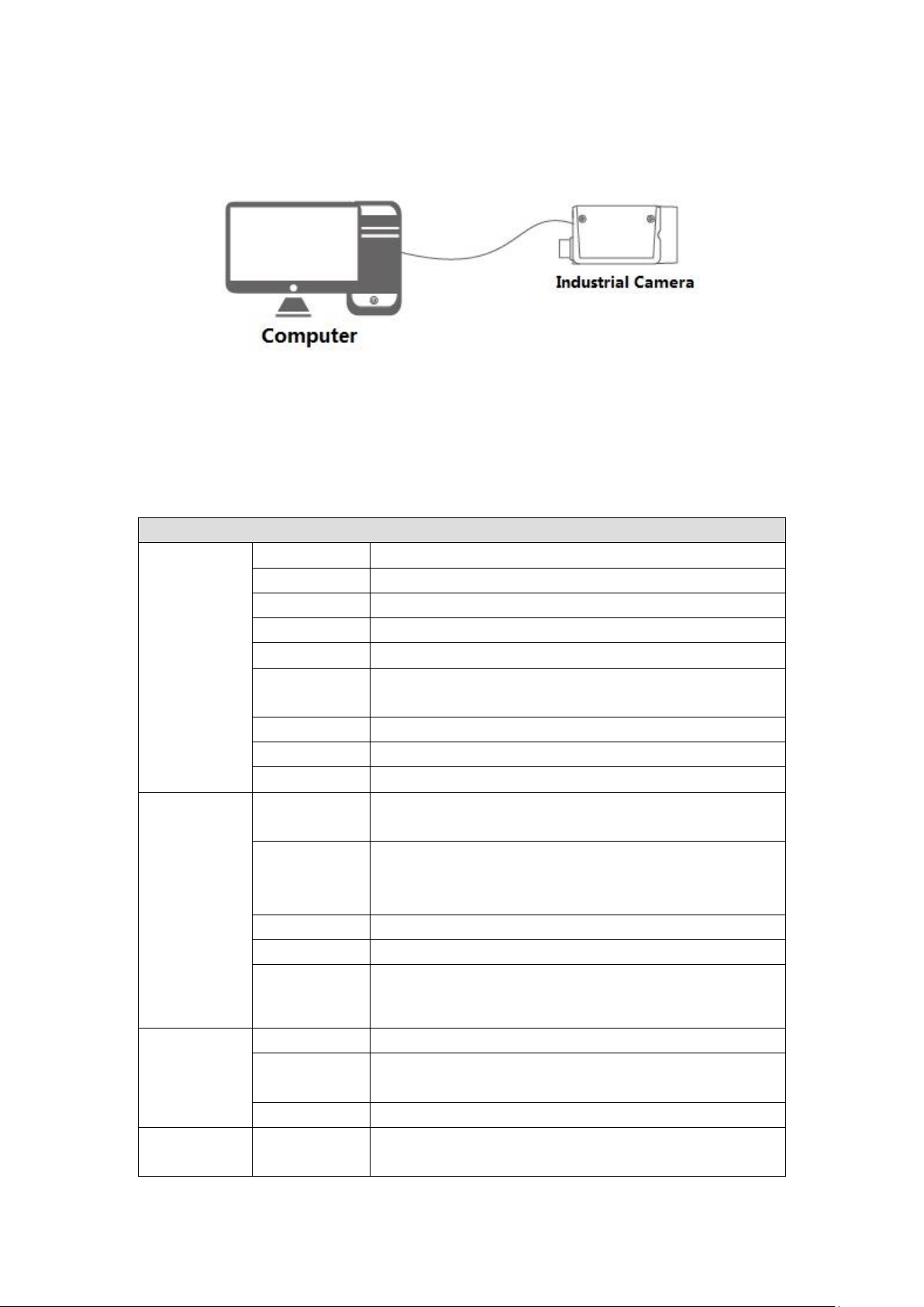
1.3 Typical Networking
The most typical networking mode of area scan camera is point-to-point connection,
which needs no other network medium between the host computer and industrial
camera. It can be connected through cable, please refer to Figure 1-1.