Colasit CMHV 900 User manual

COLASIT AG
Plastic construction
CH-3700 Spiez
Phone +41 (0)33 655 61 61 Fax +41 (0)33 654 81 61
TD-000 802-E
Edition 10/2019, Subject to alteration
Copyright by COLASIT AG Spiez
Page 1
OPERATION MANUAL CMHV 900 - 1250
High efficiency medium pressure –Plastic industrial fan
Agent :
For use in Ex zones
Not for use in Ex zones
COLASIT AG
Faulenbachweg 63
CH-3700 Spiez
Tel.: +41 (0)33 655 61 61
Fax: +41 (0)33 654 81 61
www.colasit.ch

COLASIT AG
Plastic construction
CH-3700 Spiez
Phone +41 (0)33 655 61 61 Fax +41 (0)33 654 81 61
TD-000 802-E
Edition 10/2019, Subject to alteration
Copyright by COLASIT AG Spiez
Page 2
Preface
This operating manual is the driver's license for operation of this COLASIT fan. It is the main source of
information and also the safety guideline. It deserves your full attention - please read it
carefully.
The contents of this operating manual are subject to change without notice in order to take technical
progress into account.
The manual contains icons that appear in the margin and indicate special dangers and important
instructions.
Very important note
Universally applicable warnings which concern your personal safety.
Indicates electrical dangers.
Indicates process control dangers.
The entire operating manual consists of 3 parts:
Part 1: General
Part 2: Components
Part 3: Certificates

COLASIT AG
Plastic construction
CH-3700 Spiez
Phone +41 (0)33 655 61 61 Fax +41 (0)33 654 81 61
TD-000 802-E
Edition 10/2019, Subject to alteration
Copyright by COLASIT AG Spiez
Page 3
Table of contents
Part 1: General ...........................................................................................................................................................4
1General................................................................................................................................................................4
1.1 Definition........................................................................................................................................................4
1.2 Production of COLASIT-fans.........................................................................................................................4
1.3 Warranty ........................................................................................................................................................4
1.4 Safety review.................................................................................................................................................5
1.5 Personnel qualifications.................................................................................................................................5
1.6 Possible emergencies....................................................................................................................................5
1.7 Safety officer (SO).........................................................................................................................................5
1.8 General risk matrix.........................................................................................................................................6
1.9 EU conformity of the COLASIT fan................................................................................................................7
1.10 Restrictions when commissioning .................................................................................................................7
1.11 General operation conditions.........................................................................................................................7
2Shipping, unpacking, inspection, storage............................................................................................................8
3Installation, configuration.....................................................................................................................................8
4Commissioning, initial startup, test run................................................................................................................9
4.1 Inspection of the installation and settings......................................................................................................9
4.2 Drive...............................................................................................................................................................9
4.3 Electrical installations, EMERCENCY STOP ................................................................................................9
5Operation...........................................................................................................................................................10
5.1 Safety instructions .......................................................................................................................................10
5.2 Putting out of operation ...............................................................................................................................10
6Maintenance, repair, cleaning ...........................................................................................................................10
6.1 Preparation ..................................................................................................................................................10
6.2 Performance ................................................................................................................................................11
7Spare parts........................................................................................................................................................12
8Operating instructions .......................................................................................................................................13
9Logbook.............................................................................................................................................................13
10 Disposal........................................................................................................................................................13
11 Troubleshooting............................................................................................................................................13
12 Retrofittable original accessories..................................................................................................................14
13 Fan identification...........................................................................................................................................15
Part 2: Units..............................................................................................................................................................15
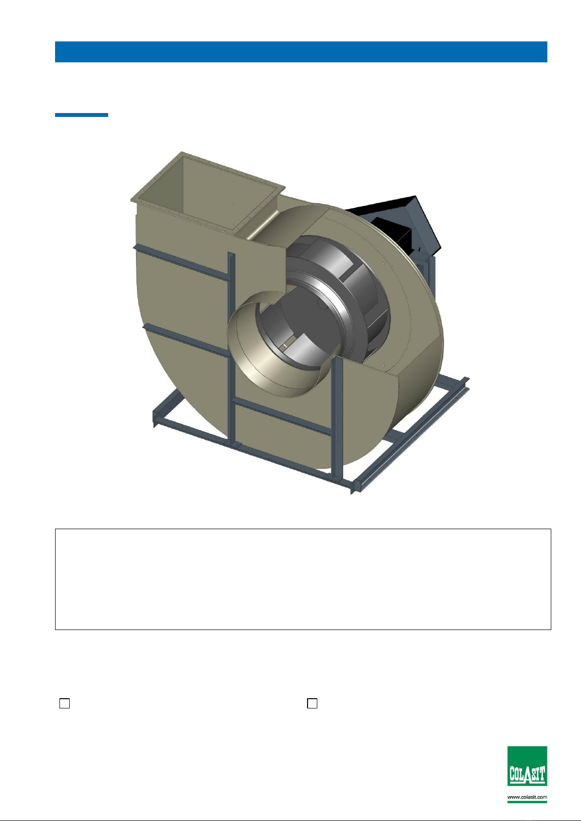
14 Design and function of the CMHV 900-1250................................................................................................15
15 Dimensional drawings...................................................................................................................................16
15.1 Dimensions of the CMHV 900-1250 with direct drive..................................................................................16
15.2 Dimensions of the CMHV 900-1250 with V-belt drive.................................................................................17
16 Assembly instructions...................................................................................................................................18
16.1 Assembly instructions CMHV 900–1250 with direct drive...........................................................................18
16.2 Assembly instructions for CMHV 900–1250 with V-belt drive.....................................................................19
17 Spare parts lists............................................................................................................................................21
17.1 Spare parts list for CMHV 900-1250 with direct drive .................................................................................21
17.2 Spare parts list for CMHV 900-1250 with V-belt drive.................................................................................22
Part 3: Certification...................................................................................................................................................23
18 Certifications.................................................................................................................................................23
18.1 EU declaration of conformity .......................................................................................................................23
18.2 Further certificates.......................................................................................................................................24

COLASIT AG
Plastic construction
CH-3700 Spiez
Phone +41 (0)33 655 61 61 Fax +41 (0)33 654 81 61
TD-000 802-E
Edition 10/2019, Subject to alteration
Copyright by COLASIT AG Spiez
Page 4
Part 1: General
1 General
OBLIGATIONS
Prior to any work done on or with the fan, we place you under an obligation to
read this operating manual and any further contractors’ operating instructions
carefully and through to the end.
Should anything not be clear, please get in touch with us immediately. Do not put
the fan into operation as long as uncertainties exist.
As soon as you start up the fan you confirm that you have read and understood
the operating manual.
After acquainting yourself with the fan and its operational performance together
with your production processes, we recommend that you make a note of the
different modes of operation in a “process instruction”.
Together with this operating manual, any acceptance documents, works acceptance certificates and the EU
Declaration of Conformity, the process instruction forms part of the complete system documentation.
For the fan, a separate risk analysis was conducted as a prerequisite for writing this operating
manual. Risks were evaluated and any remaining residual risks are pointed out in this operating
manual.
When extracting aggressive gases, it is imperative to review the suitability of the
materials:
▪Once the principal or the operator has notified us of the gas mix and the
maximum operating temperature, the suitability and any applicable
restrictions will be confirmed in the data sheet of COLASIT AG.
▪In the absence of a written notification with regard to the extracted
medium by the principal, the operator is responsible without limitation
for assessing the suitability for the operation of the ventilator.
1.1 Definition
The term "COLASIT fan" stands for a Swiss high-quality product and contains all the components and
individual parts as specified in the purchase order or in the material parts list, which, when assembled, form
a functional unit.
1.2 Production of COLASIT-fans
The fan was manufactured using modern production methods and was extensively tested both during
manufacture and as a finished product by the COLASIT quality assurance system. The methods and
processes used in production and monitoring correspond to the state of the art. The personnel entrusted
with production of the fan have the appropriate skills and possess valid qualifications.
All fans with engine are subjected to a successful test run at the manufacturer’s production facilities.
1.3 Warranty
Warranty ends on the date stated in the general terms of sale and delivery. Warranty is limited to the
delivery of spare parts or the repair of defective parts at the manufacturer’s factory. Any further claims or the
replacement of non-repairable or wear parts are excluded.
We guarantee the availability of spare parts identical in construction to the original over a period of 10 years
effective from the date of delivery.

COLASIT AG
Plastic construction
CH-3700 Spiez
Phone +41 (0)33 655 61 61 Fax +41 (0)33 654 81 61
TD-000 802-E
Edition 10/2019, Subject to alteration
Copyright by COLASIT AG Spiez
Page 5
COLASIT only guarantees the durability of materials on condition that technological data was available
before production.
Any change in the conditions of use is only permissible after approval by COLASIT; otherwise this will entail
loss of warranty.
Any changes or repair work during the warranty period may only be made by our fitters or with our written
consent.
We refer to the limitation of warranty noted in the “Motor“-section in the case where a frequency converter
supplied by a third party is fitted.
The fan must be deployed and used in accordance with the conditions mentioned
in this operating manual. Only in this way can its function be guaranteed and
dangers to persons and material be excluded during operation. We accept no
liability nor guarantee any claims for damages arising from nonobservance of this
manual or from inappropriate operation
1.4 Safety review
After installing the fan, we recommend the operator conducts a review of the entire operational environment.
In this way it can be guaranteed that neither the fan will suffer damage nor that the fan will cause any
damage.
1.5 Personnel qualifications
The fan may only be put into operation, handled, operated, maintained and cleaned by trained personnel
who are authorised (and competent) to carry out such work.
The personnel must possess the appropriate skills needed to operate the fan and be familiar with the effects
of the reactions caused by the fan.
The personnel qualified to operate the fan must be able to react adequately and correctly in case of a fault or
an emergency.
1.6 Possible emergencies
An emergency may result from the bursting or melting of plastic components as a result of mechanical
damage or chemical and thermal influences. In this case, parts may fly off or vapour may be produced that
may be hot, corrosive, poisonous, irritating or inflammable (e.g. hydrochloric acid vapour occurring from
burning PVC).
There may be a danger of fire under certain circumstances.
For the choice of the correct fire-extinguishing devices and the positioning of the firefighting equipment,
please follow the recommendations of your local fire station.
1.7 Safety officer (SO)
The function of the safety officer or his representative is defined in the operating company’s organisational
chart. The name of the person must be known to all personnel who are responsible for the fan.
The operating company defines his competencies and his area of responsibility.
The safety officer approves the fan for operation.

COLASIT AG
Plastic construction
CH-3700 Spiez
Phone +41 (0)33 655 61 61 Fax +41 (0)33 654 81 61
TD-000 802-E
Edition 10/2019, Subject to alteration
Copyright by COLASIT AG Spiez
Page 6
1.8 General risk matrix
Operation
The safety regulations prevailing at the operator’s location are mandatory and
must be observed at all times. Before making an intervention, the process must
be stopped, i.e. all mechanical movement must be stopped and it must be
ensured that no automatic motion can occur.
Missing safety devices
If the fan is equipped with safety devices, they may neither be modified nor
removed. Further safety devices of suitable design must be fitted by the operator
and are subject to his control.
Disregard of safety precautions
Please implement all safety measures so that the fan, together with its associated
equipment, can operate properly and any danger to persons, materials and
products can be excluded.
Putting the fan out of operation
In the case of damage to or failure of safety devices, the fan must be stopped
and put out of operation. It may only be put into operation again when the safety
devices are fully functional again.
Overpressure
If the fan is operated in overpressure conditions with normal seals, there is a
danger of gas escaping.
For operation in overpressure conditions, special seals must be fitted.
Electricity
When any work is carried out on the fan, the electric motor must be deenergised
and secured to prevent it from switching on. The main power switch must be
secured against operation by third parties using a lockable device (e.g. padlock)
by the persons working on the fan. Full disconnection of the motor is only
permissible in case of complete removal!
The safety regulations for work on electrical equipment prevailing at the place of
operation must be observed at all times and be available for reference at the
place of operation.
Electrostatic charge
Media flowing through the plastic components may cause the buildup of
electrostatic charge. These are harmless to persons who do not react to electrical
impulses in the body
Unsuitable materials
Through the use of inappropriate materials, the fan and/or parts may be damaged
or become non-functional. Please always use original spare parts and contact the
manufacturer in any case of doubt.

COLASIT AG
Plastic construction
CH-3700 Spiez
Phone +41 (0)33 655 61 61 Fax +41 (0)33 654 81 61
TD-000 802-E
Edition 10/2019, Subject to alteration
Copyright by COLASIT AG Spiez
Page 7
Dangerous media
Depending on the mode of operation, fan parts may come in contact with
dangerous media.
Work on the fan or carrying out maintenance work is not allowed during
operation. Before carrying out any work, any dangerous media must be removed
from the system and, when required, must be neutralized and secured in such a
way that an inflow of dangerous media is prevented.
1.9 EU conformity of the COLASIT fan
The fan was designed, built and tested to Directive 2006/42/EC.
In addition to this EU Directive and EN standards which have the equivalent status of a Swiss standard,
Swiss safety and accident-prevention regulations have also been taken into account.
An EU Declaration of Conformity in terms of the guidelines 2006/42/EC on machines will be issued
along with the fan.
1.10 Restrictions when commissioning
We stipulate that putting into operation is prohibited as long as the fan, including
all parts belonging to it or equipment connected to it, has not been installed and
checked out and until the operating manual has been read completely before
commissioning.
We stipulate that the fan may only be put into operation when the safety inspector
has given his approval. He is obliged to record this approval in a protocol.
The disregard of these stipulations constitutes negligence.
1.11 General operation conditions
The permissible operating conditions are indicated on the manufacturer‘s plate.
The fan is not suitable for the transport of solids in the air flow. This operating
mode will lead to the destruction of the fan.
The ducts on the intake and delivery sides must always be open. A closed duct will lead to a rise in
temperature which could cause the destruction of the fan.
The minimum air speed through the fan is 5 meters per second.
The maximum air speed may not exceed 30 meters per second through the fan.
The standard motors are designed for normal operating conditions (ambient temperature +40°C,
altitude below 1000 m above sea level, air pressure up to 1050 hPa). In case of any divergence from
these conditions, please contact COLASIT.
Compliance with these operating conditions is the responsibility of the operator.

COLASIT AG
Plastic construction
CH-3700 Spiez
Phone +41 (0)33 655 61 61 Fax +41 (0)33 654 81 61
TD-000 802-E
Edition 10/2019, Subject to alteration
Copyright by COLASIT AG Spiez
Page 8
2 Shipping, unpacking, inspection, storage
The fan is completely assembled and can be delivered in a closed film wrapping.
Please make sure the delivery corresponds to the shipping documents.
Please examine the packaging for external damage and report any damage
immediately to the transport company, the supervisor and the manufacturer.
Please handle the fan with care. During transportation, only apply strain on the steel parts. Plastic is
sensitive to impact and knocks, especially in the temperature range under +5°C.
When the film is removed, the intake and pressure nozzles are open and
unprotected against the intrusion of foreign objects. Therefore, please do not
remove the protective film until shortly before final installation.
Storage
If the fans are not put into operation immediately, store them in a clean dry place
where they are protected from impacts, vibrations, and temperature fluctuations
and where the air humidity is under 90%.
If these storage conditions are not available, switch the fans on at regular intervals
to exclude the risk of condensate forming. Before switching on, unscrew the
condensate drain plugs each time and replace them afterwards.
Store the fan in a dry, weather-protected place and cover with a tarpaulin to protect it from dust and
soiling.
If stored for over one year, test whether the fan bearings rotate freely before putting into operation.
3 Installation, configuration
Before installation, check whether all the locking screws (including the motor
screws) are tightened properly.
Check the electrical connections if wired at the factory.
Before installation, check that there are no foreign bodies in the coil or in the
intake and pressure connections.
The fan must be installed at a location provided and prepared by the customer and must be secured and
connected in such a way that any possible vibration occurring can be absorbed by the vibration dampers
supplied by COLASIT.
If no ducting is foreseen on the intake side, the intake connection should be protected by a sturdy protective
grating (10mm mesh) to be provided by the customer.
Connection ducting on the pressure side must be routed to prevent the backflow of foreign bodies, rainwater
or condensate into the fan. To ensure this, please use the COLASIT condensate drain nozzles.
Due to the possibility of noise nuisance, we recommend that the fan should not be installed in the
immediate vicinity of workplaces.

COLASIT AG
Plastic construction
CH-3700 Spiez
Phone +41 (0)33 655 61 61 Fax +41 (0)33 654 81 61
TD-000 802-E
Edition 10/2019, Subject to alteration
Copyright by COLASIT AG Spiez
Page 9
4 Commissioning, initial startup, test run
The fan should only be put into operation after inspection and approval by the
safety officer.
4.1 Inspection of the installation and settings
Check list:
Prior to commissioning and initial start-up, it must be guaranteed that
the fan is installed vibration-free and mechanically secured,
all components are cleaned both on the inside and the outside and are free from foreign bodies,
all intake and pressure ducts connections are leak-proofed
all rotating parts are protected against unintentional contact,
the electrical connections are installed and their function tested,
a lockable main control switch is available to which the fan is connected
the EMERGENCY-STOP equipment is functionally tested,
the safety inspector has made sure that safety equipment exists,
the operating personnel is familiar with the operating manual,
the safety inspector has given his approval fort he operation of the installation and that no external
persons are present in the plant area
If envisaged by procedural regulations provided by the operator, minutes have to be taken on the
commissioning work, including the observance of the check list.
4.2 Drive
The fan is driven by an electric motor which is connected to the impeller shaft either directly or via a V-belt.
The motor electrical specifications are indicated on the motor’s rating plate or in the motor manufacturer’s
data sheet.
When speed is controlled by means of a frequency converter, the maximum speed is limited by COLASIT to
the value indicated on the manufacturer’s rating plate.
If the frequency converter is not supplied by COLASIT, the operator is
responsible for compliance with the maximum speed limitation. In this case,
COLASIT will not assume any liability for damage that may be attributed to
exceeding the maximum speed.
In the case of motor outputs over 3kW, we recommend the use of a soft starter or a star-delta connection.
4.3 Electrical installations, EMERCENCY STOP
The electrical installations may only be carried out by an authorised electrician in accordance with the
regulations prevailing at the site at which the fan is installed.
To interrupt the power supply, an EMERGENCY STOP switch must be provided. It is advisable to mount this
switch in the vicinity of the emergency exit.
Please request confirmation from an in-house electrician that the electrical installations were carried out and
tested in accordance with regulations, that all functions were tested (or simulated) and that the rotational
direction is correct.

COLASIT AG
Plastic construction
CH-3700 Spiez
Phone +41 (0)33 655 61 61 Fax +41 (0)33 654 81 61
TD-000 802-E
Edition 10/2019, Subject to alteration
Copyright by COLASIT AG Spiez
Page 10
Warning
Please request confirmation from an in-house electrician that the electrical
installations were carried out and tested in accordance with regulations, that all
functions were tested (or simulated) and that the rotational direction is correct.Do
not turn power on or off without prior warning to persons in the area where the
fan is operating. Switching operations must be co-ordinated with other functions
in the working area of the fan.
5 Operation
5.1 Safety instructions
The fan must be operated according to this manual. This will avoid the
occurrence of any damage.
Supervision
The fan must not be operated unattended as long as it conveys substances
whose reactions are unknown or if unexpected reactions are anticipated.
If supervision must be withdrawn for operational reasons, this must be reported to
the safety officer and the system must be secured in such a way that no
unauthorized intervention can be carried out. The safety officer must decide on
issues regarding supervision.
5.2 Putting out of operation
An internal process instruction must regulate the work to be carried out as well as the preparatory work for
putting back into operation (e.g. cleaning).
6 Maintenance, repair, cleaning
6.1 Preparation
Before any work is carried out on the fan, the fan must be set to its "safety
position".
The „safety position“ is defined as follows:
- The drive must be currentless and the main switch secured against switching on,
-The fan impeller can be manually rotated,
- Fan must be flushed with fresh air and be condensate-free,
- Fan must be at room temperature,
- Personal protective equipment must be available and it must be worn. (Use of protective gloves
because of sharp edges, ear protectors if necessary).
- A sign, e.g. „Under-repair“, must be attached to the system,
- The safety devices may be removed,
- The work to be carried out must not be done under time pressure,
- The general and specific regulations on accident prevention as well as the EKAS guidelines
(Switzerland) must be observed,
- The safety officer must be informed about the nature and course of the work,
If the intake and delivery ducts of the fan are dismounted for a longer period of time, the openings must be
closed off.

COLASIT AG
Plastic construction
CH-3700 Spiez
Phone +41 (0)33 655 61 61 Fax +41 (0)33 654 81 61
TD-000 802-E
Edition 10/2019, Subject to alteration
Copyright by COLASIT AG Spiez
Page 11
6.2 Performance
The fan must be maintained in accordance with the Maintenance Plan below. The maintenance work carried
out must be noted down in the logbook (see the section on Logbook).
Every week
Every month
Every year
•Make a visual inspection of fan
for damage, leaks, corrosion
and attachment.
•Check the smooth running of
the fan and electric motor.
•Check state and tension of the
V-belt and replace if necessary.
•Check the impeller and casing
for deposits and clean if
necessary.
•Check the shaft bearing for
smooth running and
vibrations. Bearing
maintenance -> see chart
below for regreasing intervals.
•Remove any dust deposits on
the fan and motor.
•Check the flexible transitions
from fan to duct system for
leaks and state.
•Check the function of the
condensate nozzle.
•Check the state of the
vibration dampers.
•Check the state of the hub
gasket (if fitted).
•Carry out a thorough cleaning
of the entire fan (including
impeller).
•Check the parts in contact
with the conveyed medium
for corrosion.
•Check the minimum clearance
between the impeller and
casing (minimum 1% of
intake diameter, maximum
20mm).
•Measure the vibrations at
bearings (KA) or motor (DA).
Alarm according to ISO
14694: ≤3.7 kW, categorie
BV-2: 14.0 mm/s (r.m.s.) or
≤300 kW, categorie BV-3:
11.8 mm/s (r.m.s.).
•Check the safety devices (e.g.
splinter protection or intake
grating) for condition and
function.
•Check the stands for damage
and stability.
•Check all screw unions for
firm seating.
Normally the bearings are designed for a service life of 40,000 hrs. After this
period the bearings must be replaced. The service life of the bearings is reduced
when subjected to increased requirements (e.g. high temperature, aggressive
ambient air or operation with frequency converter).
On drives with V-belts, check the tension regularly and monitor the belts closely particularly during the first
weeks of operation. This also applies after long periods of downtime. Excessive tension leads to bearing
damage, insufficient tension leads to slip, wear and frictional heat.
After replacing a V-belt, check the tension after 1 to 4 hours of operation and retension as necessary.
The fan bearings are maintenance-free and the grease filling is designed for about 20,000 hours of
operation.
The bearing temperature of 70ºC may not be exceeded. In cases of high stress (environment) the grease
quantity loses its lubricity over time due to mechanical stresses, ageing and increasing contamination. The
bearings must then be greased according to the following table:

COLASIT AG
Plastic construction
CH-3700 Spiez
Phone +41 (0)33 655 61 61 Fax +41 (0)33 654 81 61
TD-000 802-E
Edition 10/2019, Subject to alteration
Copyright by COLASIT AG Spiez
Page 12
Components which are not intended for repair by the operator must be sent to the manufacturer or agent for
repair or replacement (e.g. damaged impeller).
Your agent or COLASIT
also offers customer services
Manufacturer
COLASIT AG
P.O. 85
CH 3700 Spiez / Switzerland
Tel.:
0041 (0)33 655 61 61
Fax.:
0041 (0)33 654 81 61
e-mail
info@colasit.ch
Agent
see front page
Deposits on the impeller and soiling lead to imbalance and as a result to
vibrations with undesirable side effects.
If vibration occurs, switch the fan off immediately
Contamination and encrustations should be removed with a soft tool without damaging the surface (e.g. with
a wooden spatula or scraper).If possible, use water and a household cleaning agent
Solvents can corrode the material. These may only be used with the written
consent of COLASIT.
To carry out cleaning work, we recommend the production of a process instruction
7 Spare parts
Please identify components by means of the position and drawing numbers as well as the order number and
type designation.
Use only original spare parts. Our warranty becomes null and void if other or unapproved components are
used.
Please address your spare parts order to our customer service department.

COLASIT AG
Plastic construction
CH-3700 Spiez
Phone +41 (0)33 655 61 61 Fax +41 (0)33 654 81 61
TD-000 802-E
Edition 10/2019, Subject to alteration
Copyright by COLASIT AG Spiez
Page 13
8 Operating instructions
To operate the fan, we recommend the production of process instructions. These documents are intended to
simplify repetitive workflows, reduce the risk of incorrect operation and are a valuable aid for training and
when personnel changes occur.
If the fan must be qualified, process instructions are an absolute prerequisite.
You will find important instructions on how to produce process instructions in various chapters of this
operating manual.
To help ensure the safe operation of the fan, COLASIT offers the service of
reviewing process instructions prepared by the operator
9 Logbook
For your own safety and as an aid to personal responsibility, we recommend the keeping of a logbook for the
entire period during which the fan is in service.
All events should be recorded in the logbook.
In case of damage and also in case of an accident, this document is the first source of information.
For example, enter the date and your signature:
- Start and end of a work cycle
- Special events, even if they do not concern the fan itself (e.g. power failure, alarm)
- Change of supervision staff (e.g. in case of shift operation),
- Repairs carried out and spare parts installed,
- Putting out of operation,
- Special instructions,
- etc.
10 Disposal
Before disposing of plastics and other components (complete or as broken parts), please clean them as
necessary to avoid any danger to the environment.
Dispose of the components properly. Instruct a waste disposal company to do this or return them to us for
disposal.
11 Troubleshooting
If faults occur, we recommend you identify and clear them using the following table.
If the fault cannot be cleared, please contact our customer service department.
Fault
Possible causes
Remedy
Fan not running smoothly
Impeller imbalance
Rebalance by specialist
company
Impeller caked up
Clean carefully rebalance if
necessary
Material corrosion on impeller
due to aggressive conveyed
medium.
Consult the manufacturer
Impeller deformed due to high
temperature.
Consult the manufacturer.
Install new impeller.
Check bearings
V-belt drive not correctly
aligned.
Adjust belt drive
V-belt torn or damaged
Normal wear and tear
Replace V-belts in sets
V-belt pretensioned too strongly
Tension replacement belt to
manufacturer’s specifications

COLASIT AG
Plastic construction
CH-3700 Spiez
Phone +41 (0)33 655 61 61 Fax +41 (0)33 654 81 61
TD-000 802-E
Edition 10/2019, Subject to alteration
Copyright by COLASIT AG Spiez
Page 14
Fault
Possible causes
Remedy
V-belts slip due to
Incorrect pretension
Check belt tension and retighten
if necessary
Foreign bodies or soiling in
grooves or pulleys
Clean pulleys and check belt
profile
Leak at shaft bushing
Seal not suitable for application
Consult the manufacturer
Leak on sleeves
Sleeves defective
Replace sleeves
Tensioning straps not tight
enough
Retighten tensioning straps
Fan output too low
Incorrect rotation direction of
impeller
Change rotation direction
Pressure losses in ducts too
high
Change duct arrangement
Restrictors not or only partly
open
Check opening on site
Intake or pressure duct blocked
Remove blockage
Fan fails to reach its rated
speed
Electrical switching mechanisms
incorrectly adjusted
Check motor protection setting
and reset if necessary
Motor winding defective
Please consult the manufacturer
Drive motor drive not correctly
designed
Please consult manufacturer to
verify starting torque
Grinding noises when fan is
running or starting
Intake duct fitted under tension
Remove intake duct an realign
Rise in temperature of roller
bearings
Bearing was not greased
Change bearing and grease at
regular intervals as stipulated in
the maintenance instructions
Bearing was excessively
greased
Change bearing, otherwise as
above
Dust in bearing
Renew seal
12 Retrofittable original accessories
If not already a part of our scope of supply, these original parts are available ex stock when ordered.
- Sleeve round with fixing bands, stainless
- Sleeve round with flange on one side with fixing bands
- Sleeve rectangular with flanges on both sides
- Condensate drains
- Vibration dampers
- Splinter protection
- Lip seal
- Weather-proof motor cover for outside installation
- Inspection hole
- Frequency converters

COLASIT AG
Plastic construction
CH-3700 Spiez
Phone +41 (0)33 655 61 61 Fax +41 (0)33 654 81 61
TD-000 802-E
Edition 10/2019, Subject to alteration
Copyright by COLASIT AG Spiez
Page 15
13 Fan identification
The following rating plate is affixed to each COLASIT fan:
1Manufacturer
2Field for CE marking and applicable standards
3ATEX-identification, for details see the section on Explosion Protection
4Fan specifications: fan type, casing design, material of casing and impeller, order number and date of
manufacture.
5 Technical specifications
Part 2: Units
14 Design and function of the CMHV 900-1250
All impellers in this series are balanced to better than Q 6.3 according to ISO 21940.
The casing with its thermoplastic rear panel is screwed onto the support base and can be easily dismantled
for inspection or cleaning purposes.
The fans are available in 2 standard designs
•Direct drive
•V-belt drive
As a basic principle, plastic fans are to be installed on the intake side in order to avoid leaks.

COLASIT AG
Plastic construction
CH-3700 Spiez
Phone +41 (0)33 655 61 61 Fax +41 (0)33 654 81 61
TD-000 802-E
Edition 10/2019, Subject to alteration
Copyright by COLASIT AG Spiez
Page 16
15 Dimensional drawings
15.1 Dimensions of the CMHV 900-1250 with direct drive
CMHV
900
1000
1120
1250
A
964
1062
1200
1265
B
900
1000
1120
1120
C
710
800
900
1000
D
900
1000
1120
1250
Ød
900
1000
1120
1250
E
1081
1197
1347
1405
F
907
1007
1133
1155
G
1255
1387
1561
1655
H 0°
1250
1400
1600
1800
H 45°
1250
1400
1600
1600
H 90°
1250
1250
1400
1400
H 135°
1250
1250
1250
1400
H 270°
1600
1800
2100
2100
H 315°
1400
1600
1800
1800
I
1000
1100
1220
1350
J
560
630
710
800
K
810
900
1000
1100
L
1475
1520
1570
1620
M
1100
1100
1100
1100
N
772
772
772
772
P
50
50
50
50
Q
648
693
743
793
R
1915
2005
2105
2205
Øs
12
12
12
12
T
27.5
27.5
27.5
27.5
U
1545
1545
1545
1545
V
1600
1600
1600
1600
W
146
146
146
146

COLASIT AG
Plastic construction
CH-3700 Spiez
Phone +41 (0)33 655 61 61 Fax +41 (0)33 654 81 61
TD-000 802-E
Edition 10/2019, Subject to alteration
Copyright by COLASIT AG Spiez
Page 17
15.2 Dimensions of the CMHV 900-1250 with V-belt drive
CMHV
900
1000
1120
1250
A
964
1062
1200
1265
B
900
1000
1120
1120
C
710
800
900
1000
D
900
1000
1120
1250
Ød
900
1000
1120
1250
E
1081
1197
1347
1405
F
907
1007
1133
1155
G
1255
1387
1561
1655
H 0°
1250
1400
1600
1800
H 45°
1250
1400
1600
1600
H 90°
1250
1250
1400
1400
H 135°
1250
1250
1250
1400
H 270°
1600
1800
2100
2100
H 315°
1400
1600
1800
1800
I
1000
1100
1220
1350
J
560
630
710
800
K
810
900
1000
1100
L
1665
1710
1760
1810
M
1100
1100
1100
1100
N
772
772
772
772
O
1475
1520
1570
1620
P
50
50
50
50
Q
648
693
743
793
R
1915
2005
2105
2205
Øs
12
12
12
12
T
27.5
27.5
27.5
27.5
U
2145
2145
2145
2145
V
2200
2200
2200
2200
W
146
146
146
146

COLASIT AG
Plastic construction
CH-3700 Spiez
Phone +41 (0)33 655 61 61 Fax +41 (0)33 654 81 61
TD-000 802-E
Edition 10/2019, Subject to alteration
Copyright by COLASIT AG Spiez
Page 18
16 Assembly instructions
16.1 Assembly instructions CMHV 900–1250 with direct drive
1. Screw individual parts of fan support together.
Fit motor on support.
2. Fit rear panel to support. Slide impeller onto shaft.
3. Screw housing to rear panel.
4. Screw bracket to base frame.
Fit housing brace at front and rear. Position impeller, tighten and
fit hub cap.
Dismantling in the same way but in reverse order

COLASIT AG
Plastic construction
CH-3700 Spiez
Phone +41 (0)33 655 61 61 Fax +41 (0)33 654 81 61
TD-000 802-E
Edition 10/2019, Subject to alteration
Copyright by COLASIT AG Spiez
Page 19
16.2 Assembly instructions for CMHV 900–1250 with V-belt drive
1. Screw individual parts of fan support together.
Fit bearing units and shaft on support. Fix motor to
support.
2. Fit rear panel to support. Slide impeller on drive
shaft.
3. Screw housing to fan rear panel.
4. Screw bracket to base frame.
Fit housing brace at front and rear. Position
impeller, tighten and fit hub cap.

COLASIT AG
Plastic construction
CH-3700 Spiez
Phone +41 (0)33 655 61 61 Fax +41 (0)33 654 81 61
TD-000 802-E
Edition 10/2019, Subject to alteration
Copyright by COLASIT AG Spiez
Page 20
5. Fit V-belt protection panel and V-belt drive.
6. Mount V-belt and shaft protection.
Dismantling in the same way but in reverse order
This manual suits for next models
3
Table of contents
Other Colasit Fan manuals

Colasit
Colasit CMHV 450 User manual

Colasit
Colasit CRDV 200 User manual

Colasit
Colasit CMVpro 125-400 ATEX User manual

Colasit
Colasit CRDV Series User manual

Colasit
Colasit CRDV 200-315 User manual

Colasit
Colasit CHVN 800 User manual

Colasit
Colasit CDVA 400 User manual

Colasit
Colasit CCV 75 User manual

Colasit
Colasit CMV 450 User manual

Colasit
Colasit CHVN 315 User manual