Cole Parmer 52411-26 User manual

52411Vacuumoven_ver_1.0 as version
www.coleparmer.com
Maximum Theoretical Vacuum / Elevation Chart
Elevation
(Feet)
Vacuum Level
inHg
mmHg
PSI
kPa
Torr
10,000
20.58
522.7
10.10
69.64
522
9,000
21.39
543.3
10.50
72.40
543
8,000
22.23
564.6
10.91
75.22
564
7,000
23.1
586.7
11.34
78.19
586
6,000
23.99
609.3
11.78
81.22
609
5,000
24.90
632.5
12.23
84.33
633
4,500
25.37
644.4
12.46
85.91
644
4,000
25.84
656.3
12.69
87.49
656
3,500
26.33
668.8
12.93
89.15
669
3,000
26.82
681.2
13.17
90.81
681
2,500
27.32
693.9
13.41
92.46
694
2,000
27.82
706.6
13.66
94.19
706
1,500
28.33
719.6
13.91
95.91
719
1,000
28.86
733
14.16
97.63
732
500
29.38
746.3
14.43
99.49
746
Sea Level
29.92
760
14.696
101.33
760
1. User Warning
WARNING
Failure to follow all warnings and instructions could result in serious injury. Your safety is
very important to us, so we urge you to take the following precautions when using this
product.
We are not responsible for injury or damage caused by misuse.
•Always use eye protection and appropriate thermal gloves during use.
•Always unplug the oven when performing maintenance or moving the oven.
•Do not heat flammable materials or materials that may outgas corrosive compounds.
•Ensure that items and materials heated by the oven are heated below their flash or
ignition point.
•Do not unplug the oven when it is running. You must switch the unit off using the
power switch located on the front of the unit, then unplug.
•Oven must be used in a stable environment (77°F @ ≤85%RH).
•Oven must not be stored around corrosive chemicals or moist environments that
could damage the electronics and hardware.

52411Vacuumoven_ver_1.0 as version
www.coleparmer.com
•Never use a damaged or modified power cable. Do not use on an ungrounded circuit.
Failure to follow warning could result in electric shock.
•Always close the vacuum valve PRIOR to turning off the vacuum pump. As with our
other vacuum products, this could result in pump oil being pulled into the oven.
•Avoid corrosive chemicals when cleaning the gasket, or oven chamber.
•Take caution when removing items as the oven, door, and sample will be hot. Always
use proper personal protection.
•A high temp 212F+ run will burn out any residue left from the assembly process.
1.2 Electrical Installation
THIS EQUIPMENT MUST BE EARTHED
Before connection please ensure that the line supply corresponds to that shown on the rating plate located on
the back of the unit.
Power requirements
Model
Wattage
Model
Wattage
52411-26
1050W
52411-28
1960W
52411-27
1050W
52411-29
1960W
Cord Connected Models
The unit will be supplied with a mains lead fitted with either US, EU, UK or Indian plug. Should the lead not be
suitable for connecting to the mains power supply, replace the plug with a suitable alternative.
THIS OPERATION SHOULD ONLY BE UNDERTAKEN BY A QUALIFIED ELECTRICIAN
NOTE: Refer to the equipment rating plate to ensure that the plug and fusing are suitable for the voltage and
wattage stated
UK / EU mains cable wiring is colored as follows:
Brown –Live
Blue –Neutral
Green/Yellow - Earth
US mains cable wiring is colored as follows:
Black –Live
White –Neutral
Green –Earth
Should the mains lead require replacement, cable of 1 mm2 /18 AWG of harmonized code HO5VV-F should be
selected. This is dependent upon the power rating of the unit, see Section 3.
Hard Wired Models
The unit is fitted with a suitable cable which should be directly connected to a suitable rated supply terminal.
(See wire colors above).
IF IN DOUBT CONSULT A QUALIFIED ELECTRICIAN

52411Vacuumoven_ver_1.0 as version
www.coleparmer.com
Fig.1. Oven Front
Fig.2. Oven Rear
2. Components
①
②
③
④
⑤
⑥
⑦⑧
①Vacuum Gauge(inHg)
②Vacuum Release
③Temperature Controller
④Light&Power Switch
⑤Vacuum Valve
⑥Inert Gas purge Valve
⑦Turn to Lock Handle
⑧Shelves Standard
⑨Circuit Breaker
⑩Vacuum Port KF25 Flange Included & Inert Gas Purge Port 3/8” Barbed
⑨
⑩

52411Vacuumoven_ver_1.0 as version
www.coleparmer.com
3. Product Specifications
Item
52411-26
52411-27
52411-28
52411-29
Interior Capacity (volume)
5560 in3
13181 in3
Total Shelves
4
4
Shelf Capacity (area)
276 in2
507 in2
Total Shelf Capacity
1104 in2
7.7 ft2
2028 in2
14.1 ft2
Temperature Range
AT+18--392℉
RT+10 -200 ℃
AT+18--392℉
RT+10 -200 ℃
Temperature Stability
± 1.8OF
± 1.0OC
± 1.8OF
± 1.0OC
Electrical Characteristics
120 VAC
220 VAC
60 Hz
50 Hz
1050W
120 VAC
220 VAC
60 Hz
50 Hz
1960 W
Gasket
Silicone
Silicone
Window
½” Tempered Glass
½” Tempered Glass
Fuse/Circuit breaker
120V-16A Circuit Breaker,
220V - 7A, 5 x 20 mm, glass
fast blow
120V-16A Circuit Breaker,
220V - 7A, 5 x 20 mm, glass
fast blow
Maximum Vacuum Level
-29.9” Hg
-29.9” Hg
-75.4 cmHg
-75.4 cmHg
-1 MPa
-1 MPa
<1 torr
<1 torr
Interior Material
Polished Stainless Steel
P olished Stainless Steel
Weight
305 lbs
492 lbs
Outside Dimensions
30”w x 23”d x 24”h
37”w x 29”d x 30”h
*RT = Room Temperature

52411Vacuumoven_ver_1.0 as version
www.coleparmer.com
Fig.3. Controller Details
4. Operating Instructions
a. Place the sample in the oven and lock the door by rotating the handle downwards.
b. Close the Vacuum Valve and Inert Gas Purge Valve by rotating the dials clockwise.
a. Check the Vacuum Release Valve, and rotate closed if necessary.
c. Turn on your pump and open the Vacuum Valve by twisting counterclockwise.
d. When your desired vacuum level has been reached, close the Vacuum Valve, then, power off
your vacuum pump.
e. Turn on the oven and set your desired temperature. The oven may take 30 –60 mins to reach
initial temperature, depending on settings.
f. We recommend letting your oven sit for 10 –20 minutes upon reaching temperature to allow
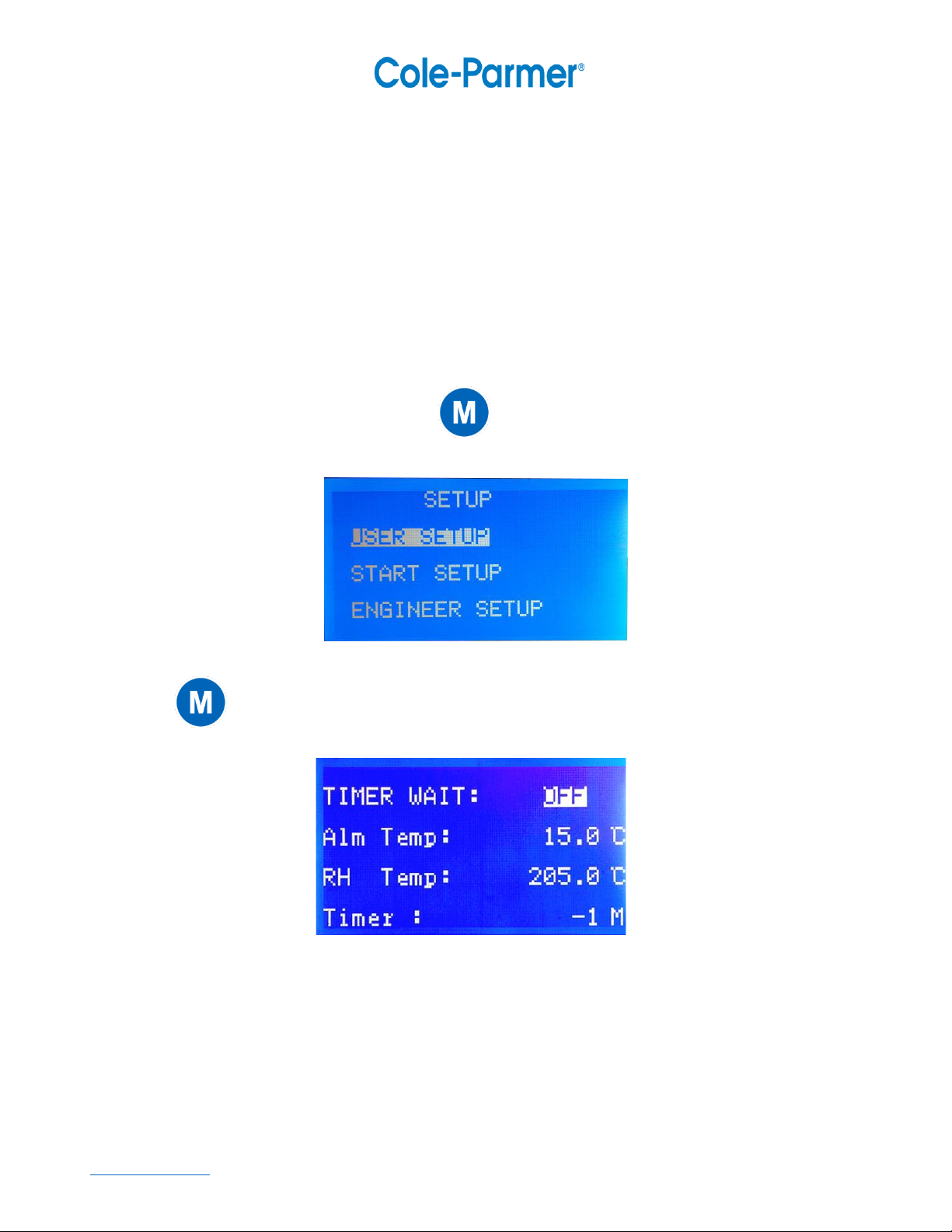
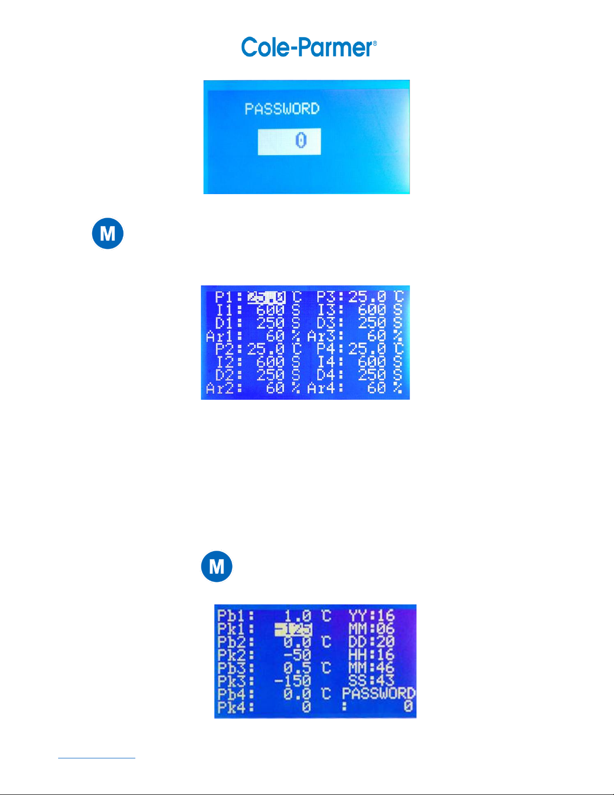
for optimal heat distribution. For detailed controller instructions, please see the next section.
g. To release vacuum upon completion, first power off the oven.
a. Rotate the Vacuum Release Valve to release your vacuum using atmospheric pressure. Or,
b. Connect an inert gas source to the Inert Gas Purge Port, and open the Inert Gas Purge
Valve to release your vacuum using an inert gas such as nitrogen.
h. When ambient pressure has been restored inside the oven, the door will open. You must wait
until pressure is completely restored, or a vacuum seal will hold the door closed.
a. Sometimes, it may be necessary to use your thumb or a flat screwdriver to separate a small
section of the Door Gasket from the glass window. A small “flick” will be enough to break
the seal- do not pierce the gasket! Please contact our support if you require assistance.
i. Take proper precaution when removing items from the oven as the contents will be hot!
5. Temperature Controller Detailed Operation
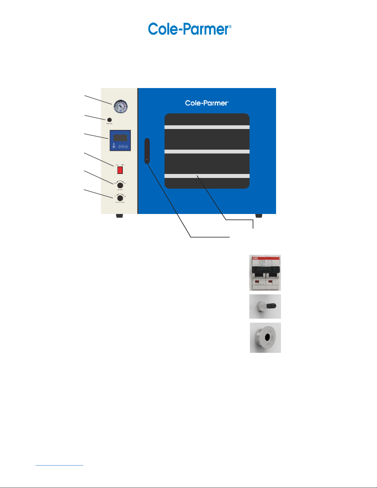
5.1 controller panel layout
①②③④

52411Vacuumoven_ver_1.0 as version
www.coleparmer.com
①Set button: used to set the target temperature value and enter the internal parameter layer.
②ESC return key: used to return when operating.
③Add key: used to move the cursor or change the value.
④Decrease button: used to move the cursor or haircut value.
5.2 Setting of experimental target value
5.2.1 Tap“ ” Set key, SET value backlit display in Figure 4.
5.2.2 With“ ” increase key or “ ” decrease key to change the value to the target value.
5.2.3 After the value becomes the target value,tap“ ”Set key,save the target value.
Note: Pressing the button once will only increase or decrease 0.1. by long pressing “ ” increase button
or“ ” drop button to change the value quickly.
Fig. 4
5.2.4 Figure 4 screen function introduction
F1: the first layer measures the temperature; F2: the second layer measures the temperature;

52411Vacuumoven_ver_1.0 as version
www.coleparmer.com
F3: third layer measures temperature; F4: fourth layer measures temperature;
(Note: When “==” is displayed, it means that the sensor is not connected.)
RUN/STOP: Operating status display.
8:16: Controller system time display.
SET: Set value display.
℉/℃: Temperature unit symbol display.
5.3 Alarm temperature value and timing function setting
5.3.1 In the standard screen (Figure 4), long press“ ” The setting button appears as shown in Figure 5.
Fig.5
5.3.2 Click the “ ” setting button again, and the screen shown in Figure 6 appears.
Fig. 6
5.3.3 Figure 6 screen function introduction
TIMER WAIT: Timing function standby temperature switch, there is standby temperature when ON, and no
when OFF. (Note: Standby temperature (default is 0.5°F/°C) refers to the temperature waiting for timing.
When the timing time is set and running, when the measured value differs from the set value by more than
0.5°F/°C, the timing time is not counted).
ALM Temp: Alarm temperature setting, that is when measuring temperature >SET+ALM TEMP, alarm。

52411Vacuumoven_ver_1.0 as version
www.coleparmer.com
RH Temp: Upper temperature control setting, the maximum value is 572 °F (300 °C).
Timer: Timing time when timing function. (Note: setting 0 to not count).
5.4 Start time setting .
5.4.1 In the standard screen (Figure 4), long press“ ” setting button appears as shown in Figure 5.
5.4.2 Click“ ”decrease key,Move the cursor to “START SETUP”,click“ ” setting button appears
in Figure 7.
Fig. 7
5.4.3 Figure 7 screen function introduction
START TIMER:Appointment start switch, ON enabled, OFF is not enabled.
YEAR MONTH; DAY HOUR
MINUTE
5.4.4 After setting the scheduled power-on time, set START TIMER to ON, that is, start standby, when the time
is up, start running.
5.5 PID parameter adjustment operation
5.5.1 In the standard screen (Figure 4), long press“ ” setting button appears as shown in Figure 5.
5.5.2 Click“ ”decrease key,Move the cursor to “ENGINEER SETUP”, click“ ” setting button
appears in Figure 8.

52411Vacuumoven_ver_1.0 as version
www.coleparmer.com
Fig. 8
5.5.3 Click“ ” Set key twice (since the password is set to 0, so double click into the parameter layer),
enter the parameter layer, as shown in Figure 9.
Fig.9
5.5.4 Figure 9 screen function introduction
P1: first layer P value; I1: first layer I value; D1: first layer D value; Ar1: first layer overshoot suppression
parameter. Other analogies. [Note: There is currently no PID automatic calculation function.
5.6 Calibration
5.6.1 In Figure 9,Keep pressing“ ”decrease key until the screen shown in Figure 10.
Fig. 10

52411Vacuumoven_ver_1.0 as version
www.coleparmer.com
5.6.2 Figure 10 screen function introduction
Pb1:First layer overall correction; Pk1: first layer linear correction; other analogy.
YY:Year;MM:Month;DD:Day;HH:Hour;MM:Minute;SS:Second;
(Here is the instrument system time setting)
PASSWORD:Password modification, directly enter a new password. (Note: Please remember to set the
password, if you forget, you will not be able to enter the parameter layer)
Linear correction formula:
PK={(Measured value H-measured value L)/(Set value H - set value L)-1}*4000
(Note: Due to the fact that the current instrument program is not perfect, the correction function is still
defective.)
5.7 Other operations 11
5.7.1 In Figure 9,keep click “ ”decrease key, until the picture shown in Figure 11.
Fig. 11
5.7.2 Figure 11 screen function introduction
T.Ch: Control layer selection, 1 only controls F1, 4 controls F1~F4;
Logo: LOGO switch, 0 is not displayed when the controller is started, 1 is displayed;
Unit: Temperature symbol selection, 0 is °C, 1 is °F.
5.8. Alarm / Faults
The oven has a built-in overtemperature protection circuit. If the oven’s temperature overshoots, the
controller will enter an Alarm Mode that disables all heating elements to protect your samples.
When in Alarm Mode, a red alarm indicator will display on the screen. The oven will automatically
resume operation when the temperature has dropped back below the overshoot threshold.
Setting the temperature setpoint higher will also resume heating function.
If your oven alarm is sounding due to an elapsed timer, press the Any key to mute!

52411Vacuumoven_ver_1.0 as version
www.coleparmer.com
6. Troubleshooting
Issue
Symptom
Cause
Solution
Unit does not switch on
No lights, no display
when switched on
Circuit breaker has
tripped
Reset breaker, located on oven
rear. See Fig. 4.
No temperature reading
Controller displays “----"
Loose electrical
connection
Check connections on circuit
board
Faulty probe
Replace probe. RTD 100Ω.
Oven does not heat
Oven remains at room
temperature
Temperature setting is
too low
See section 5.1. Temperature
Setting
Timer has expired
See section 5.2. Additional
Timer Information
Faulty controller. Check
controller for solid or
blinking Heat Indicator
icon (yellow). See Fig.5.
If temperature is correctly set
and still no Heat Indicator,
replace controller
Faulty heating relay
Check heating relay. LED on
relay will blink in sync with
controller Heat Indicator.
Replace if faulty.
Oven significantly
overheats
Oven constantly heating
Temperature set too high
See section 5.1. Temperature
Setting
Faulty heating relay
Replace if R < 1MΩ
Inaccurate temperature
reading
Controller readout does
not match real-world
temperature
Check preheat duration
Allow proper time for heat to
saturate oven internals
Check measurement
method
Releasing vacuum pressure will
temporarily cool oven due to
colder atmosphere
It is not recommended to use a
laser probe to check
temperature without
compensating for reflective
emissivity.
Use conventional thermometer
with direct physical contact to
shelf.
Perform probe calibration
See section 6.1. Calibration
Poor temperature
maintenance
Temperature regulation
does not meet ±1⁰
stability
Check environmental
operating conditions
Oven operational environment
must be from 0 - 30⁰C and <
30% RH
Perform automated PID-
tuning routine
**Must contact technical
support for detailed
instructions. Doing this
operation without contacting
technical support will VOID any
warranty.

52411Vacuumoven_ver_1.0 as version
www.coleparmer.com
Cannot initiate vacuum
Vacuum gauge needle
does not move, door can
open easily
Check vacuum connection
Be sure all pump and hose
fittings are secured
Ensure vacuum valve, purge
valve, and release dial are in
appropriate position
Check door seal
Remove and clean door gasket
with warm water to remove
potential dust or debris
Issue
Symptom
Cause
Solution
Cannot initiate vacuum
(continued)
Vacuum gauge needle
does not move, door can
open easily
The door is not closed
well
The door does not create
a complete seal between
gasket and glass
Loosen nut 3-5 turns
counterclockwise.
Tighten door pin 1 full turn
clockwise.
Using a wrench to maintain
upright position of door pin,
tighten nut clockwise with 2nd
wrench, locking door pin.
Repeat steps until door handle
firmly latches against pin.
Cannot pull full vacuum
Vacuum gauge cannot
reach desired pressure
Check elevation
Maximum vacuum level is
limited by operating elevation
Check elevation chart to
confirm maximum possible
vacuum
A pipe connection or
fitting is loose
Tighten and secure vacuum
connections

52411Vacuumoven_ver_1.0 as version
www.coleparmer.com
7. Packing List
Name
Quantity
User Manual
Included, 1
Vacuum Hose
φ16mm/Flare
Vacuum Pump Flare Fitting
KF25 centering ring and gasket, 1
KF25 clamp, 1
KF25 xφ16mm /Flare adapter, 1
8. Contact
United States –Cole-Parmer, 625 East Bunker Ct, Vernon Hills IL, 60061
T: 800-323-4340 E: sales@coleparmer.com W: coleparmer.com
EU –Antylia Scientific GmbH, Futtererstr. 16, 97877 Wertheim, Deutschland
UK –Antylia Scientific, 9 Orion Court, Abuscade Road, Colmworth Business Park, St Neots PE19 8YX
T: +44 (0) 1480 277339 E: uk.sales@antylia.com W: coleparmer.co.uk
Italy –T: +39 (0) 1313 895 13 E: it.sales@antylia.com W: coleparmer.com
Check release dial and purge
valve
The vacuum gauge is
damaged
Replace vacuum gauge
Oven vacuum leak
Vacuum loss of >1”Hg
within 24 hours
Door gasket is worn
Replace door gasket
Valves improperly closed
Check valve positions
A pipe connection or
fitting is loose
Tighten and secure vacuum
connections
Vacuum valve is leaking
Replace vacuum valve
This manual suits for next models
3
Table of contents
Other Cole Parmer Oven manuals
Popular Oven manuals by other brands

Infiniton
Infiniton HORNO B4VK Instructions for use - installation advice

Fisher & Paykel
Fisher & Paykel OB60SL Series installation instructions

Bosch
Bosch HBS573B.0B User manual and installation instructions

Grundig
Grundig GEBM11301XP user manual

Wolf
Wolf e Series Use and care guide

Buffalo
Buffalo DN486 instruction manual