Cole Parmer FHD-400 Series User manual

Cole-Parmer®
FHD-400 Series
Ductless Fume Hoods
USER OPERATION MANUAL
78902-20
78902-21
78902-22
78902-23
78902-24
78902-25
78902-26
78902-27

2 \ USER OPERATION MANUAL: FHD-400 Series
Cole
-
Parmer
® coleparmer.com
Table of Contents
Safety Warnings / Symbols .......................................................................................................................................... 3
Limitation of Liability ................................................................................................................................................... 3
Warranty ...................................................................................................................................................................... 4
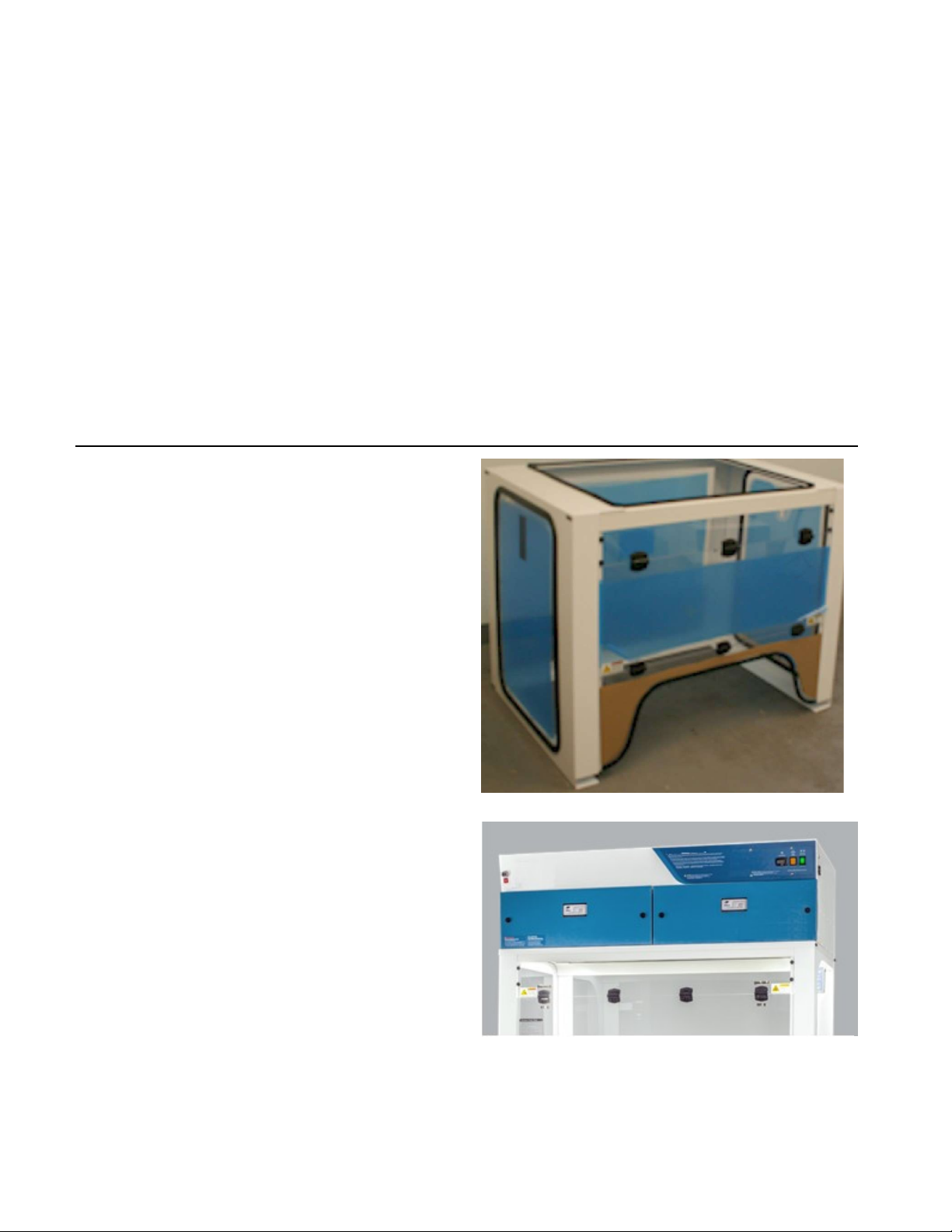
I. Product Information .................................................................................................................................... 5
II. Unpacking Your Cabinet ............................................................................................................................. 5
2 .1 Step-By-Step Procedure ......................................................................................................................................... 5
2 .2 Packaging Contents ............................................................................................................................................... 6
III. Installing Your Cabinet .............................................................................................................................. 7
3 .1 Choosing a Suitable Location ................................................................................................................................. 7
3 .2 Environmental / Electrical Conditions ..................................................................................................................... 7
3 .3 Installing Your Cabinet ........................................................................................................................................... 8
3 .4 Set Up .................................................................................................................................................................... 9
3.5 Performance Validation / Certification ....................................................................................................................... 15
3.6 Importance of Performance Validation / Certification ............................................................................................... 15
3 .7 Disclaimer ............................................................................................................................................................ 15
IV. Operating Your Cabinet ...........................................................................................................................16
4 .1 Control System .................................................................................................................................................... 16
4 .2 Cabinet Operating Procedure ................................................................................................................................ 17
V. Monitoring ............................................................................................................................................... 18
5 .1 General................................................................................................................................................................. 18
5 .2 Manual Monitoring ............................................................................................................................................... 18
VI. Maintenance ........................................................................................................................................... 19
6 .1 General ................................................................................................................................................................ 19
6 .2 General Cleaning .................................................................................................................................................. 19
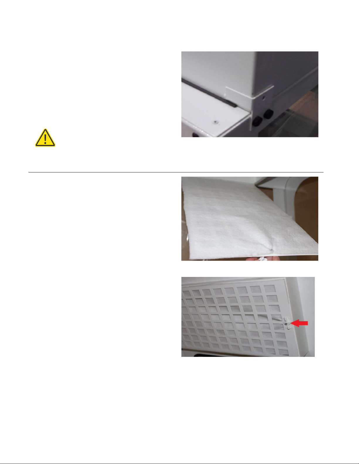
6 .3 Pre-Filters ............................................................................................................................................................ 19
6 .4 Lights ................................................................................................................................................................... 19
6.5 Airflow .......................................................................................................................................................................... 19
6 .6 Filter Condition Monitor (Fitted as an Option) ...................................................................................................... 20
6 .7 Calibration Instructions ........................................................................................................................................ 20
6 .8 Changing Out Filters ............................................................................................................................................ 21
6.9 Airflow Adjustment ..................................................................................................................................................... 21
6 .10 Maintenance Schedule ....................................................................................................................................... 22
6 .11 User Monthly Maintenance Schedule ................................................................................................................. 22
6 .12 Fault Finding ...................................................................................................................................................... 23
6 .13 Component Changing ......................................................................................................................................... 24
6 .14 Replacement Parts List ....................................................................................................................................... 24
VII. Filter Information ................................................................................................................................... 25
7 .1 Filter Descriptions ................................................................................................................................................. 25

3 \ USER OPERATION MANUAL: FHD-400 Series
Cole
-
Parmer
® coleparmer.com
Safety Warnings
• Read all instructions before proceeding and observe the installation procedure and
environmental/electrical requirements
.
• Anyone working with, on or around this equipment should read this manual
.
Failure to read,
understand and follow the instructions given in this documentation may result in damage to the
unit, injury to operating personnel and/or poor equipment performance
.
• Any internal adjustment, modification or maintenance to this equipment must be undertaken by
qualified service personnel.
• The use of any hazardous material in the cabinet must be monitored by an industrial hygienist, safety
officer or some other suitably qualified individual.
• Explosive or inflammable substances should never be used in the cabinet unless a qualified safety
professional has evaluated the risk involved
.
• If chemical, radiological or other non-microbiological hazards are being used in the cabinet, additional
protective measures should be taken
.
Additionally, the operation should be monitored by a suitably trained
individual
.
• If the equipment is used in a manner not specified by this manual, the protection provided by this
equipment may be impaired
.
• Even with the benefits they provide, germicidal ultraviolet lamps pose imminent danger if used without taking the
proper precautions
.
You MUST avoid exposure to direct or reflected germicidal ultraviolet rays, since they cause
painful eye irritation and reddening of the skin
.
In order to use our direct germicidal UVC products, you MUST wear
personal protection equipment—gloves, a long sleeve shirt with no gaps between cuffs and gloves and an
ultraviolet-blocking face shield to protect eyes and exposed skin
.
Under no circumstances should any direct
germicidal UVC unit be permitted to operate with humans, plants or animals present in the operation area
.
Symbols
Warning of hazardous area or situation
Limitation of Liability
The disposal and/or emission of substances used in connection with this cabinet may be governed by various local
regulations
.
Familiarization and compliance with any such regulations are the sole responsibility of the users of the
cabinet
.
The liability of Cole-Parmer® is limited with respect to user compliance with such regulations
.
European Directive on Waste Electrical and Electronic Equipment (WEEE)
At the end of your product / accessories life, it must not be discarded as domestic waste
.
Ref: EU
Directive 2012/19/EU on Waste Electrical and Electronic Equipment Directive (WEEE)
.
Please contact
your distributor / supplier for further information
.
For end users outside of the EU consult applicable
regulations
.

4 \ USER OPERATION MANUAL: FHD-400 Series
Cole
-
Parmer
® coleparmer.com
Warranty
The manufacturer agrees to correct for the original user of the product, either by repair (using new or refurbished parts),
or at the manufacturer’s election, by replacement (with a new or refurbished product), any defects in material or
workmanship which develop during the warranty period. The standard warranty is twelve (12) months after delivery of the
product for Non-Consumable and Electrical parts, excluding Filters and other Consumables. In the event of replacement,
the replacement unit will be warranted for the remainder of the original warranty period or ninety (90) days, whichever is
longer. For purposes of this limited warranty, “refurbished” means a product or part that has been returned to its original
specifications. In the event of a defect, these are your exclusive remedies.
If the product should require service, contact the manufacturer’s/supplier’s office for instructions. When return of the
product is necessary, a return authorization number is assigned and the product should be shipped, transportation
charges pre-paid, in either its original packaging or packaging affording an equal degree of protection to the indicated
service center. To ensure prompt handling, the return authorization number must be placed on the outside of the
package. A detailed explanation of the defect should be enclosed with the item. The warranty shall not apply if the defect
or malfunction was caused by accident, neglect, unreasonable use, improper service, acts of God, modification by any
party other than Cole-Parmer, or other causes not arising out of defects in material or workmanship.
EXCLUSION OF IMPLIED WARRANTIES. THERE ARE NO WARRANTIES, EXPRESSED OR IMPLIED, INCLUDING, BUT
NOT LIMITED TO, THOSE OF MERCHANTABILITY OR FITNESS FOR A PARTICULAR PURPOSE WHICH EXTEND
BEYOND THE DESCRIPTION AND PERIOD AS STATED IN THE OPERATOR’S MANUAL INCLUDED WITH EACH
PRODUCT. LIMITATION ON DAMAGES. THE MANUFACTURER’S SOLE OBLIGATION UNDER THE WARRANTY IS
LIMITED TO THE REPAIR OR REPLACEMENT OF A DEFECTIVE PRODUCT AND THE MANUFACTURER SHALL NOT, IN
ANY EVENT, BE LIABLE FOR ANY INCIDENTAL OR CONSEQUENTIAL DAMAGES OF ANY KIND RESULTING FROM USE
OR POSSESSION OF THIS PRODUCT.
Some states do not allow: (A) limitations on how long an implied warranty lasts; or (B) the exclusion or limitation of
incidental or consequential damages, so the above limitations or exclusions may not apply to you. This warranty gives you
specific legal rights and you may have other rights that vary from state to state.
Proposition 65
California Proposition 65: The California Safe Drinking Water and Toxic Enforcement Act of 1986
.
California voters have approved legislation that requires manufacturers to notify customers of "potential" health hazards
from specific chemicals, even those used in the production of sub-component parts manufactured by third parties. The
statute defines these hazards as cancer or reproductive harm.
Proposition 65 applies to any company doing business in California
.
Cole-Parmer has agreed to place labels on our
products to comply with the precepts of Proposition 65
.
WARNING
Use of this product can expose you to chemicals known to the State of California to cause cancer and birth defects or
other reproductive harm
.
For more information:
•
For exposures to listed carcinogens, Cancer, www.P65Warnings.ca.gov
.
For exposures to listed reproductive toxicants, Reproductive Harm, www.P65Warnings.ca.gov
.
For exposures to both listed carcinogens and reproductive toxicants, Cancer and Reproductive Harm,
www.P65Warnings.ca.gov
.

5 \ USER OPERATION MANUAL: FHD-400 Series
Cole
-
Parmer
® coleparmer.com
I
.
Product Information
The FHD-400 Advanced Series ductless fume hoods are a series of high efficiency products designed to protect the user
and the environment from hazardous vapors generated on the work surface
.
At the heart of the fume hood product line is
the innovative Cole-Parmer Filtration Technology that creates a safe work environment over the widest range of
applications in the industry
.
Visit our website for FHD-400 Advanced Series ductless fume hood specifications.
II
.
Unpacking Your Cabinet
This chapter aims to provide relevant information on how to handle the cabinet properly upon receipt
.
Failure to follow
these instructions may damage the cabinet
.
We strongly advise you to read this chapter carefully before proceeding
further
.
2 .1 Step-By-Step Procedure
1
.
Inspecting the Crate, Pallet, Boxes
.
» Upon receipt of your new cabinet, inspect all cartons
.
If there is any visible damage to the exterior please call Cole-
Parmer.
2
.
Moving the Pallet
.
» The pallet is designed to protect the cabinet from any foreseeable circumstances
.
However, excessive impact on
the boxes or pallet may also damage the cabinet
.
Prevent any direct impact or hitting to the pallet when
moving
.
» When lifting the pallet, always ensure that the floor jack or mechanical lift truck has fully entered under the pallet
in order to achieve stability
.
Failure to do so will increase the risk of the pallet falling off the floor jack or mechanical
lift truck during handling. Please use a suitable extension bar when necessary.
3
.
Opening the Boxes
.
» If you did not receive one or more of the parts listed on the packing checklist, or if any of the items are damaged,
please call Cole-Parmer.
4
.
Removing the Packaging Material
.
»
The cabinet is protected by foam, cardboard and/or shrink-wrap
.
» If you find any damage during this stage of unpacking, please call Cole-Parmer.
» We recommend leaving the cabinet secured with straps to the pallet until the cabinet is located in its
approximate final position to facilitate ease and safety in handling.
NOTE: Choosing the best location for your cabinet in order to achieve optimum operating performance is
determined by a number of factors. Please refer to the next chapter for guidelines.

6 \ USER OPERATION MANUAL: FHD-400 Series
Cole
-
Parmer
® coleparmer.com
5
.
Moving the Cabinet
.
» When lifting the pallet with the cabinet, always ensure that the floor jack or mechanical lift truck has fully entered
under the pallet
.
This is to increase the stability of the cabinet and reduce the risk of the cabinet
falling down
.
Please
use a suitable extension bar when necessary
.
During
the
moving
of
the
cabinet,
ensure there is enough distance
between the supports of the pallet and the ground
.
Dragging the pallet against the ground will damage the pallet
and possibly your new cabinet
.
» When removing cabinet from pallet or placing cabinet onto pallet, use at least two people
.
6
.
Removing the Strapping
.
» Remove the strapping by cutting it at a safe position to prevent scratching the surface of your new
cabinet
.
» Do not discard the packaging material for your cabinet until you have checked all of the components, installed
and tested the unit
.
7
.
Lifting the Cabinet
.
» The cabinet can be lifted in two sections: The HEAD unit and ENCLOSURE
.
» Install the cabinet on the existing work surface or Cole-Parmer support stand (if ordered)
.
NOTE:
» When installing the cabinet onto an existing work surface, ensure that the structure can safely support the
combined weight of the cabinet and any related equipment. Some modifications to the work surface may be
necessary
.
» The work surface should be smooth, non-porous and resistant to the disinfectants and chemicals used in
conjunction with the cabinet
.
2 .2 Packaging Contents
The following items are included with your manual:
• Test Report
In case this manual and/or test report is lost or misplaced, Cole-Parmer retains a copy in our files. A replacement copy
can be obtained by contacting Cole-Parmer and providing the cabinet model, serial number and a brief description of
the information desired.

7 \ USER OPERATION MANUAL: FHD-400 Series
Cole
-
Parmer
® coleparmer.com
III
.
Installing Your Cabinet
3 .1 Choosing a Suitable Location
Location impacts the nature and extent of external airflow disturbances, which may affect performance of the
cabinet when it is exposed to these disturbances
.
When installing the cabinet, it should be located as far away as possible from sources of airflow disturbance and in an
orientation which optimally shields the airflow of the cabinet from all external airflow disturbances. Please note that the
cabinet should not be placed close to another cabinet
.
Please follow these guidelines when choosing a suitable location for your cabinet.
• The location must be far away from:
» Personnel traffic flows.
»
Air vents (in and out).
»
Doors and windows.
»
Any other sources of disruptive air currents or air drafts.
• If drafts or other disruptive air currents exceed the face velocity of the filter, the potential exists for
contaminated air to enter the work zone of the cabinet.
• A minimum distance of 50 cm (20 in) to the top of the ceiling is recommended for blower changing purposes
.
• A clearance of 183 cm (6 ft) in front of the cabinet is strongly advised in order to maintain proper airflow.
• Please permit adequate space for cleaning behind the cabinet
.
3 .2 Environmental / Electrical Conditions
The equipment is designed to be safe for at least the following conditions:
»
Indoor use
.
»
Altitude < 2,000 m (6,562 ft)
.
»
Temperature range 5ºC to 40ºC (41ºF to 104ºF) ambient
.
»
Relative humidity <80% up to 31ºC (88ºF) decreasing to <50% at 40ºC (104ºF)
.
»
UL Installation Category II
.
»
UL Pollution Degree 2
.
»
Continuous operation
.
»
Electrical supply tolerance of –10% / +10%
.
»
120VAC, 60Hz, 10A or 230VAC, 50Hz, 5A
.
» Fuse: 250V, 10A, Time Lag for 120VAC or Fuse: 250V, 5A, Time Lag for 230VAC
.
» Always ensure unit is connected to a reliable and properly grounded receptacle
.
» Appliance inlet on this device is disconnect device; appliance should not be positioned so that it is difficult to
operate it.

8 \ USER OPERATION MANUAL: FHD-400 Series
Cole
-
Parmer
® coleparmer.com
Power Cord:
1) For units intended to be operated at 120 volts (North America): Use a UL-listed and CSA-certified cord set
consisting of a minimum 18 AWG, Type SVT or SJT, three-conductor cord, a maximum of 15 feet in length and a
parallel blade, grounding-type attachment plug rated 15 amperes, 125 volts
.
2) For units intended to be operated at 230 volts: Use a cord set with a grounding-type attachment plug
.
The cord set
should have the appropriate safety approvals for the country in which the equipment will be installed
.
3 .3 Installing Your Cabinet
1
.
Please refer to unpacking your cabinet.
2.
Inspect your cabinet carefully. Should you find any defect please refer to the warranty.
Peel off any protective
masking that was left on the cabinet during manufacturing.
4
.
Wipe down the interior and exterior of the cabinet with water or a mild household detergent
.
5
.
Connect cabinet to the main power supply and turn on the blower
.
Each cabinet requires its own dedicated 13A (230V) or
15A (115V) power outlet which should not be shared with other appliances
.
WARNING! Do not move the cabinet without observing the following precautions:
•
Observe the necessary precautions when relocating the cabinet, as it is heavy
.
•
Warning - Tipping Hazard
.
Pushing high up on the unit may cause system to tip over
.
Be careful when
moving
.
Move with assistance only
.

9 \ USER OPERATION MANUAL: FHD-400 Series
Cole
-
Parmer
® coleparmer.com
3 .4 Set Up
Your Cole-Parmer product is shipped in two parts
.
The following instructions and photos explain how to:
Assemble the base “enclosure” and place the head unit (fan and controls) on top:
• Fit the main filter and the pre-filter.
• Fit the optional airflow meter.
• Adjust the fan speed/airflow control.
• Adjust the filter blockage alarm.
Prior to beginning assembly, ensure the following:
1
.
Area is free of obstructions, tripping hazards, etc
.
2
.
Ample clearance is available on sides and over head
.
3
.
Appropriate number of personnel are on hand: two people recommended
.
Fume Hood Assembly
1
.
Unpack fume hood enclosure and set on
top of casework
.
In most cases the enclosure
is shipped fully assembled. If unit is flat packed,
please follow “flat-packed enclosure
assembly sheet”
.
2. Unpack fan/filter module (aka head unit). Lift
head unit above and onto enclosure, allowing
airflow sensor/wire harness to hang
inside the
enclosure
.

10 \ USER OPERATION MANUAL: FHD-400 Series
Cole
-
Parmer
® coleparmer.com
3
.
Ensure head unit is properly aligned
.
Back
corners
of head unit should be touching the
guide
brackets on the top of the enclosure
.
Remove
protective film from clear panels.
Please allow a minimum clearance of 150 mm
(6 inches) between the right hand side of the unit and
any adjacent wall to allow the detachable power
supply cord to be disconnected from the power
source
.
Warning – Tipping Hazard. Please ensure that all end
rails of unit are completely on workbench and do not
overhang
the
workbench
in
any
location.
Filter Installation
4. Locate white pre-filter cloth and metal pre-filter tray.
Lay pre-filter on the tray with raised edges pointed
upward
.
5. Open the sash and lift pre-filter tray into the
inlet
cutout
.
Rotate the wing nuts on each side to
support the tray
.

11 \ USER OPERATION MANUAL: FHD-400 Series
Cole
-
Parmer
® coleparmer.com
6. To install the main filter(s), use key to unlock the
cam locks on filter door.
7
.
Place the wheels of the main carbon/HEPA
filter
on the track and push all the way in. If unit has
separate HEPA and carbon filters, stack the
carbon filter on top of the HEPA filter and
install.
8. Once in place, turn handles to secure filter.
9
.
Re-install door and lock cam locks using
filter
door key. The dimples on the locks
should
be aligned
.

12 \ USER OPERATION MANUAL: FHD-400 Series
Cole
-
Parmer
® coleparmer.com
Final Assembly
10. To install the airflow sensor, remove
the clear panel on the inner right sidewall
.
Open
the screw cap on the outside of the enclosure,
undo the screw and nut and set
aside
.
DO NOT
DISCARD!
11. Remove any tape on the airflow sensor which
is
used to protect the sensor wires
.
Install the
sensor
by attaching to the enclosure with the screw and
nut
.
12
.
If
not
already
installed,
slide
polypropylene spill
tray into the enclosure
.
The side with the
extended
handle/lip should go toward the back of the hood
.
Warning - Once installed do not remove spill tray
from enclosure. Do not use tray like a drawer. Do not
push down, lean on or apply excessive force. Tray is
only intended to sit over existing work surface.
13
.
Attach power cord to the inlet on the
right
side of the head unit and connect
to
appropriate power source
.

13 \ USER OPERATION MANUAL: FHD-400 Series
Cole
-
Parmer
® coleparmer.com
Air Velocity Meter Equipped Units
14. Add airflow meter as follows:
» Insert vane/film into the airflow meter.
a .
Slide out vane holder from side of meter
(just below the screw)
.
b
.
Carefully remove vane from plastic bag
and
cardboard envelope (two vanes are
enclosed, one is a spare)
.
Hang the vane
by
the wire in the two slots provided in
the vane
holder
.
c .
Slide the vane holder back into the meter
.
» The enclosure design allows the airflow meter
to be fitted to either side of the
enclosure as
required
.
Ensure that the side not to be used has the airflow
opening covered by the
supplied
blanking
plate
.
The side
to be used should have an open hole to fit the meter
.
»
Remove the attaching screw from the meter
.
» Push the screw into the screw hole from
the
outside of the enclosure
.
» Align the meter to the screw from the
inside of
the enclosure
.
» Tighten the screw to secure the meter in
place
.
NOTE:
The meter is now ready to take readings
.
It is pre-calibrated
.
If the vane becomes damaged, it is
easily replaced with the spare vane
.
The
vaneometer is
accurate to ± 5% of full scale from
0-100 fpm and ± 10%
from 100 fpm to 400 fpm
.
The permanent mounting bracket provided in
the
box is not used
.

14 \ USER OPERATION MANUAL: FHD-400 Series
Cole
-
Parmer
® coleparmer.com
15
.
Removable yellow caps are provided
in
the
rear
wall of the enclosure to allow cables and hoses to
be fed inside of the enclosure as required; refit the
yellow caps when the holes are not in use
.
16. To calibrate the filter blockage alarm (see
Calibration), use a small Phillips screwdriver to
adjust the screw inside the
calibration port
.
NOTE:
Adjustment
screw
is made of nylon, so
please use care not to
damage the screw
.

15 \ USER OPERATION MANUAL: FHD-400 Series
Cole
-
Parmer
® coleparmer.com
3.5 Performance Validation / Certification
After installation and prior to use, cabinet performance must be validated and certified to factory standards. The
following test should be performed:
Airflow Velocity
The testing methods and equipment required are specified on the test report. It is recommended that these tests be
performed only by a qualified technician who is familiar with the methods and procedures for certifying these types of
cabinets
.
3.6 Importance of Performance Validation / Certification
An airflow velocity value that falls below the value specified inside the test report will not provide adequate operator
protection
.
3 .7 Disclaimer
The performance of the cabinet, while rigorously evaluated at the factory, cannot be guaranteed after transit and
installation
.
Therefore on-site testing is always recommended
.

16 \ USER OPERATION MANUAL: FHD-400 Series
Cole
-
Parmer
® coleparmer.com
IV
.
Operating Your Cabinet
4 .1 Control System
Control Panel
The controller displays the airflow and offers limited detection of low concentrations of hydrocarbon, some gases and
organic acids. Audio and visual alarms alert users to filter saturation and if the airflow reaches preset thresholds. An Hour
Counter with preset alarm intervals for pre-filter and main filter change out is also included
.
Calibration Procedure
1 .
Power up unit
.
2
.
To set nominal run point, press and hold the mute key for 4 seconds; when an audio beep is
observed, release the mute switch
.
3
.
Using a calibrated anemometer, set the airflow to the desired velocity.
4
.
Using the up and down arrows, set the display to read that reading
.
5
.
Press the mute switch once to store calibration point
.
6
.
To set an alarm point, press and hold the mute switch then press and hold the up arrow key for 4
seconds; after audio beep release both switches
.
7 .
Set the display using the up and down arrows to the desired alarm point, in 0 .05 m/s increments
.
8
.
Press the mute switch once to store the alarm point
.
9 .
To display in FPM remove LK1, to display in m/s fit LK1.
CONNECTIONS PL2
PL2 ANEMOMETER PIN 1 RED
PL1 POWER PIN 2 BLUE
PL3 VOLTFREE CONTACT PIN 3 YELLOW
PL3 PINS 1 & 2 N/O
CLOSED ON ALARM

17 \ USER OPERATION MANUAL: FHD-400 Series
Cole
-
Parmer
® coleparmer.com
4 .2 Cabinet Operating Procedure
• The fume hood should only be operated with the correct filter installed for the application. Refer to Filter
Information for further information. The ductless fume cabinet must not be used for laboratory work in
which chemicals of different types are used that do not match the filter type or that the primary chemicals or their
byproducts are not known
.
The ductless fume cabinet should not be used for different chemical processes where
chemicals from the different processes could react in the filter.
• To start the system, apply power to the system and switch on the green power On/Off switch
.
The lights will
automatically switch on as will the fan
.
• Check the airflow and the filter condition of the cabinet on a regular basis. This is covered in Maintenance.
• Please note, filter blocks do not absorb carbon monoxide or hydrogen. Small quantities will not cause hazards
because of the large dilution factor from the amount of air passing through the cabinet and the retardation of
the chemical in the filter matrix.
• Cole-Parmer fume hoods have been designed to handle fumes and vapors given off during everyday laboratory
procedures. These will be at the parts per million (PPM) level in the air stream entering the filter block. It is not
recommended that large quantities of solvents or acids be used or boiled off in the cabinet
.
• In the event of a large spillage in the cabinet, the level of fumes entering the filter block may temporarily reduce
the efficiency of the filter. For this reason any major spillage must be cleared up immediately, preferably using
spillage absorption granules rather than paper, which may aggravate the evaporation of toxic fumes from the
spillage area
.
• Following a major spillage, the filters must be changed as the heat of wetting may reduce the efficiency of the
filter. After a period of stabilization, the old filters may be reused, providing they have not reached the saturation
level
.
• Ensure the electrical equipment in the cabinet such as the lights and controls are not in the dirty air stream of the
system. The system should not be used in a flammable room atmosphere. Special modified cabinets
can be
provided for use in these areas
.
Contact Cole-Parmer for further information on these applications
.
• Operators should avoid sudden movements within the fume cabinet, such as rapid opening or closing of the
sash window, as this may cause temporary reversal of the airflow.
• Operators should maintain the normal safety equipment and procedures for dealing with
hazardous chemicals
.
WARNINGS!
» Do not use a gas flame (Bunsen burner) whenever possible, as it interferes with airflow.
» Do not change original blower speed of the cabinet unless the change is required by a decrease in measured
air velocity. Adjustment should be made only by a qualified technician. Do not operate the cabinet if fan fails
to run
.
» Minimize arm movement. Move arms in and out of the cabinet slowly to avoid disrupting cabinet airflow.
» Use absorbent pads on the work surface where appropriate to minimize splatter and aerosol generation in case of
spillage
.
»
Keep lids/covers on all containers, dishes and sample plates.

18 \ USER OPERATION MANUAL: FHD-400 Series
Cole
-
Parmer
® coleparmer.com
V
.
Monitoring
5 .1 General
The purpose of the monitoring program is to ensure consistent reliability from the system
.
This is achieved by
checking the following:
• If the pre-filters become blocked, the velocity of the cabinet will begin to fall and will eventually cause the
airflow alarm to illuminate.
• Manual checking of the main filters by the use of a Gastec™ or Draeger™ test kit will confirm the condition of the
filters.
5 .2 Manual Monitoring
Manual monitoring of the cabinet should be carried out at least once per year, as this will ensure the monitoring systems
are all within calibration and performing correctly.
Airflow Measurements
The inflow velocity of the hood should be checked with the sash at the correct operating height using an anemometer
such as a hot wire, vane anemometer or propeller type
.
Depending on the size of the cabinet, a series of readings are to
be taken at the front opening; these are to be recorded on a service sheet or system log sheet
.
Manual Filter Testing
The condition of the filter is to be checked using a Gastec or Draeger test kit. Boiling off a suitable chemical normally
used in the cabinet or a controlled release should challenge the filter. Examples can include alcohols, toluene and
trichloroethylene
.
For testing acid filters (acid adsorbing) or multi combination layered filters incorporating an acid layer, use sulphur
dioxide gas (SO2) at 2 bubbles per second through water
.
The readings should be below your Country’s Occupational Exposure Limit. The results are to be recorded on a
service sheet or system log sheet
.
If a significant amount of chemical is noted at the exhaust of the system, the main filters should be changed.

19 \ USER OPERATION MANUAL: FHD-400 Series
Cole
-
Parmer
® coleparmer.com
VI
.
Maintenance
6 .1 General
In some countries it is mandatory to maintain written records of checks, tests and repairs carried out on safety
equipment
.
These records must be kept for 5 years
.
A full list of Occupational Exposure Limits should be obtained from
your safety officer.
Regular preventative maintenance on the cabinet will reduce the possibility of hazard to the operator and ensure
reliable performance from the cabinet
.
WARNING! Before attempting inspection and repairs to the cabinet, please ensure main power to the
system has been disconnected and that the power lead has been removed. It should also be noted that
fume cabinets are sometimes used to contain and protect users of the cabinet from hazardous or harmful
substances. Before commencing this schedule it is important to ensure the cabinet is safe to work on.
6 .2 General Cleaning
Wipe down the unit with only soapy water.
6 .3 Pre-Filters
Check condition and replace if required.
6 .4 Lights
Ensure that the light diffuser is clean before switching the system on
.
Check that the light is in working condition.
6.5 Airflow
Check and record the inflow air velocity at the working aperture as follows: Using a calibrated hot wire or vane
anemometer or similar approved airflow meter, take a minimum of 5 readings across the fume cabinet aperture as shown
below. Calculate the average airflow, which should be greater than 0.5 m/sec or 100 fpm +/- 10%.
The readings should be recorded on the service sheet or system log
.

20 \ USER OPERATION MANUAL: FHD-400 Series
Cole
-
Parmer
® coleparmer.com
6 .6 Filter Condition Monitor (Fitted as an Option)
Under normal operating conditions (if option fitted) the display will show a green filter to indicate it is safe. If the filter
display is red, the filter should be checked as follows:
• Select a suitable test chemical (examples include alcohols, toluene, trichloroethylene or any suitable chemical
in routine use in the cabinet providing it is well adsorbed and not dangerously toxic) and a matching Gastec or
Draeger test kit
.
• Place 6 ml of the chemical into a beaker on a hot plate inside the cabinet
.
Set the hot plate to boil off the chemical
over a 2 minute period
.
This should give a concentration of about 100 - 200 PPM (parts per million) challenge to
the filter.
• If testing acid filters (acid adsorbing) or multi combination layered filters incorporating an adsorbing layer, use
sulphur dioxide gas (SO2) at 2 bubbles per second released through water to challenge the filter.
• Using the test kit, take a sample reading at the outlet of the cabinet
.
Follow the instructions supplied with the tubes;
i .e
.
the number of strokes for each type of tube
.
• If a significant level of chemical is recorded at the outlet, the filter must be changed. It is also worth checking
the gasket condition for any damage that may result in a bypass
.
6 .7 Calibration Instructions
Testing the Filter Blockage Alarm
• Ensure the fitted pre-filters are new. Switch on the cabinet; the red/amber neon should not be illuminated.
• Switch the unit off. Block the pre-filter using paper or cardboard to permit airflow of <0.3 m/sec or 60 fpm.
•
Switch the unit on
.
The red/amber neon should illuminate
.
If not, the calibration will need to be reset
.
Calibration
The filter blockage alarm operates using a differential pressure switch to detect a “high vacuum” situation when the pre-
filter is blocked or blocking up. The pressure switch is calibrated and tested prior to leaving our factory and under normal
circumstances will not require any adjustment
.
• With the cabinet running and the pre-filter blocked as described above, locate the grey pressure switch through the
hole in the right hand sidewall
.
Adjustment is made by turning the small screw in the end of the switch
.
• Adjust the screw to make the alarm show
.
You may have to repeat these steps to ensure an accurate setting has been
achieved
.
•
Remove the blockage and restart the machine
.
The red/amber neon should not be illuminated
.
This manual suits for next models
8
Table of contents
Other Cole Parmer Ventilation Hood manuals
Popular Ventilation Hood manuals by other brands

Electrolux
Electrolux EFF55550DX user manual

Bosch
Bosch DID106T50 instruction manual

Kuppersbusch
Kuppersbusch KD 9660.0GE Instructions for use and installation instructions

Whirlpool
Whirlpool UXT3030AY Installation Instructions and Use & Care Guide

Candy
Candy CIDC 61/1 X Installation and user manual

Fisher & Paykel
Fisher & Paykel HS60LXW4 Quick reference guide