INSTALLATION TROUBLESHOOTING
Page 7
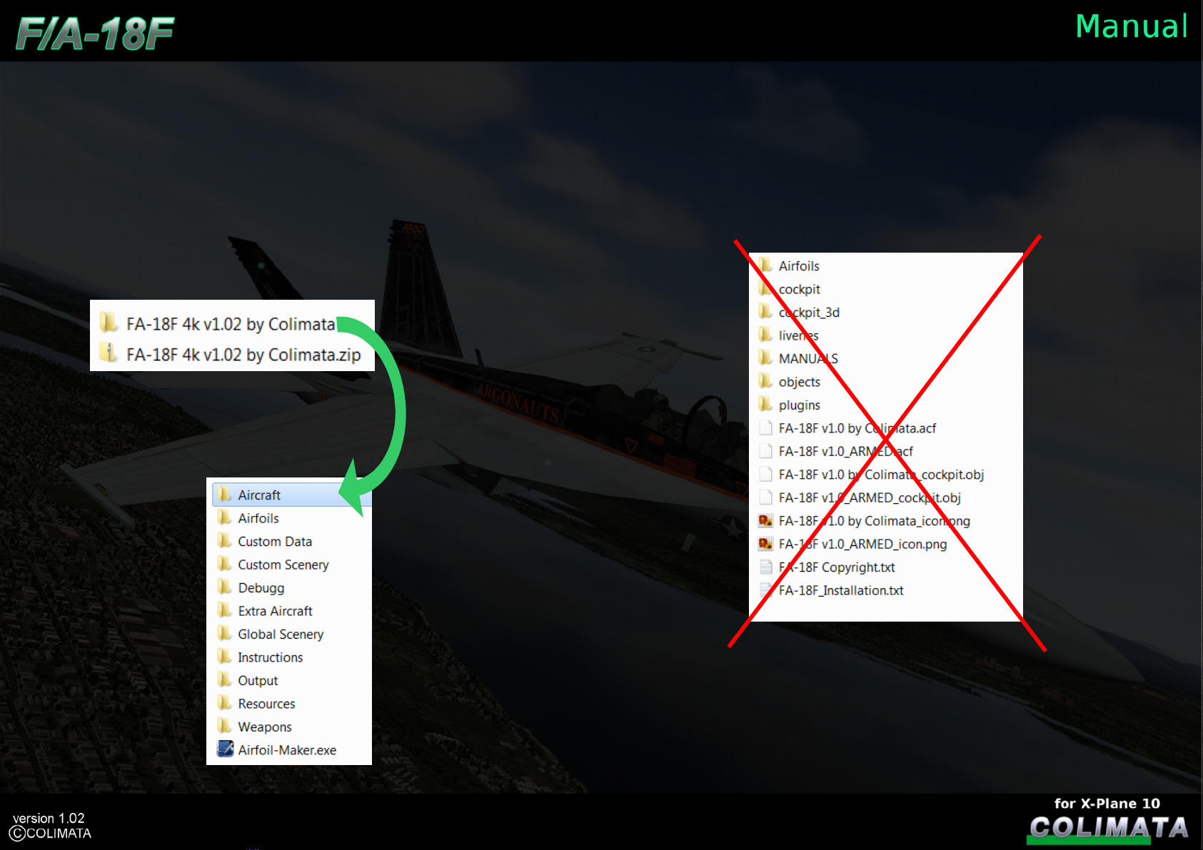
. Rename/Subfolder
Do not rename or move the A-18 main folder in another sub folder.
This could cause problems to the aircraft plugin due to a too long file path.
2. Administrator rights
Make sure that the main X-Plane folder is NOT located in a system path that needs administrator rights (like C:\Programs\).
The plugin could fail to start due to missing administrator rights.
3. Antivirus software
Assure that your antivirus software does not block the plugin, located in:
...\X-Plane 10\Aircraft\ A-18 4k v1.02 by Colimata\plugins\ A-18 plugins\64\” (32 for 32bit systems)
The software “lives” only inside X-Plane. No harm for your computer.
4. Microsoft libraries
or unknown reasons, some computers, even new ones, miss some Microsoft libraries. If you check the X-Plane LOG.txt file (in the main X-
Plane folder), and there's an “Error code = 126” near the A-18 plugin, then it is very likely that missing Microsoft libraries are the cause.
Many, also big office, CAD an other payware programs outside the X-Plane world need those libraries. It's good to have them on board.
Installation is done pretty quickly and represent no harm or heavy lifting for your computer.
The libraries are called “Microsoft Visual C++ Runtime libraries”. There are various versions of them. One series is called x86 for the old 32bit
systems and one series is called x64 for the 64bit systems (todays standard): v 2005, 2008, 2012, 2013, 2015.
Normally only version 2012 is needed. Here's the link:
https://www.microsoft.com/en-us/download/details.aspx?id=30679
There where however customers who needed to install the whole series from 2005 to 2015 to get it to run.
On the “issue solutions” thread, inside the x-plane.org forum, point 8 contains all the links to all the versions of the 64bit series.
Normally the aircraft runs “out of the box”. Should you nevertheless encounter a problem here's a list of possible causes. If there are
issues on the A-18 , they are mostly related to the so called “plugin”. This is a custom piece of software that powers the custom made HUD, the
Displays, some switches, the dynamic landing gear damping, etc.
ISSUE SOLUTIONS THREAD:
In the forum on x-plane.org I created an “issue solutions thread” that contains an updated list of issues and there solutions.
x-plane.org → Payware support → Designers → COLIMATA → A-18 Super Hornet
Here's the link: http://forums.x-plane.org/index.php?/forums/topic/95128-issue-solutions/