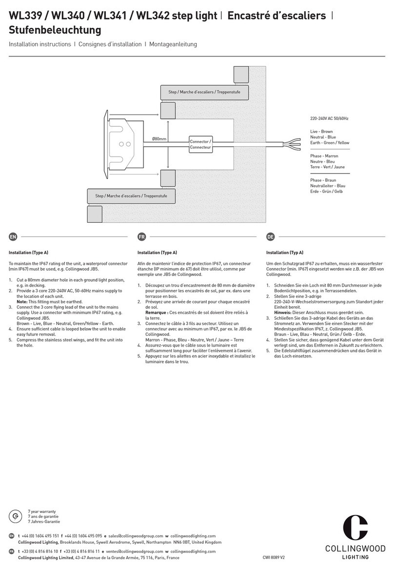
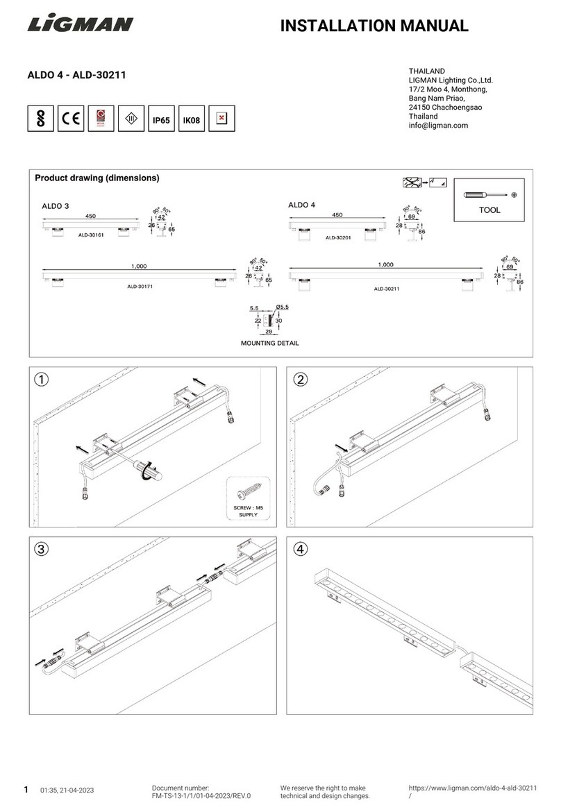
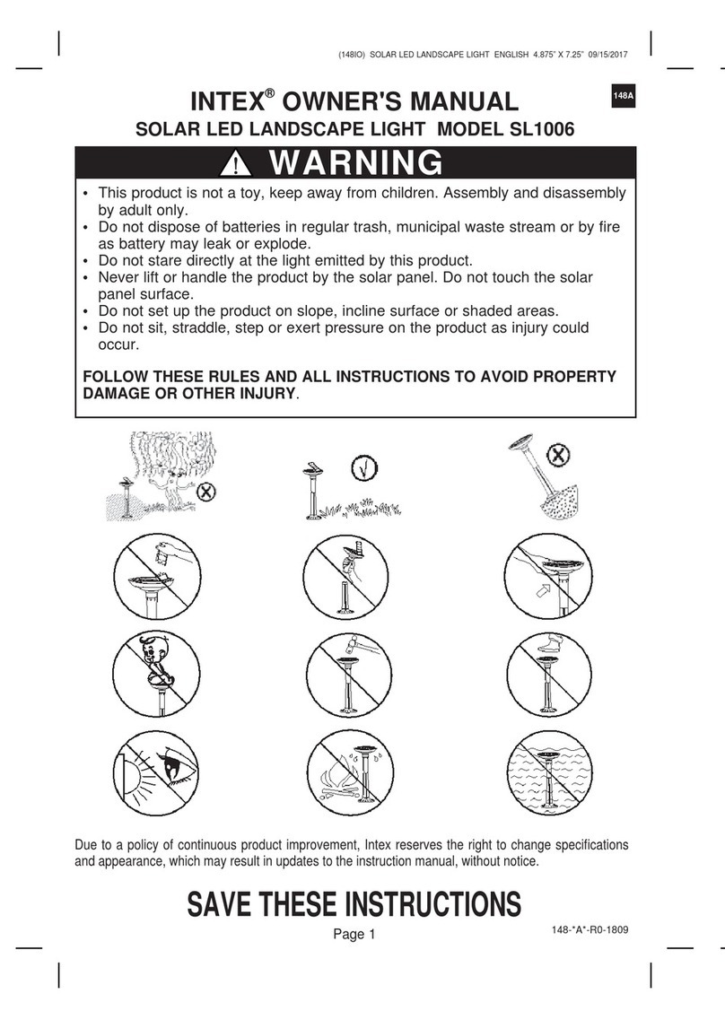
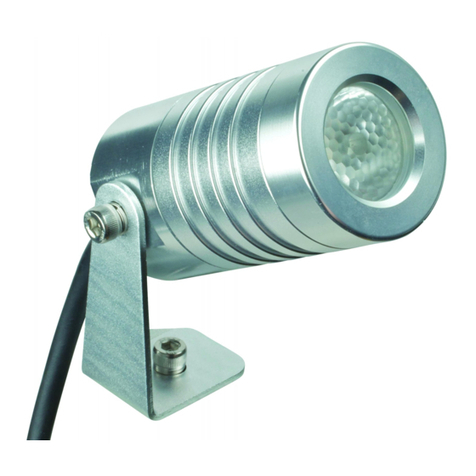
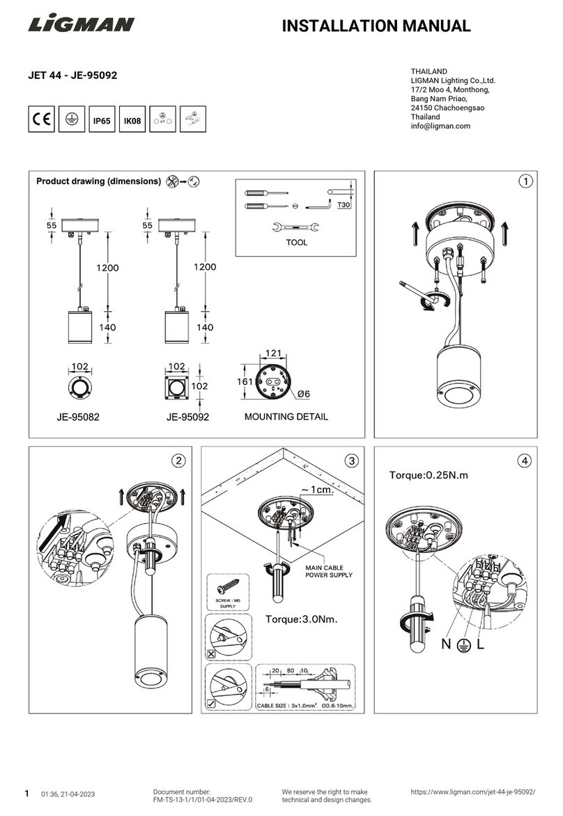
Collingwood Lighting GL07 User manual

GL07 / GL08 / GL09
INSTALLATION INSTRUCTIONS / CONSIGNES D’INSTALLATION / MONTAGEANLEITUNG
CWI 8113 V1
4. Using a Collingwood JB5 connector (or other suitable IP rated
connector), connect the ground light to the mains supply.
5. Fit the ground light into the installation tube, and rotate until it locates
in the square recesses (Fig 3).
6. See overleaf for installation data and beam angle adjustment.
4. En utilisant un connecteur JB5 (ou un connecteur étanche
approprié),connectez chaque encastré de sol au secteur.
5. Installez l’encastré de sol dans le tube d’installation et tournez pour
qu’il se bloque dans les renfoncements carrés (Fig 3).
6. Voir au verso pour les données d’installation et l’orientation du
faisceau.
4. Mit Benutzung eines JB5 Verbinders (oder eines IP geschützten
Verbinders) verbinden Sie den Bodeneinbaustrahler an das Stromnetz.
5. Stecken Sie den Bodeneinbaustrahler in die Hülse ein und drehen Sie
ihn bis er in die quadratischen Vertiefungen passt.
6. Für Installationsdaten und Abstrahlwinkel-Einstellung lesen Sie die
andere Seite.
This unit must be wired by a qualified electrician or suitable competent
person.
1. Provide a 3 core mains supply to each ground light position.
Note: These ground lights must be earthed.
2. Locate the installation tube as appropriate.
Fig 1 - shows a typical concrete installation
Fig 2 - shows a typical soil / gravel installation
Fig 3 - To ensure consistent light output, install all tubes with square
recesses pointing in the same direction as the required beam aim.
3. Installation advice is for guidance. All installations must comply with
the appropriate standards.
Ce produit doit etre raccordé par un électricien qualifié
ou une personne compétente appropriee.
1. Prévoyez une arrivée de courant pour chaque encastré de sol.
Note: Ces encastrés de sol doivent être reliés à la terre.
2. Mettez en place les tubes d’installation de façon appropriée.
Fig 1 - Schéma d’installation dans du béton.
Fig 2 - Schéma d’installation dans de la terre/ des graviers.
Fig 3 - Pour obtenir un flux lumineux homogène, installez tous les
tubes de façon à ce que les renfoncements carrés soient dirigés dans
la même direction que le faisceau.
3. Les conseils d’installation sont pour indication seulement. Toute
installation doit se conformer aux réglementations appropriées.
Dieser Strahler darf nur von einer Elektrofachkraft oder einer
entsprechend qualifizierten Person angeschlossen werden.
1. Stellen Sie für jeden Bodeneinbaustrahler eine Netzversorgung
(mit 3 Adern) her.
Achtung: diese Bodeneinbaustrahler müssen geerdet werden.
2. Platzieren Sie die Einbauhülsen wie vorgesehen.
Fig 1 - zeigt die Installation in Beton
Fig 2 - zeigt die Installation in Erde / Kies
Fig 3 - Um den gleichmäßigen Lichtaustritt zu sichern, platzieren Sie
alle Einbauhülsen mit quadratischen Vertiefungen, die in die gleiche
Richtung zeigen wie das gewünschte Anstrahlziel.
3. Die Montageanleitung dient nur als Orientierungshilfe. Bei allen
Installationen sind die angemessenen Sicherheitsnormen einzuhalten.
EN FR DE
Collingwood Lighting, Brooklands House, Sywell Aerodrome, Sywell, Northampton NN6 0BT, United Kingdom
t+44 (0) 1604 495 151 f+44 (0) 1604 495 095 esales@collingwoodgroup.com wcollingwoodlighting.com
t+33 (0) 4 816 816 10 f+33 (0) 4 816 816 11 eventes@collingwoodgroup.com wcollingwoodlighting.com
t+49 (0)89 411123 777 f+49 (0)89 411123 778 everkauf@collingwoodgroup.com wcollingwoodlighting.com
EN
FR
DE
FIG 1
Concrete
Béton
Beton
Hardcore / Drainage
Remblai / Drainage
Schotter / Entwässerung
Mains connector
Connecteur 230V
Netzanschluss
Mains supply 220 -240V AC50/60Hz
Courant secteur 220 -240V AC50/60Hz
Netzversorgung 220 - 240V AC50/60Hz
Conduit
Conduit
Kabelkanal
Installation tube
Tube d’installation
Einbauhülse
Installation tube
Tube d’installation
Einbauhülse
FIG 2
Mains supply 220 -240V AC50/60Hz
Courant secteur 220 -240V AC50/60Hz
Netzversorgung 220 - 240V AC50/60Hz
Conduit
Conduit
Kabelkanal
Soil / Gravel
Terre/graviers
Erde / Kies
Mains connector
Connecteur 230V
Netzanschluss
FIG 3
Square recesses
Renfoncements carrés
Quadratische Vertiefungen
Beam direction
Orientation du faisceau
Anstrahlrichtung

GL07 / GL08 / GL09
INSTALLATION INSTRUCTIONS / CONSIGNES D’INSTALLATION / MONTAGEANLEITUNG
CWI 8113 V1
Installation data
• Number of connections to make -3
LIVE - BROWN
NEUTRAL - BLUE
EARTH - YELLOW/GREEN
• Rated voltage 220-240V AC
• Input current GL07-0.037A / GL08-0.074A / GL09-0.111A
• Inrush current GL07-0.92A, 0.13ms / GL08-1.8A, 0.2ms /
GL09-2.8A, 0.2ms
• Input power GL07-8.5W / GL08-17W / GL09-25.5W
• Power factor 0.9
Beam angle adjustment
In inclement weather conditions, take care to avoid excessive water
ingress while performing adjustments.
1. Unscrew the cover retaining screws and remove the cover.
2. Note which way up the glass / seal assembly is fitted as it must be the
correct way up when refitted. Remove the glass and seal.
3. To adjust the beam angle, tilt the lampholder by pushing on its outer
edge. Do not push on the LED fitting.
4. The lampholders can also be rotated if required.
• Remove the retaining two screws in the LED plate, and lift out
the plate.
• Push the lampholder out from underneath.
• Refit the lampholder in the desired position.
• Refit the two retaining screws.
5. Ensure there is no debris on the seal or the seal face of the ground
light, and that the glass and seal are the correct way up. Refit into the
ground light.
6. Replace the cover, and tighten the retaining screws evenly and tightly.
Orientation du faisceau
En période de mauvais temps, évitez de laisser pénétrer de l’eau dans le
produit lorsque vous ajustez le faisceau.
1. Dévissez les vis et retirez l’anneau de couverture ainsi que le verre.
2. Notez bien le sens de l’installation du verre pour le remettre en place
par la suite. Enlevez le verre et le joint.
3. Pour orienter le faisceau, ajustez le support de la source en poussant
sur son coté extérieur. Ne poussez pas sur la source.
4. Les supports peuvent également être tournés si nécessaire.
• Enlevez les 2 vis qui retiennent le support de la source.
• Poussez le support en poussant par dessous.
• Remettez en place le support dans la position souhaitée.
• Remettez les 2 vis en position.
5. Assurez-vous que des débris ne se soient pas glissés sur le joint et que
le verre et le joint soit placés dans le bon sens. Remettez en place sur
l’encastré de sol.
6. Replacez le couvercle et serrez les vis uniformément.
Abstrahlwinkel - Einstellung
Bei schlechten Wetterverhältnissen ist darauf zu achten, dass
übermäßiger Wassereintritt in den Strahler vermieden wird.
1. Schrauben Sie die Deckelschrauben ab und entfernen Sie die
Abdeckung.
2. Merken Sie sich, welche Richtung die Glasdichtung montiert ist, da
sie nach der Einstellung des Abstrahlwinkels in die gleiche Richtung
zurückgesetzt werden muss. Entfernen Sie das Glas entfernen und die
Abdichtung.
3. Um den Abstrahlwinkel einzustellen, kippen Sie die Fassung - drücken
Sie an der äußeren Kante. Bitte die LED nicht drücken.
4. Die Fassung kann bei Bedarf auch gedreht werden.
• Entfernen Sie die zwei Befestigungsschrauben von der LED-Platine
und entfernen Sie die Platine.
• Drücken Sie die Fassung von unten aus.
• Stellen Sie die Fassung in die gewünschte Richtung ein.
• Schrauben Sie Befestigungsschrauben zurück.
5. Stellen Sie sicher, dass an der Dichtung und Dichtungskante
des Strahlers keine Verunreinigungen sind und das Glas und die
Abdichtung in die richtige Richtung sehen. Stecken Sie die Fassung in
den Bodeneinbaustrahler zurück.
6. Setzen Sie die Abdeckung zurück und schrauben Sie die
Befestigungsschrauben gleichmäßig fest ein.
Données d’installation
• Nombre de connexions à faire = 3
PHASE - MARRON
NEUTRE - BLEU
TERRE - JAUNE/VERT
• Tension nominale : 220-240V AC
• Courant d’entrée : GL07-0,037A / GL08-0,074A / GL09-0,111A
• Courant d’appel GL07-0,92A, 0,13ms / GL08-1,8A, 0,2ms /
GL09-2,8A, 0,2ms
• Consommation GL07-8,5W / GL08-17W / GL09-25,5W
• Facteur de puissance 0,9
Installationsdaten
• Anzahl der herzustellenden Verbindungen: 3
LIVE - BRAUN
NULL - BLAU
SCHUTZLEITER (ERDE) - GELB/GRÜN
• Nennspannung: 220-240VAC
• Eingangsstrom: GL07-0.037A / GL08-0.074A / GL09-0.111A
• Einschaltsstrom: GL07-0.92A, 0.13ms / GL08-1.8A, 0.2ms /
GL09-2.8A, 0.2ms
• Eingangsleistung: GL07-8.5W / GL08-17W / GL09-25.5W
• Leistungsfaktor 0.9
Collingwood Lighting, Brooklands House, Sywell Aerodrome, Sywell, Northampton NN6 0BT, United Kingdom
t+44 (0) 1604 495 151 f+44 (0) 1604 495 095 esales@collingwoodgroup.com wcollingwoodlighting.com
t+33 (0) 4 816 816 10 f+33 (0) 4 816 816 11 eventes@collingwoodgroup.com wcollingwoodlighting.com
t+49 (0)89 411123 777 f+49 (0)89 411123 778 everkauf@collingwoodgroup.com wcollingwoodlighting.com
EN
FR
DE
EN FR DE
This manual suits for next models
2
Other Collingwood Lighting Landscape Lighting manuals
Popular Landscape Lighting manuals by other brands

LIGMAN
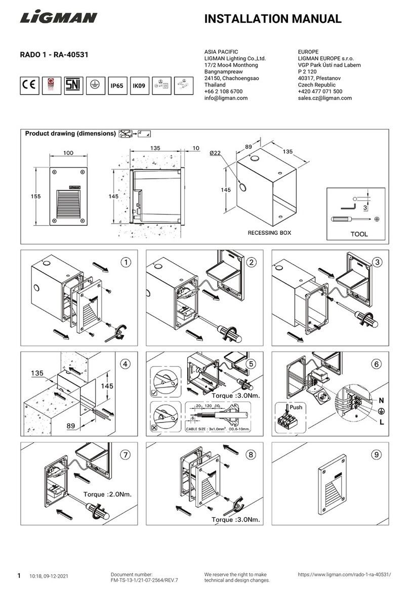
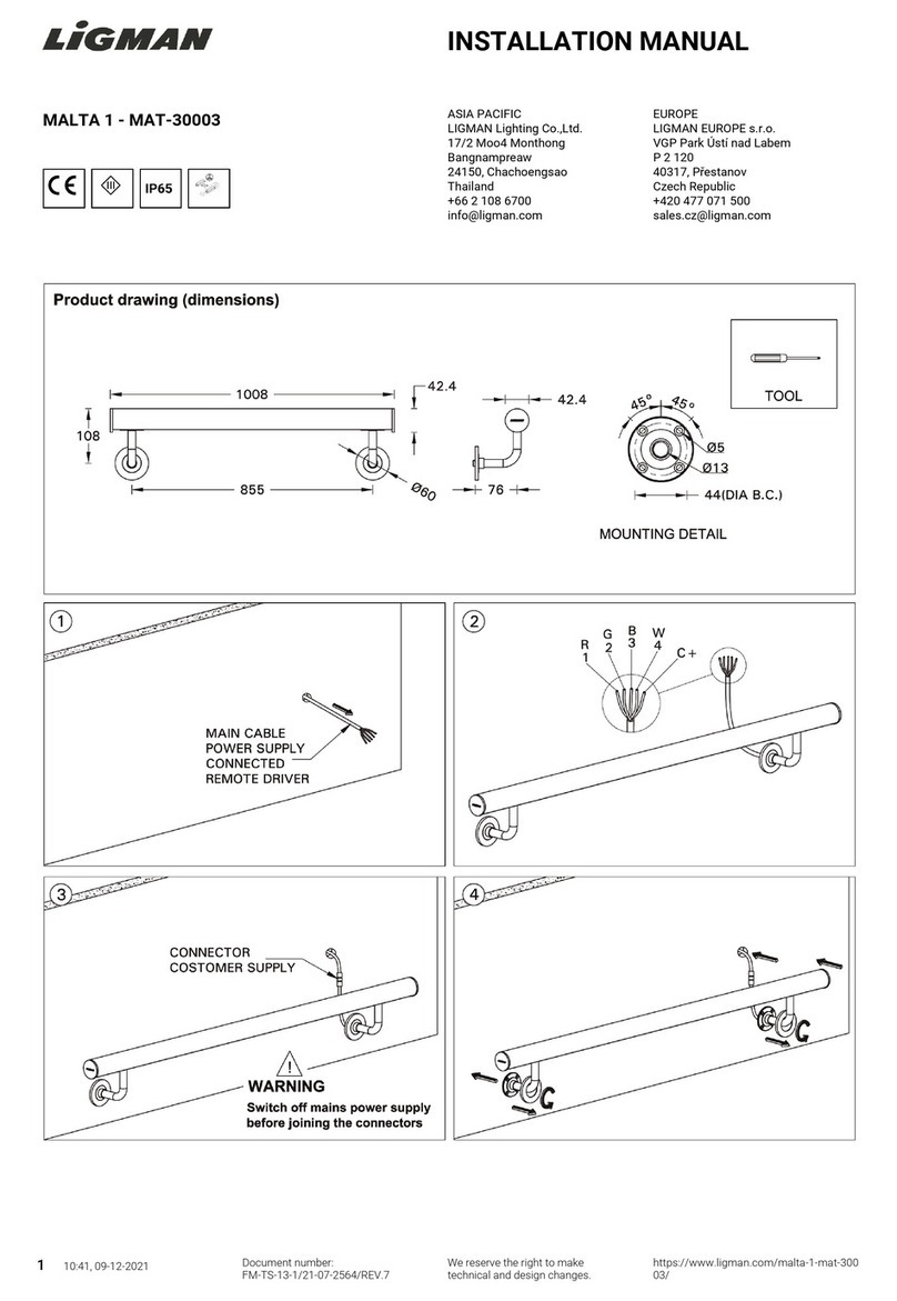
LIGMAN MALTA 1 installation manual

Saxby Lighting
Saxby Lighting Islay 68784 Instruction leaflet

LIGMAN
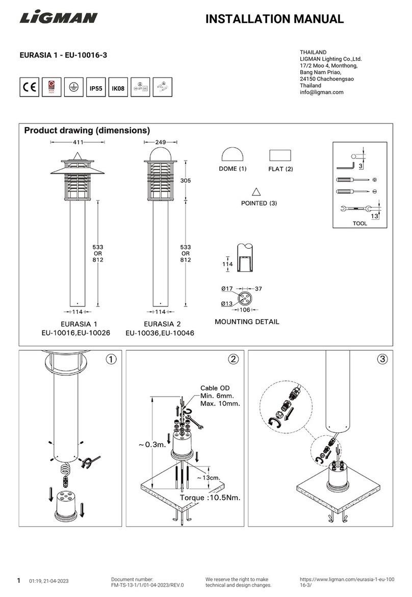
LIGMAN EU-10016-3 installation manual

LIGMAN
LIGMAN KI-60475 installation manual

Cooper Lighting
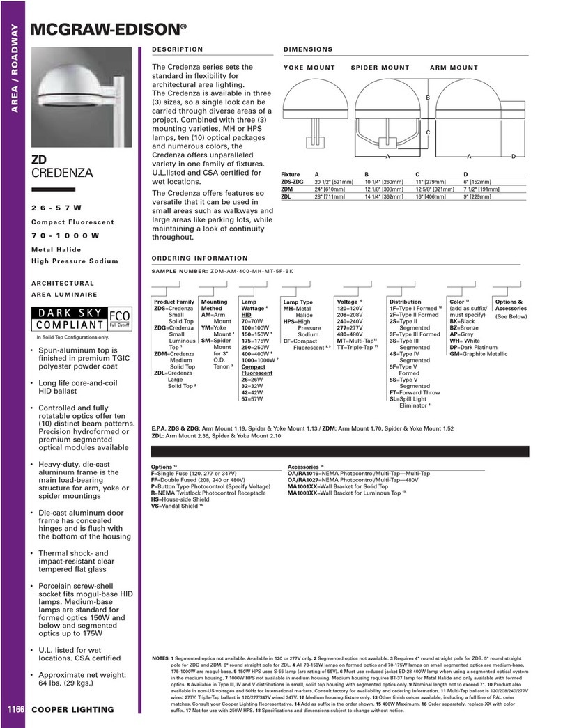
Cooper Lighting McGraw-Edison ZD Credenza specification

Cooper Lighting
Cooper Lighting Generation CLB25MWW5C373 Specification sheet

Malibu Boats
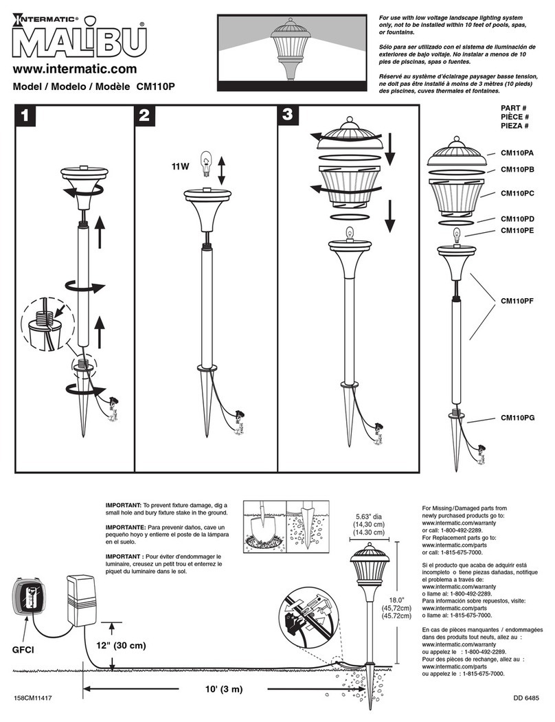
Malibu Boats CM110P instructions

AMP Lighting
AMP Lighting OrchardPro APL-3018-B-BZ Installation & maintenance guide

Cooper Lighting
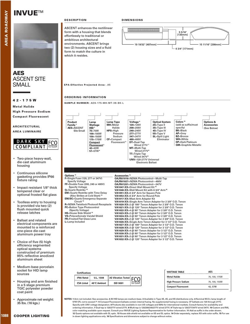
Cooper Lighting Invue 42 - 175W Specification sheet

ABBA
ABBA SPB12 installation guide

Techmar
Techmar Garden Lights GILVUS + manual

LIGMAN
LIGMAN RADO 1 installation manual