Colnatec Tempe User manual

Tempe-Eon™
quick reference guide
A. Sensor Head Inspection
Check for any signs of damage that may have occurred during shipping.
Rotate crystal carousel until
the round opening appears
above an available crystal.
Place rear of sensor head
against the opening.
1. 2.
C. Adding New Crystal
Allow crystal to drop into
sensor head housing.
3.
Use a pair of plastic tweezers
to adjust crystal position until
crystal rests snugly in the
crystal seat.
4.
Rotate retainer ring
COUNTER-CLOCKWISE to
tighten.
Using crystal tool, fit sensor
head retainer ring into place.
Make sure that the flattened
sides correspond to ramp locks
on the inner walls of sensor
head housing.
5. 6.
B. Removing Dummy Crystal*
*Dummy crystal acts as placeholder to protect sensor head during shipping
Turn cap CLOCKWISE to
loosen. Remove cap.
1.
Fit prongs of crystal tool
(included) into opposing
dimples on retainer ring. Turn
CLOCKWISE to remove
retainer ring and access crystal.
2.
To release retainer ring,
turn CLOCKWISE; to
secure, turn COUNTER-
CLOCKWISE. Doing
otherwise may result in
malfunctional hardware
and equipment damage.
Steps C and D of this
user guide describe
proper crystal handling.
WARNING
Always place retaining
ring into sensor head
engraved- side-up. Doing
otherwise may render
sensor head inoperative
and crystal unsecured.
An unsecured crystal
may separate from
sensor head and fall into
chamber.
WARNING
INSPECT PRODUCT
CONDITION ON ARRIVAL
Examine your new Tempe™
and Eon™ for any signs of
physical damage. Make sure
that the tamper-evident
labels are intact. Before
shipping, your Tempe™ and
Eon™ was calibrated and
tested by Colnatec to meet
the highest quality standards.
It is important that you take a
few minutes to inspect the
product to ensure that your
equipment was not damaged
or otherwise tampered with
during transit.
WARRANTY LABEL
If the warranty label has
been tampered with, “VOID”
will appear where the
warranty label was originally
placed. If this is visible at
the time of arrival, it is
important that you contact
Colnatec immediately after
receiving the product.
Length between the Phoenix™
crystal compartment and
Eon™ should NOT exceed 30
inches (76 cm) to avoid erratic
noise levels in oscillation
reading.

1.
D. Chamber Installation
3.
Remove copper gasket from packaging and thread onto sensor head. Fit gasket into circular groove
on conflat.
Hold copper gasket in place
while inserting sensor head
into chamber feedthrough.
2.
BNC Coaxial Cable to
Position
Tempe™
Spin cable in place using cable
shaft until resistance is felt.
(Twisting cable shaft past point
of resistance may damage
cable). Roll fingertip over
connector to tighten.
Heater Control Cable to
Tempe™
The 4-pin LEMO connector
provides heater control and
RTD measurement. To install,
push until it clicks in place.
1. 2.
E. Connecting TempeTM to System
Mirage™Cooling Line to
Tempe™
The cooling line is connected
to the Mirage™via an
insulated cooling tube. Slide
“push-to-connect” fitting onto
the 3/16” cooling pipe
projecting from the Tempe™
flange. Featuring an interior
detent, cooling tube will snap
securely in place.
3.
TempeTM Base Connections
Exhaust Line
Cooling Line
For cooling the sensor head
CAUTION: Extremely
hot air exiting this tube
when mirage is active
LEMO Connection
For heater, power, and control
SMA Coaxial Connection
For crystal frequency
measurement
TempeTM Sensor Head
Crystal Contact
For frequency measurement
reading
Heater Element
Generates enough heat to
remove certain deposits
from crystal
Cap
For safely holding the crystal
and sealing the sensor head
Quartz Crystal
For frequency measurement
CAUTION: Do not attempt to
remove heater
Retainer
Remove with crystal removal
tool
Misaligned coupling of
LEMO connectors can
result in severe damage
to Tempe™.
Hand-tighten flange
bolts before using
wrench, alternating
among bolts and
using a sequential
torque pattern.
4.
Press sensor head and feedthrough flanges together. Align bolt holes.
Apply bolts and plate-nuts. Tightening bolts compresses copper gasket
between a sharp edge and a tapered groove, thus creating a
near-perfect seal.
WARNING
WARNING
Microfractures may
develop in copper
gasket if flange bolts
are over-tightened.
Seal may become
weakened, resulting in
chamber leakage.
Length between the
Tempe™ crystal
compartment and the
Eon™ should NOT
exceed 30 inches (76
cm) to avoid erratic
noise levels in
oscillation reading.

Compressed Air Input to
Mirage™
Connect the Mirage™to a
filtered and oil-free compressed
air source. (Air fittings may vary
by country but require a 1/4
NPT female connection.
Cold Air Output from Mirage™
to Tempe™
Slide the 3/16” tube onto the
“push- to-connect” fitting on rear
of the Mirage™Cooling System.
The Mirage™provides a
maximum output of 28˚C (50˚F)
below the compressed air source.
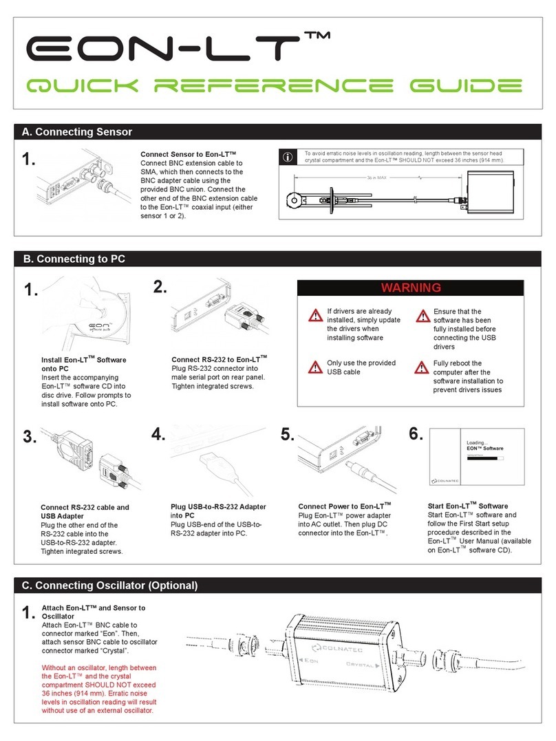
Install Eon™Software
onto PC
Insert the accompanying
Eon™ software CD into
disc drive. Follow prompts
to install software onto PC.
RS-232 to Eon™
Plug RS-232 connector
into male serial port on
rear panel.
RS-232 cable to USB
Adapter
Plug the other end of the
RS-232 cable into the
USB-to-RS-232 adapter.
Plug USB-to-RS-232
Adapter into PC
Plug USB-end of the
USB-to-RS-232 adapter
into PC.
Connect Power to Eon™
Plug Eon™power adapter
into AC outlet. Then plug
DC connector into the
Eon™.
Start Eon™Software
Start Eon™software and
follow the First Start setup
procedure described in the
Eon™ User Manual
(available on the Eon™
software CD).
1. 2.
F. Connecting TempeTM to EonTM
1. 2.
G. Connecting MirageTM to TempeTM and EonTM
1. 2.
H. Connecting EonTM to PC
3.
BNC Coaxial Cable to Eon™
Slide coaxial connector onto
BNC Sensor Input 2. Length
between the Tempe™crystal
compartment and the Eon™
should NOT exceed 30 inches
(30 cm) to avoid erratic noise
levels in oscillation reading.
Heater Control Cable (DB-15
Connector) to Eon™
Plug DB-15 connector into the
Eon™ 15-pin male heater port.
3. Eon™Supplies Power to
Mirage™through Power Module
The 3-pin solenoid module connects
to Mirage™to provide power.
Tighten integrated screw after
mating to Mirage™. The female
DB-9 connector on the other end
attaches to male I/O port on Eon™.
4. Relay Cable from Eon™
to Mirage™
Part of the DB-9 connector
cable bundle that plugs into
the Eon™I/O port and relay
provides a 2-wire interface
for switching.
4.
5. 6.
Ensure that the
software has been fully
installed before
connecting the USB
drivers.
WARNING
If drivers are already
installed, simply update
the drivers when
installing software.
Only use the provided
USB cable.
Fully reboot the
computer after the
software installation to
prevent drivers issues.

While Colnatec tries to include in
your shipment everything you will
need to begin using your new
system, be advised that there are
certain items needed for the
operation of the system that must
be provided by the facilities. This
preparation guide will help you
prepare in advance, ensuring that
all the required items are available
at the time of installation.
511 W. Guadalupe Road, Suite 23 ●Gilbert, AZ 85233 ●480.634.1449 ●[email protected] ●[email protected]
Facilities Requirements
Eon™Computer • Windows XP or newer
• One USB port
• Minimum 1GB free hard disk space
• Minimum 1GB ram
Power • 120-240vac 50/60 Hz Mains
Tempe™All of the required items are included with the shipment
Mirage™Compressed Air Supply • Clean and dry air
• 80 to 100 PSIG
• 25 micron or smaller
• 0.25” NPT
See product CD for a user manual, a
digital copy of this quick-start guide,
and other helpful resources
serial codes
Crystal Buying Guide
ALD, CVD
ALD, CVD
PVD, OLED
ALD, OLED,
CVD
SuperQuartz HT Quartz RC Quartz AT-Quartz
CNT06IG
CNT06IS
CNT06IA
CNT06RCIA
CNT06RCIG
CNT06HTIG
CNT06HTIA
CNT06HTG
CNT06SQG
CNT06SQPN
CNT06SQA
This manual suits for next models
1
Other Colnatec Measuring Instrument manuals
Popular Measuring Instrument manuals by other brands

Igema
Igema TG200 Installation and operation instruction

Sinar Technology
Sinar Technology 6095 AgriPro Operator's manual

TRIMOS
TRIMOS OPTIMA manual

Panasonic
Panasonic DMR-HW220 operating instructions

JB INDUSTRIES
JB INDUSTRIES WH-1 operating manual

Apera Instruments
Apera Instruments LabSen 821 user manual