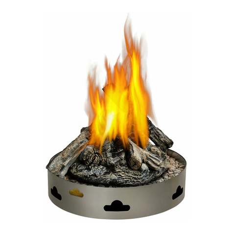
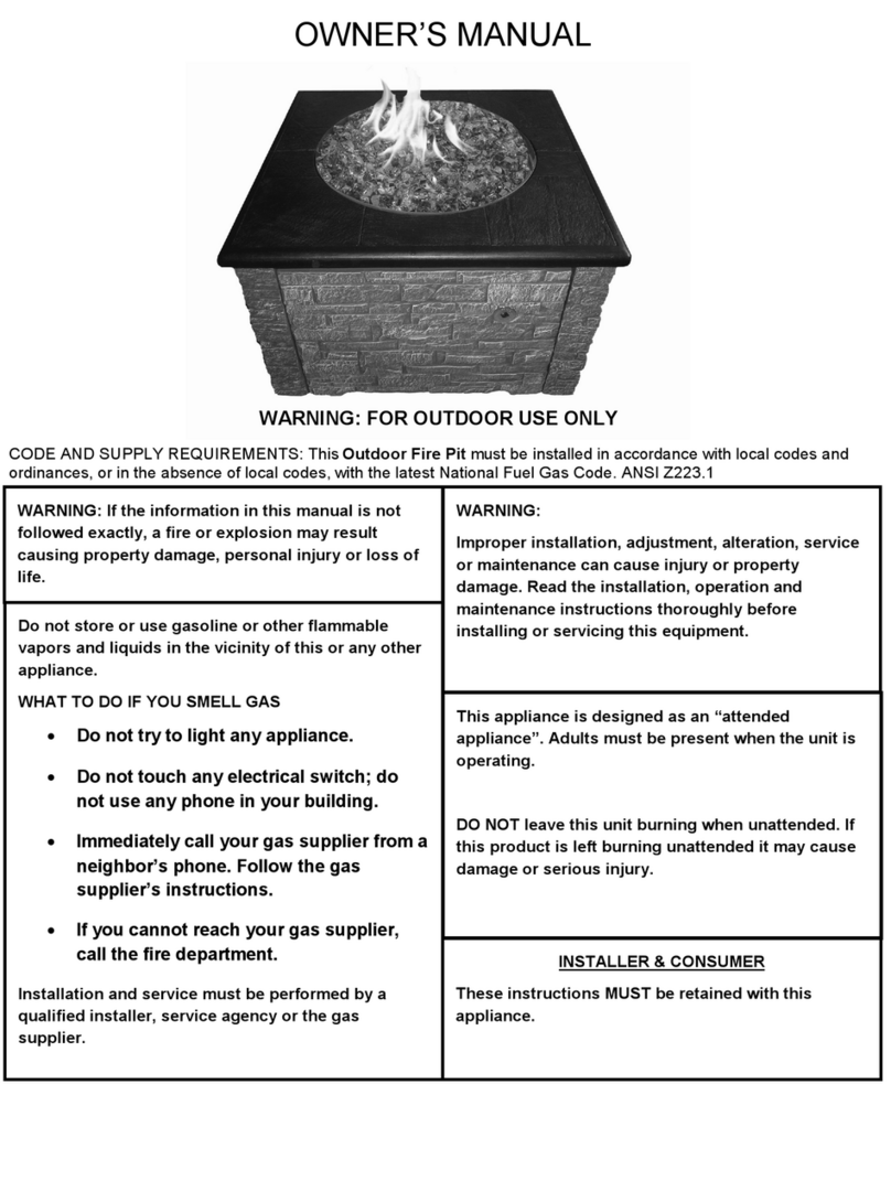
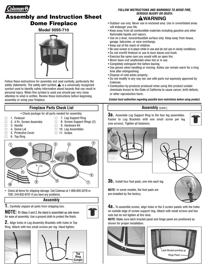
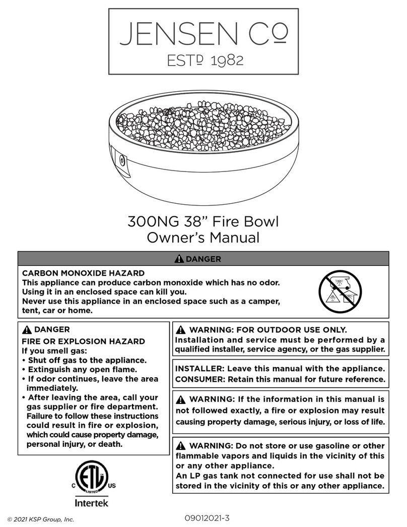
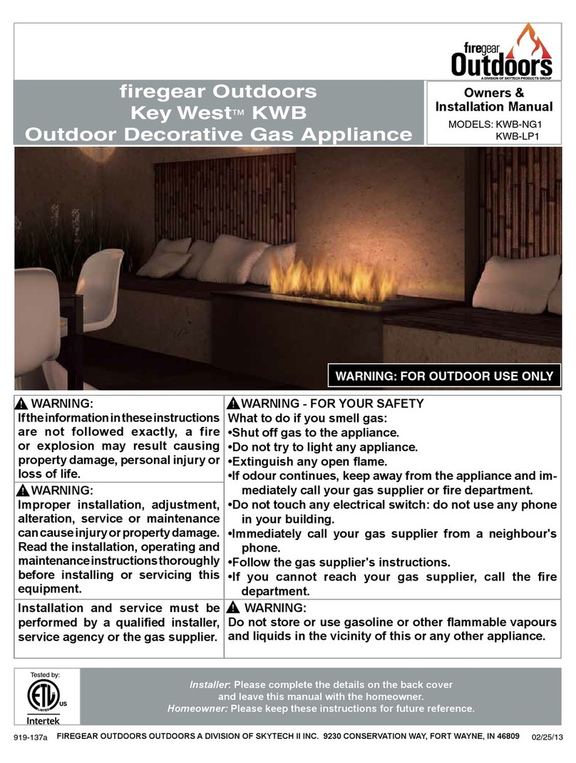
Colombo Construction 54NL User manual

D
P
M
P
N
C
P
D
P
O
T
U
S
V
D
U
J
P
O
D
P
S
Q
P
S
B
U
J
P
O
/
O
F
X
Z
P
S
L
/
D!
P!
M!
P!
N!
C!
P!
D!
P!
O!
T!
U!
S!
V!
D!
U!
J!
P!
O!
D!
P!
S!
Q!
P!
S!
B!
U!
J!
P!
O!
/!
O!
F!
X!
Z!
P!
S!
L!
/!
COLOMBO CONSTRUCTION CORP
342 Park AVE Brooklyn, NY 11205
T 718.399.2233 F 718.399.2237
M
212.334.5069
firefeatures.com
DO NOT STORE OR USE GASOLINE OR OTHER FLAMMABLE VAPORS & LIQUIDS IN THE VICINITY OF
THIS OR ANY OTHER APPLIANCE.
WARNING: If the information in this manual is not followed exactly, a re or explosion may result causing property
damage, personal injury or loss of life.
DO NOT DISCARD THIS MANUAL
• Important operating and maintenance instructions included.
• Read, understand and follow these instructions for safe installation and operation.
• Leave this manual with party responsible for use and operation.
WHAT TO DO IF YOU SMELL GAS:
• Do not try to light any appliance.
• Do not touch any electrical switch; do not use any phone in your building.
• Immediately call your gas supplier from a neighbor’s phone.
• Follow the gas supplier’s instructions.
• If you cannot reach your gas supplier, call the re department.
INSTALLATION & SERVICE MUST BE PERFORMED BY A QUALIFIED INSTALLER, SERVICE AGENCY
OR GAS SUPPLIER.
WARNING: Improper installation, adjustment, alteration, service or maintenance can cause in-
jury or property damage. Read the installation, operating and maintenance instructions thoroughly
before installing or servicing this equipment.
WARNING: FOR OUTDOOR USE ONLY
REMOTE MANUAL PILOT IGNITION
54NL BASE MOUNTED FIREBOWL


REMOTE MANUAL PILOT IGNITION
54NL BASE MOUNTED FIREBOWL
4
5
7
9
10
11
12
13
16
17
18
19
20
Technical Quick View
Warnings
Overview
Burner and Pilot Assembly
Venturi/Orifice
Components
Control Panel
Ignition
Shut off
Emergency / Shut Off
Lava rock
Maintenance
Replacement Parts
TABLE OF CONTENTS
3
CONTENTS

REMOTE MANUAL PILOT IGNITION
54NL BASE MOUNTED FIREBOWL
TECHNICAL
QUICK VIEW
!
4
FOR OUTDOOR USE ONLY
Model: 54NL Base Mounted Firebowl
OUTDOOR FIREFEATURE
Type of Gas: Natural Gas (NG) or Liquid Propane (LP)
ORIFICE SIZES:
NG Maximum BTU = 300,000 w. #K DMS orice @ 7”W.C. Inlet - 6” W.C. Manifold
LP Maximum BTU = 300,000 w. #4 DMS orice @ 11”W.C. Inlet - 10” W.C. Manifold
INSTALLATION BY CERTIFIED GAS TECHNICIAN ONLY
MINIMUM CLEARANCE TO COMBUSTIBLES: Top: 12ft (144”) - Sides: 2ft (24”)
INSTALLATION ON (OR OVER) NON-COMBUSTIBLE FLOORS ONLY.
TO LIGHT APPLIANCE:
• OPERATE AT ARMS LENGTH • DO NOT LEAN OVER APPLIANCE • USE SAFETY GOGGLES & EXTENDED TORCH •
1. MAKE SURE GAS VALVE & FLAME HEIGHT VALVE ARE IN THE OFF POSITION.
2. TURN GAS VALVE COUNTERCLOCKWISE TO THE ON POSITION.
3. TURN FLAME HEIGHT VALVE COUNTERCLOCKWISE TO LOW POSITION.
4. LOCATE PILOT ASSEMBLY ON MAIN BURNER.
5. PUSH RED BUTTON FOR PILOT & HOLD.
6. IMMEDIATELY IGNITE PILOT WITH EXTENDED TORCH - CONTINUE TO HOLD RED PILOT BUTTON DOWN FOR AT
LEAST 30 SECONDS UNTIL PILOT STAYS LIT.
7. RELEASE PILOT BUTTON & REMOVE EXTENDED TORCH FROM PILOT ASSEMBLY MAKE SURE PILOT STAYS LIT.
8. SLOWLY TURN FLAME HEIGHT VALVE COUNTERCLOCKWISE TO HIGH POSITION .
9. ADJUST FLAME HEIGHT TO PREFERENCE.
IF BURNER DOES NOT LIGHT OR YOU SMELL OR HEAR GAS, IMMEDIATELY TURN GAS VALVE CONTROL KNOB ON
APPLIANCE TO OFF POSITION.
TO PUT OUT APPLIANCE:
1. TURN GAS VALVE CLOCKWISE TO OFF POSITION.
2. WAIT FOR GAS TO BURN OUT OF LINE.
3. TURN FLAME HEIGHT VALVE CLOCKWISE TO OFF POSITION.
ALWAYS SHUT DOWN GAS VALVE FIRST, FLAME HEIGHT VALVE SECOND.
TO RE-LIGHT BURNER, WAIT 5 MINUTES AFTER A COMPLETE SHUT-OFF.

REMOTE MANUAL PILOT IGNITION
54NL BASE MOUNTED FIREBOWL
WARNINGS
5
FOR YOUR SAFETY READ BEFORE
OPERATING
!!!!
WARNING: IF YOU DO NOT FOLLOW THESE INSTRUC-
TIONS EXACTLY, A FIRE OR EXPLOSION MAY RESULT
CAUSING PROPERTY DAMAGE, PERSONAL INJURY OR
LOSS OF LIFE.
• IMPROPER INSTALLATION, ADJUSTMENT, ALTERA-
TION, SERVICE OR MAINTENANCE CAN CAUSE INJURY
OR PROPERTY DAMAGE.
• INSTALLATION & GAS CONNECTION MUST BE DONE BY
A CERTIFIED GAS TECHNICIAN, QUALIFIED INSTALLER,
SERVICE AGENCY OR GAS SUPPLIER. FOR ASSISTANCE
OR ADDITIONAL INFORMATION CONSULT A QUALIFIED
INSTALLER, SERVICE AGENCY, OR THE GAS SUPPLIER.
• THIS APLIANCE IS A DECORATIVE GAS APPLIANCE FOR
OUTDOOR USE ONLY AND MUST NOT BE USED FOR COOK-
ING.
COLOMBO CONSTRUCTION CORP disclaims any responsibility
for, and the warranty will be voided by, the following actions:
• Installation & use of any damaged components.
• Modification of the burner & valve assembly.
• Installation other than as instructed by this Owner’s Manual.
• Installation and/or use of any component part not approved
by Colombo Construction Corp.
ANY SUCH ACTION MAY CAUSE A FIRE HAZARD.
The installation of this appliance must conform with local
codes or, in the absence of local codes, with the National Fuel
Gas Code, ANSI Z223.1.
Solid fuels are not to be burned in this gas appliance.
The appliance should be inspected before each use for debris,
damage, or corrosion, and at least annually by a qualified ser-
vice person.
• INSPECT THE APPLIANCE & COMPONENTS.
• DO NOT INSTALL DAMAGED COMPONENTS.
• DO NOT INSTALL INCOMPLETE COMPONENTS.
• REPORT DAMAGED PARTS TO DEALER.
Do NOT use this appliance if any part has been under water.
Immediately call a qualified service technician to inspect the
appliance and to replace any part of the control system and any
gas control which has been under water.
More frequent cleaning may be required as necessary. It is im-
perative that control compartment, burners and circulating air
passageways of the appliance be kept clean to provide for ad-
equate combustion and ventilation air.
This appliance is only for use with the type of gas indicated
on the rating plate. This appliance is not convertible for use
with other gases.
The appliance and its individual shutoff valve must be discon-
nected from the gas supply piping system during any pressure
testing of that system at test pressures in excess of ½ psi.
The appliance must be isolated from the gas supply piping sys-
tem by closing its individual manual shutoff valve during any
pressure testing of the gas supply piping system at test pres-
sures equal to or less than ½ psi.
Children and adults should be alerted to the hazards of high
surface temperatures and should stay away to avoid burns or
clothing ignition. Young children should be carefully super-
vised when they are in the area of the appliance.
Clothing or other flammable materials should not be hung
from the appliance, or placed on or near the appliance.
Any guard or other protective device removed for servicing the
appliance must be replaced prior to operating the appliance.
Use outside only in well ventilated area. Do not use inside
house, camper, tent, garage, vehicle or any type of un-vent-
ed or enclosed area.
Do not operate or place appliance on, near, or in the vicinity
of any flammable materials, vapors, liquids or accelerants of
any kind; including but not limited to: bottled gases, gaso-
line, kerosene, diesel fuel, oil, aerosol cans, paints, thinners,
solvents, sealants, lubricants, chemicals, plastics, petroleum
products, electronics, motors, vehicles, fertilizer, gun pow-
der, ammunition, firearms, fireworks, fabrics, paper prod-
ucts, wood, dry vegetation etc.
Do not operate appliance during an electrical storm.
Appliance must be permanently secured on a stable and
level surface.
Never operate while sleeping or unattended.
REMOTE MANUAL PILOT IGNITION
54NL BASE MOUNTED FIREBOWL
!
Before operating, smell all around the appliance for gas. Do
not operate if you smell gas.
WHAT TO DO IF YOU SMELL GAS OR SUSPECT A LEAK:
IMMEDIATELY SHUT OFF GAS TO THE APPLIANCE AND VEN-
TILATE AREA. DO NOT STRIKE A MATCH, SMOKE OR CREATE
ANY FLAME OR ELECTRIC SPARK. FIND AND CORRECT ANY
LEAKS. USE A SOAP SOLUTION TO DETECT ESCAPING GAS.
DO NOT TOUCH ANY ELECTRICAL SWITCH. DO NOT USE
ANY PHONE IN YOUR BUILDING. IMMEDIATELY CALL YOUR
GAS SUPPLIER. FOLLOW THE GAS SUPPLIER’S INSTRUC-
TIONS. IF YOU CANNOT REACH YOUR GAS SUPPLIER, CALL
THE FIRE DEPARTMENT.
• Use only your hand to turn the gas valve control knob on
the appliance. Never use tools. If the knob will not turn by
hand, do not try to force or repair it yourself. Call a qualified
service technician.
• Forced or attempted repair may result in a fire or explo-
sion.
• Do not touch appliance or gas controls when in operation.
• Do not lean on or into appliance.
• Do not play on or around appliance.
• Do not sit on or step into appliance.
• Do not put hands, feet or any body part on appliance, in
or near flame.
• Do not throw foreign objects or any liquids into appliance.
• Do not operate this appliance under the influence of alco-
hol or drugs.
This appliance does not come supplied with rocks. Lava rocks
are recommended. Some rocks contain water and when
heated will crack, split or burst. Please consult your local
landscape supply for recommendations on which rocks are
best for fires.
• Those connections which could be disturbed when installing,
including, but not limited to the valve train, must be leak test-
ed by a certified gas technician prior to use.
LEAK TESTING PROCEDURE
• Perform a leak test at least once each year whether the gas
supply has been disconnected or not.
• Conduct a leak test anytime the gas supply is connected to
the regulator or any part of the gas system is disconnected
or replaced.
• As a safety precaution, remember to always leak test your
Fire Feature outdoors in a well-ventilated area.
• Never smoke or permit sources of ignition in the area while
doing a leak test.
• Do not use a flame, such as a lighted match to test for leaks.
Use only a leak testing solution as specified below.
Leak Testing Procedure:
1. Prepare a leak testing solution of sudsy water by mixing in
a spray bottle half-liquid soap and half water.
2. Check and make sure all the control knobs are in the OFF
position.
3. Turn gas supply valve counter clockwise one turn to open.
4. Apply leak-testing solution by spraying on joints of the gas
delivery system.
5. Blowing bubbles in the soap solution indicates that a leak
is present.
6. Stop a leak by tightening the loose joint or by replacing
the faulty part with a replacement part recommended by the
manufacturer. Do not attempt to repair the gas supply valve
if it should become damaged. The gas supply valve must be
replaced.
7. If you are unable to stop a leak, close the valve at the gas
supply. Call an authorized gas appliance service technician or
LP gas dealer. Do not use the appliance until the leak is cor-
rected.
8. Push in and turn any control knob to release pressure in the
hose and manifold.
9. Turn off all gas valves and control knobs.
6
WARNINGS
FOR YOUR SAFETY READ BEFORE
OPERATING

REMOTE MANUAL PILOT IGNITION
54NL BASE MOUNTED FIREBOWL
OVERVIEW
FIRE FEATURE
7

REMOTE MANUAL PILOT IGNITION
54NL BASE MOUNTED FIREBOWL
OVERVIEW
8
3 VIEW 54NL
PLAIN VIEW / SAFETY SHUT OFF VALVE - THIS VALVE IS USED TO STOP THE SUPPLY
OF GAS TO THE APPLIANCE IN THE EVENT OF AN EMERGENCY. THIS VALVE MUST BE
INSTALLED WITHIN 10’- 15’ (FEET) OF THE APPLIANCE. IT MUST BE CLEARLY LABELED
AND NOT HIDDEN.
EACH APPLIANCE IS SUPPLIED WITH A GAS REGULATOR AND IT SHOULD BE INSTALLED
WITH IN 10’- 15’ (FEET) OF THE APPLIANCE.
3/4" GAS LINE CONNECTION IN
SECTION A
SECURE BOWL THROUGH THE CENTER HOLE OF THE BOWL
3/8" HARDWARE
16"
14"
2"
SECTION B
PILOT BURNER AND THERMOCOUPLE
4"
20"
54" DIA
54NL FIREBOWL
PILOT BURNER AND THERMOCOUPLE
DISTANCE BETWEEN PILOT ASSEMBLY
AND PUSH FOR PILOT CAN BE NO GREATER
THAN 36" APART
SHOWN @ 17"
36" MAX
SECTION
A
SECTION
A3 3/4"
13 5/8"
TOP VIEW
SECTION
SECTION
B
B
CONTROL BOX
72"
72"

REMOTE MANUAL PILOT IGNITION
54NL BASE MOUNTED FIREBOWL
BURNER AND
PILOT
ASSEMBLY
PART COMPONENTS
LEGEND
1. Pilot Guard
2. Baso Thermocouple K16RM-180H
3. Baso Pilot Assembly - J992MDA-2
4. Main Burner
9

REMOTE MANUAL PILOT IGNITION
54NL BASE MOUNTED FIREBOWL
VENTURI/
ORIFICE
OXYGEN INTAKE ADJUSTMENT
The Venturi is located under the base of the
firefeature. The Venturi positioning keeps
the flame looking yellow and natural.
The more oxygen you let in, the smaller
and bluer the flame. If the oxygen is shut
off completely, the flame will contain more
soot and unburned contaminents.
You may adjust the Venturi according to
visual preference.
10
1
2
3
LEGEND
Brass Orifice
Venturi Adjustable Air Shutter
90M Stainless Steel Venturi Air Mixer

REMOTE MANUAL PILOT IGNITION
54NL BASE MOUNTED FIREBOWL
COMPONENTS
BURNER COMPONENT PARTS
11
All replacement parts may be ordered
by calling Colombo Construction Corp.
718.399.2233 or 212.334.5069 or by
emailing [email protected]
LEGEND
Lid / Lighting Instructions
Gas Line To Burner
Flame Height Control Valve
Thermocouple Line
Press for Pilot Button
On/Off Gas Valve
Gas Line In
Pilot Gas Line
Control Panel Back Plate
Control Panel
1.
2.
3.
4.
5.
6.
7.
8.
9.
10.

REMOTE MANUAL PILOT IGNITION
54NL BASE MOUNTED FIREBOWL
IN THE OFF POSITION
LEGEND
3/4” Ball Valve (Flame adjustment)
Pilot Button - H15DA-3C Baso Safety Valve
3/4” Gas Ball Valve (On/Off)
1
2
3
CONTROL
PANEL
12
Off Position

REMOTE MANUAL PILOT IGNITION
54NL BASE MOUNTED FIREBOWL
13
IGNITION
TO LIGHT PILOT
• Operate at arms length.
• Do not lean over the appliance.
• Use safety-goggles and a extended torch.
Make sure gas valve and flame height valve
are in the OFF position.
Turn gas valve counterclockwise to the
ON position.
Locate pilot assembly on main burner.
IGNITION CONTINUES ON THE NEXT
PAGE
A.
B.
C.
A.
B.
C.

REMOTE MANUAL PILOT IGNITION
54NL BASE MOUNTED FIREBOWL
14
TO LIGHT PILOT
• Operate at arms length.
• Do not lean over the appliance.
• Use safety-goggles and a extended torch.
Turn flame height valve counterclockwise to
LOW position.
Immediately ignite pilot with extended torch -
continue to hold red pilot button down for at
least 30 seconds until pilot stays lit.
Release pilot button & remove extended torch
from pilot assembly and make sure pilot stays
lit.
Slowly turn flame height valve counterclock-
wise to HIGH position.
Adjust flame height to preference.
IGNITION CONTINUES ON THE NEXT
PAGE
IGNITION
D.
E.
F.
D.
E.
F.

REMOTE MANUAL PILOT IGNITION
54NL BASE MOUNTED FIREBOWL
15
IGNITION
SUCCESSFUL IGNITION
If main burner does not light, or you smell
or hear gas, immediately turn gas valve &
flame height valve to off position. Wait 5
minutes and repeat steps B to F.

REMOTE MANUAL PILOT IGNITION
54NL BASE MOUNTED FIREBOWL
16
SHUT-OFF
TO PUT BURNER OUT
Turn gas valve clockwise to OFF position.
Wait for gas to burn out of line.
Wait for burner to fully extinguish.
Turn flame height valve clockwise to OFF
position.
Always shut down gas valve first, flame height
valve second.
To re-light burner, wait 5 minutes after a
complete shut-off.
A.
A.
B.
C.
B.
C.

REMOTE MANUAL PILOT IGNITION
54NL BASE MOUNTED FIREBOWL
EMERGENCY/
SHUT-OFF
PLAIN VIEW SHUT-OFF
TO PUT BURNER OUT
In the event of a uncontrolled fire,
always be aware of where the emergency
shut-off valve is located.
OFF POSITION
17

REMOTE MANUAL PILOT IGNITION
54NL BASE MOUNTED FIREBOWL
LAVA ROCK ONLY
Lava rocks are the recommended rock for
use in the firebowl. Lava rock is best suited
because it was made by heat and therefore
does not react when used in a high heat en-
vironment; it is also light weight and readily
available.
Lava rocks come in all sizes, from pebbles to
boulders. 4” to 10” is the best size to use
with your firebowl. You will need approxi-
mately 100 to 200lbs for the firebowls.
Please contact the following website to or-
der lava rocks if you are unable to find any
at your local garden supply store:
http://www.fountainsnslate.com/
1-800-643-5804 or 1-386-586-4062
WARNING: Other rocks may contain water,
and when heated will split, crack or burst
and are therefore to be used at your own
risk and not recommended.
ROCKS
18
WARNIN
G:
Other rocks may contain water,
and when heated will split, crack or burst
and are therefore to be used at your own
ris
k a
nd
not recommen
ded
.

REMOTE MANUAL PILOT IGNITION
54NL BASE MOUNTED FIREBOWL
MAINTENANCE
Properly maintained, your decorative gas ap-
pliance will provide years of useful service. A
regular routine maintenance program such as
the program outlined below should be estab-
lished and followed. It is further recommend-
ed to follow the maintenance procedures on
safety valves and other accessory equipment
according to the manufacturers instructions.
It is recommended to have at least one annual
inspection performed by a certified gas tech-
nician.
Routine Preventive Maintenance:
Have the appliance serviced and leak checked
annually by a qualified service technician.
Keep the area inside and around the ap-
pliance and base free of debris, foreign
matter, or obstruction. Regularly remove all
broken rock chips, leaves, branches, grass, etc
from fire feature on a daily or weekly basis.
Clean any corrosion or scale off burner, con-
trol panel, and venturi with a wire brush.
Make sure that venturi remains set in position.
See page 12.
Visually inspect the burner regularly both
while firing and while turned off. Replace any
corroded parts.
Visually inspect pilot while main burner is on
and while main burner is off. Replace any cor-
roded parts. Be certain that pilot position is
correct and that pilot reliably and accurately
ignites main burner.
Use a tooth pick or thin wire to poke out any
clog or obstruction from the small holes in the
burner, only when the burner is off.
Check to be certain that the area the gas
equipment operates in is free of obstruction.
Remember, that for proper combustion, prop-
er operation, and proper ventilation, flow of
air around your gas equipment must be un-
obstructed. Never store combustible materials
or flammable liquids near any gas equipment.
When burners are not in use for a long time,
or are used only seasonally, care should be
taken to wire brush scale off burners and
inside venturi. An air compressor can be
used to blow out cobwebs or nests which may
clog orifices.
*If any unusual behavior of the gas equip-
ment is noted during inspection, shut the
burner off until qualified service assistance
can be obtained.
*For your safety, all repairs on the burner sys-
tem should be performed by qualified service
personnel only as it involves disconnecting gas
supply and performing leak testing.
MAINTENANCE
A.
B.
C.
D.
E.
F.
G.
H.
19
can be obtained.
*For your safety, all repairs on the bu
tem should be performed by qualified
personnel only as it involves disconnec
supply and performing leak testing.

REMOTE MANUAL PILOT IGNITION
54NL BASE MOUNTED FIREBOWL
VALVE TRAIN ASSEMBLY:
1. Connecting Pipe Assembly
2. T1001 Legend 3/4” Brass Ball Valve (2x)
3. Brass Extension Handle (2x)
4. Metal Valve Handle (2x)
5. Baso Safety Valve H15DA-3C
PILOT ASSEMBLY:
6. Baso Pilot Assembly - J992MDA-2
7. Baso Brass Pilot Orifce -
Assembly Includes NG or LP Orifice
8. 1/4” O.D. Pilot Light Feed Tubing
9. Baso Thermocouple K16BA-60
MAIN BURNER ASSEMBLY:
10. Main Burner
11. Stainless Steel Venturi Air Mixer
12. Stainless Steel Air Shutter
13. Brass Orifce Assembly
REPLACEMENT
PARTS
20
All parts may be ordered by calling Colombo Construction Corporation 212.334.5069
or emailing elena@firefeatures.com
Table of contents
Other Colombo Construction Outdoor Fireplace manuals
Popular Outdoor Fireplace manuals by other brands

The Fireplace
The Fireplace JETMASTER 700 D installation instructions

Superior
Superior VRE4543EN Installation and operation instructions

Napoleon
Napoleon PATIOFLAME GPFN Installation and operation instructions

Endless Summer
Endless Summer Dakota GAD19101ES owner's manual

Vermont Castings
Vermont Castings ODGSR36A Homeowner's installation and operating manual

FEUERHAND
FEUERHAND PYRON user manual