Color imagination SI-052 User manual

90W
90W
90W
90W LED
LED
LED
LED Moving
Moving
Moving
Moving Head
Head
Head
Head Spot
Spot
Spot
Spot
SI-052
SI-052
SI-052
SI-052
User
User
User
User Manual
Manual
Manual
Manual
KEEP
KEEP
KEEP
KEEP THIS
THIS
THIS
THIS MANUAL
MANUAL
MANUAL
MANUAL FOR
FOR
FOR
FOR FUTURE
FUTURE
FUTURE
FUTURE NEEDS
NEEDS
NEEDS
NEEDS
1
1
1
1 1
1
1
1 .
.
.
. Maintenance
Maintenance
Maintenance
Maintenance and
and
and
and Cleaning
Cleaning
Cleaning
Cleaning
The following points have to be considered during the inspection:
1) All screws for installing the devices or parts of the device have to be tightly connected and must not be
corroded.
2) There must not be any deformations on the housing, color lenses, fixations and installation spots (ceiling,
suspension, trussing).
3)Mechanically moved parts must not show any traces of wearing and must not rotate with unbalances.
4)The electric power supply cables must not show any damage, material fatigue or sediments.
Further instructions depending on the installation spot and usage have to be adhered by a skilled installer
and any safety problems have to be removed.
In order to make the lights in good condition and extend the life time, we suggest a regular cleaning to the
lights.
1) Clean the inside and outside lens each week to avoid the weakneness of the lights due to accumulation
of dust.
2) Clean the fan each week.
3) A detailed electric check by approved electrical engineer each three month, make sure that the circuit
contacts are in good condition, prevent the poor contact of circuit from overheating.
We recommend a frequent cleaning of the device. Please use a moist, lint- free cloth. Never use alcohol or
solvents.
There are no serviceable parts inside the device. Please refer to the instructions under “ Installation
instructions ” .
Should you need any spare parts, please order genuine parts from your local dealer.

1.
1.
1.
1. Dispacking
Dispacking
Dispacking
Dispacking
Thank you for Color Imagination
’
s 90W LED Moving Head Spot . For your own safety, please read
this manual before installing the device. This manual covers the important information on
installation and applications. Please install and operate the fixture with following instructions.
Meanwhile, please keep this manual well for future needs.
Color Imagination
’
s 90W LED Moving Head Spot is made of a new type of high temperature
strength of engineering plastics and cast aluminum casing with nice outlook. The fixture is designed
and manufactured strictly following CE standards, complying with international standard DMX512
protocol. It
’
s available independently controlled and linkable with each other for operation. And it is
applicable for large-scale live performances, theater, studio, nightclubs and discos.
SI-052 adopts powerful Luminus 90W CBM-360-W which features high brightness and stability.
Please carefully dispack it when you receive the fixture and check whether it is damaged during the
transportation. And please check whether the following items are included inside the box:
Moving Head---- -----one Signal Cable----one
Omega Clamp------ -Two User Manual----one
Safety Chain---------One
220-239 Internal program 7
240-255 Internal program 8
9.
9.
9.
9. Key
Key
Key
Key Features
Features
Features
Features
Luminus high power 9 0W white LED unit ( CBM-360-W ) With e qual o utput to 575 W d ischarge
50,000 hours lifespan and low power consumption
16 bit smooth and precise resolution for PAN/TILT movement
540 ° /630 ° pan and 270 ° tilt movement
Scan position memory, auto reposition after unexpected movement
1 color wheel with 7 d ichroic c olors plus open
Variable direction r ain bow effect with speed adjustable
1 rotatable gobo wheel with 7 rotatable interchangeable gobos plus open (3 metal gobos and 4
glass gobos) with speed adjustable, stream effect, dithering effect and rotatable clockwise or
anticlockwise
1 static gobo wheel with 9 fixed gobos plus open
1 rotatable 3-facet prism with speed adjustable and variable direction
2 meter to infinite electric focus
1 5 º projection beam angle
Electronic linear IRIS
0-100% linear dimmer with 1- 18 times/sec high speed electronic strobe
LED shutter with variable speed
1 5 DMX channels
10.
10.
10.
10. Technical
Technical
Technical
Technical Specifications
Specifications
Specifications
Specifications
Input Voltage: AC90-260V 50-60Hz
LED Quantities: 1* 9 0W High brightness white LED unit
Control Signal: DMX512, master-slave and sound activated or auto operation
Control Channel: 15 DMX Channels
Power Consumption: 240W
Dimensions: 203 x 300 x 437 mm
Packing Dimensions: 253 x 350 x 487 mm
Net Weight:
1
1 kgs
Gross Weight: : 1 2.5 kgs

9 7 1 Shutter
064 - 095 Strobe effect slow to fast
096-127 shutter open
128 - 159 Pulse-effect in sequences
16 0- 191 shutter open
192-223 Random strobe effect slow to fast
224-255 shutter open
10 8 2 Dimmer 0-255 0-100% Linear dimmer
11 9 8 Focus 0-255 In(near) to out(far)
12 10 9
Rotating
Prism,
Prism,
Gobo
Macros
0-005 Prism swing out
006-127 Prism swing in
128-189 Forwards rotation from fast to slow
190-193 Prism rotation stop
194-255 Backwards rotation from slow to fast
13 11 7 Iris
0-191 Max. diameter to Min.diameter
192-223 Pulse opening fast to slow
224-255 Pulse closing slow to fast
14 12 12
Speed of
Pan/Tilt
0-225 Max to min speed
226-235 Blackout by movement
236-245 Blackout by all wheel changing
246-255 No function
15 13 13 Special
0-019 No function
020-029 No function
030-039 No function
040-079 No function
080-099 Motor reset
100-119 Internal program 1
120-139 Internal program 2
140-159 Internal program 3
160-179 Internal program 4
180-199 Internal program 5
200-219 Internal program 6
2.
2.
2.
2. S
S
S
S afety
afety
afety
afety I
I
I
I nstructions
nstructions
nstructions
nstructions
This device has left the factory in perfect condition. In order to maintain this condition and to ensure a
safe operation, it is absolutely necessary for the user to follow the safety instructions and warning
notes written in this user manual.
If the device has been exposed to temperature changes due to environmental changes, do not switch
it on immediately. The arising condensation could damage the device. Leave the device switched off
until it has reached room temperature.
This device falls under protection-class I. Therefore it is essential that the device be earthed.
The electric connection must carry out by qualified person.
The device shall only be used with rate voltage and frequency.
Make sure that the available voltage is not higher than stated at the end of this manual.
Make sure the power cord is never crimped or damaged by sharp edges. If this would be the case,
replacement of the cable must be done by an authorized dealer.
Always disconnect from the mains, when the device is not in use or before cleaning it. Only handle the
power cord by the plug. Never pull out the plug by tugging the power cord.
During initial start-up some smoke or smell may arise. This is a normal process and does not
necessarily mean that the device is defective, it should decrease gradually.
Please don't project the beam onto combustible substances.
Fixtures cannot be installed on combustible substances, keep more than 50cm distance with wall for
smooth air flow, so there should be no shelter for fans and ventilation for heat radiation.
If the external flexible cable or cord of this luminaire is damaged, it shall be exclusively replaced by the
manufacturer or his service agent or a similar qualified person in order to avoid a hazard.

3.
3.
3.
3. Operation
Operation
Operation
Operation Instructions
Instructions
Instructions
Instructions
-The moving head is for beam effect for onsite decoration purpose .
-Don ’ t turn on the fixture if it
’
s been through severe temperature difference like after
transportation because it might damage the light due to the environment changes. So make sure
to operate the fixture until it is in normal temperature .
- This light should be keep away from strong shaking during any transportation or movement.
-Don ’ t pull up the light by only the hea d, or it might cause damages to the mechanical parts.
- Don ’ t expose the fixture in overhea t, moisture or environment with too much dust when installing
it. And don ’ t lay any power cables on the floor. Or it might cause electronic shock to the people.
- Make sure the installation place is in good safety condition before installing the fixture.
-Make sure to put the safety chain and check whether the screws are screwed properly when
installing the fixture.
- Make sure the lens are in good condition. It
’
s recommended to replace the units if there are any
damages or severe scratch.
- Make sure the fixture is operated by qualified personnel who knows the fixture before using.
- Keep the original packages if any second shipment is needed.
- Don ’ t try to change the fixtures without any instruction by the manufacturer or the appointed
repairing agencies.
-It is not in warranty range if there are any malfunctions from not following the user manual to
operate or any illegal operation, like shock short circuit, electronic shock, lamp broke, etc.
4.
4.
4.
4. Mounting
Mounting
Mounting
Mounting and
and
and
and Installation
Installation
Installation
Installation
Cautions:
Cautions:
Cautions:
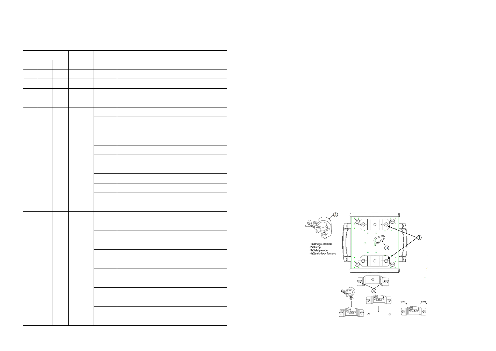
Cautions: For added protection mount the fixtures in areas outside walking paths, seating areas,
or in areas were the fixture might be reached by
unauthorized person nel .
Before mounting the fixture to any surface, make sure that the installation area can hold a
minimum point load of 10 times the device
’
s weight.
Fixture installation must always be secured with a secondary safety attachment, such as an
appropriate safety cable.
Never stand directly below the device when mounting, removing, or servicing the fixture.
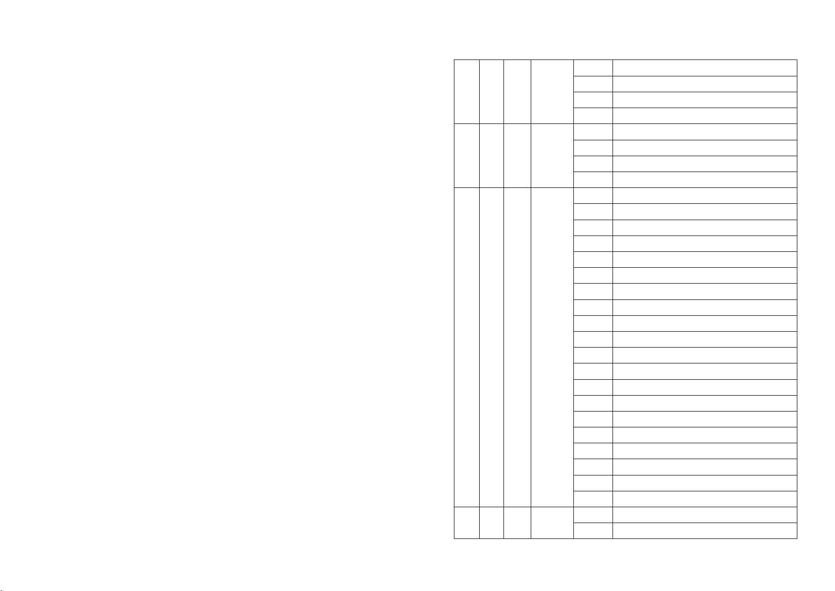
160-179 Gobo 5 shake slow to fast
180-199 Gobo 6 shake slow to fast
200 - 219 Gobo 7 shake slow to fast
220 - 255 Rot. gobo wheel cont. rotation slow to fast
7 5 5
Gobo 1
Rot.
0-127 Gobo indexing
128-189 Forwards gobo rotation from fast to slow
190-193 Gobo rotation stop
194-255 Backwards gobo rotation from slow to fast
8 6 6 Gobo 2
0 - 009 Open/hole
010 - 019 Gobo 1
020 - 029 Gobo 2
030 - 039 Gobo 3
040 - 049 Gobo 4
050 - 059 Gobo 5
0 60 - 069 Gobo 6
070-079 Gobo 7
080-089 Gobo 8
090-099 Gobo 9
100-111 Gobo 1 shake slow to fast
112-123 Gobo 2 shake slow to fast
124-135 Gobo 3 shake slow to fast
136-147 Gobo 4 shake slow to fast
148-159 Gobo 5 shake slow to fast
160-171 Gobo 6 shake slow to fast
172 -1 83 Gobo 7 shake slow to fast
184-195 Gobo 8 shake slow to fast
196-207 Gobo 9 shake slow to fast
208-255 Gobo wheel rotation from slow to fast
0- 031 Shutter closed
032 - 063 shutter open

8.DMX
8.DMX
8.DMX
8.DMX Channels
Channels
Channels
Channels
Mode/Channel
Mode/Channel
Mode/Channel
Mode/Channel Function
Function
Function
Function Values
Values
Values
Values Description
Description
Description
Description
16B 8B DE
1 1 10 Pan 0-255 PAN Movement
2 Pan Fine 0-255 Fine control of Pan movement
3 2 11 Tilt 0-255 Tilt Movement
4 Tilt Fine 0-255 Fine control of Tilt movement
5 3 3 Color
0- 0 1 5 Open/White
0 1 6 - 031 Color 1
032 - 0 4 7 Color 2
0 4 8 - 063 Color 3
064 - 079 Color 4
08 0- 095 Color 5
096 - 111 Color 6
112 -1 27 Color 7
1 28 -1 89 Forwards rainbow effect from fast to slow
1 90 - 193 Color rotation stop
194 -255 Backwards rainbow effect from slow to fast
6 4 4 Gobo 1
0- 009 Open
010 - 0 1 9 Gobo 1
020 - 0 2 9 Gobo 2
030 - 039 Gobo 3
040 - 049 Gobo 4
050 - 059 Gobo 5
060 - 069 Gobo 6
070 - 079 Gobo 7
080-099 Gobo 1 shake slow to fast
100-119 Gobo 2 shake slow to fast
120-139 Gobo 3 shake slow to fast
140-159 Gobo 4 shake slow to fast
from a ceiling, or set on a flat level surface (see illustration below). Be sure this fixture is kept at
least 0.5m (1.5 ft) away from any flammable materials (decoration etc.).
Always use and install the supplied safety cable as a safety measure to prevent accidental damage
and/or injury in the event the clamp fails.
Mounting
Mounting
Mounting
Mounting points
points
points
points :
:
:
:Overhead mounting requires extensive experience, including amongst others
calculating working load limits, a fine knowledge of the installation material being used, and
periodic safety inspection of all installation material and the fixture. If you lack these qualifications,
do not attempt the installation yourself. Improper installation can result in bodily injury.
Be sure to complete all rigging and installation procedures before connecting the main power
cord to the appropriate wall outlet.
Clamp
Clamp
Clamp
Clamp Mounting
Mounting
Mounting
Mounting :
:
:
:The Spot LED provides a unique mounting bracket assembly that integrates the
bottom of the base, the included “ Omega Bracket, ” and the safety cable rigging point in one unit
(see the illustration below). When mounting this fixture to truss be sure to secure an appropriately
rated clamp to the included omega bracket using a M10 screw fitted through the center hole of
the “ omega bracket
”
. As an added safety measure be sure to attached at least one properly rated
safety cable to the fixture using on of the safety cable rigging point integrated in the base
assembly

Regardless of the rigging option you choose for your SPOT LED, always be sure to secure your fixture with
a safety cable. The fixture provides a built-in rigging point for a safety cable on the hanging bracket as
illustrated above. Be sure to only use the designated rigging point for the safety cable and never secure a
safety cable to a carrying handle.
5.
5.
5.
5. DMX-512
DMX-512
DMX-512
DMX-512 control
control
control
control connections
connections
connections
connections
Connect the provided XLR cable to the female 3-pin XLR output of your controller and the other side to the
male 3-pin XLR input of the moving head. You can chain multiple
Moving head together through serial linking. The cable needed should be two core, screened cable with
XLR input and output connectors. Please refer to the diagram below.
DMX-512 connection with DMX terminator
For installations where the DMX cable has to run a long distance or is in an electrically noisy environment,
such as in a discotheque, it is recommended to use a DMX terminator. This helps in preventing corruption
of the digital control signal by electrical noise. The DMX terminator is simply an XLR plug with a 120 Ω
resistor connected between pins 2 and 3,which is then plugged into the output XLR socket of the last
fixture in the chain. Please see illustrations below.
1
1
1
1
2
2
2
2
3
3
3
3
PIN 3
PIN 3
PIN 3
PIN 3
PIN 2
PIN 2
PIN 2
PIN 2
120
120
120
120
Ω
6.
6.
6.
6. Menu
Menu
Menu
Menu Operations
Operations
Operations
Operations
DMX Address A001~AXXX Change Address
Auto Play Auto Run Master/Alone
Music Control Master/Alone
Reset On/Off
Reverse Pan On/Off
Reverse Tilt On/Off
Mic Sensitivity 0~99%
Special Reset Default On/Off
Calibration Code (Password :088 )
PAN,
TILT,
Color Wheel, Gobo Wheel 1, Gobo Wheel 2,
Focus ,Prism
Temperature
XXX ℃/℉
Current Temperature
Manual Control PAN=XXX ……
Edit Program Auto
Program1
…
Program8
Steps(1..48) Set Step
Scenes 01
…
Scenes XX
Pan=XXX …
…
Time=xx.xS
Set each scene ’s
channel value and
running time
7.
7.
7.
7. Photometric
Photometric
Photometric
Photometric Data
Data
Data
Data
Table of contents
Popular Spotlight manuals by other brands

TECH LIGHT
TECH LIGHT ST-3327 user manual

LIVARNO home
LIVARNO home 1002-W manual

Project Source
Project Source 16438-003 quick start guide

Anslut
Anslut 001-566 operating instructions

Guangzhou Yinhe Lighting&Sound Equipment Factory
Guangzhou Yinhe Lighting&Sound Equipment Factory NE-204 user manual

Federal Signal Corporation
Federal Signal Corporation VISIBEAM II Installation, operation and maintenance instructions

M&M
M&M EFESO instruction sheet

Philips
Philips SpotOn Original 6918930PH brochure

Cool lights
Cool lights CL-MF0070 Operation manual

Conrad Electronic
Conrad Electronic 75 LED Spot operating instructions

ProLights
ProLights Astra Hybrid420IP user manual

SLV Elektronik
SLV Elektronik SLEEK SPOT G12 quick start guide