SAVE THESE INSTRUCTIONS
NOITCURTSNINOITALLATSNIS
04272021
COLORONIX |WWW.RGBW.COM | PH. 323.677.4242 | A DIVISION OF EEMA LIGHTING GROUP | ALL RIGHTS RESERVED• Product specifications subject to change without notice.
(For In-Grade: Including Poured Concrete)
Page 7 – Coloronix SG3-RGBW-3R RGBW Pathway / In-Ground DMX Light Manual V2.1.2
CATALOG # :
INSTALLATION INSTRUCTIONS for SG3-RGBW-3R
SG3-RGBW-3R
- Make sure to keep any and all debris as well as water, snow and/or ice off of top of fixture at
all times!
- Installation should not be done under high humidity (e.g. rainy day or after rain, foggy
weather... etc.).
- If moisture is observed in fixture, remove trim and glass from fixture. Dry fixture thoroughly
and operate lamp to remove moisture.
- Periodically check lens for cracks, check lens gasket for cracks, worn, Torx and/or if it badly
deformed and replace as needed with factory parts only.
- When installing trim center the lens and gasket in housing.
- Periodically check screw tightness on the trim that holds the lens in place and tighten. Clean
lens as need.
READ AND UNDERSTAND ALL INSTALLATION INSTRUCTIONS BEFORE INSTALLING FIXTURE!
Fixture Installation:
Warning: Check that the power output for the DC voltage is 24V DC before connecting power to fixture. Also
check that the measured DC voltage at the fixture is 23.1V dc (minimum). See “Coloronix Maximum Cable
Length Chart For Single Runs" page 8.
1. Connect input and RGBW / DMX / RJ45 wires to the RGBW cord from this fixture per this manual.
2. If using the Coloronix Constant Voltage DMX512 Decoder # SDE24V24RGBW-400-16BIT (or any other
Coloronix product) then also follow those instructions in addition to the instructions in this manual.
• Danger: Always disconnect power before wiring, or maintenance. Fixture must be installed by a qualified electrician. Fixture
must always be installed according to local and national electrical codes, rules & regulations. Fixture must be installed on a
circuit protected by Ground Fault Circuit Interrupter (GFCI).
• Warning: Seal all conduit opening(s) and opening(s) from water entry. Before service ensure fixture is cool to touch. Always
ensure that all gaskets and sealing surfaces are free of dirt and debris.
WARNING: RISK OF SHOCK. Check fixture for input voltage before connecting power to fixture.
This fixture is suitable for dry, damp and wet locations. Also for use with poured concrete.
LED fixture(s), LED driver(s) and LED electrical components are more precise electrically than standard non LED products (e.g.
Incandescent, Compact Fluorescent, H.I.D., etc.). Please follow the following guidelines/requirements when installing LED
fixture(s)/LED driver(s).
1. Install LED fixture(s) and/or LED driver(s) only on their own circuit. Do not mix any other non LED
products/fixtures (e.g., Incandescent, Compact Fluorescent, H.I.D., etc.) with LED fixture(s)/LED driver(s)
on a single circuit.
2. Do not use any other electrical equipment (e.g., surge protectors, photocells, etc.) that is not (rated) for
use with LED fixture(s)/LED driver(s) on the same circuit as LED fixture(s)/LED driver(s).
3. Use GFCI's (by others) on each circuit (per installation instructions) appropriate for the installation.
4. Install remote surge protector(s) (by others, goes on the circuit with nothing between the surge
protector and the LED fixture(s)/LED driver(s) ), if the fixture in not already installed with a surge protector,
to help remove power surges that may harm LED fixture(s), appropriate for the installation.
Periodically check and make sure that your remote surge protector(s) are in good working order.
CAUTION: Ingrade fixture MUST be installed to allow for drainage and prevention of water from collecting around
and in the bottom of the outer housing and/or housing of the fixture. A layer of gravel and/or additional drainage
material and/or drainage pipe or other system may be needed below and/or around the ingrade fixture to prevent
water from collecting around and in the bottom of the outer housing and/or around the housing. Test for drainage
by installing an outer housing in the ground and then pouring water in the hole and to check for drainage and if
needed add gravel and/or additional drainage material, or drainage pipe until there is drainage before pouring
cement and installing electrical and the housing.
- Install the outer housing and housing flush at finish grade level (grade finish) of earth, non-organic material or
concrete only. Never install the fixture ingrade below finish grade level. Do NOT install fixture above grade level for
walk over or drive over applications.
1. Make sure supply wiring and direct burial j-box (by others) is in place below outer housing before installing fixture
and before completing graded surface. Make sure that the cord from the fixture reaches direct burial j-box.
Note: Small Nema 6P or NEMA 4X direct burial j-boxes can be purchased from a variety of manufactures with cable
glands. Two (2) manufacturers are Bud Industries (http://www.budind.com/, Example: PTS-25301, PN-1320 (or
PN-1320-C), PN-1321 (or PN-1321-C)) and Carlon (http://www.carlonsales.com/, Example: E989NNJ-CAR) and
can be ordered with cable glands.
2. Remove the two (2) Stainless Steel screws in Trim (FIG A) using M20 Torx Key (supplied).
3. Remove Housing Assembly (with trim, glass, cord, etc.) from outer housing.
4. Place Outer Housing in the ground so the top of the outer housing is at grade level.
5. Check to see that hole is at least deep enough for fixtures outer housing and underground j-box (by others) (see
FIG B), as needed/required.
6. When using the outer housing if water does drain out of the hole/well and concrete/cement/earth does not come
in contact with the direct burial j-box and wiring (by others) then a separate sleeving (by others) is not needed. Use
of a separate sleeve (by others, e.g.: aluminum flashing, tube, PVC Pipe for underground use, etc. depending on
installation) may be needed (in additon to the outer housing) around and, as needed, below the outer housing 1)
to ensure that water drains out the bottom of the hole and/or 2) to prevent concrete/cement/earth from coming in
contact with the direct burial j-box and wiring (by others), see FIG B. Make sure to block/cover the top of the outer
housing to prevent debris from going in the outer housing.
7. Secure Outer Housing in solid substrate as needed for drive over applications. See FIG B for Drive over technical
information.
8. Connect the supply wiring to the fixture cord in the direct burial j-box (by others) under the outer housing and
secure from water entry (per manufactures instructions). See "Wiring" instructions below.
9. Place Housing Assembly (with trim, glass, etc.) in outer housing and secure using the two (2) M4 FH Hex head
screws. Tighten screws with M2.5 hex key. Do NOT over tighten screws.
10. If cleaning moisture from the inside of the lens (FIG C) do so only when humidity is low so not to trap moisture
in fixture. Remove Housing Assembly from Outer Housing (see #2 - #3 above). Then turn over fixture and remove
the three (4) screws from under the housing with a Phillips head screw driver and carefully remove trim, and glass
len with the gasket. Do not remove the gasket from the lens. Clean lens with glass cleaner and carefully reassemble
glass lens on fixture and tightening screws (do not over tighten and break glass). Replace fixture in outer housing
and tighten securely with 2 screws on top of the fixture. Do not over tighten screws.
Wiring:
NOTE: READ AND FOLLOW ALL INSTALLATION INSTRUCTIONS BEFORE INSTALLING FIXTURE.
DO NOT USE POWER TOOLS TO REMOVE/INSTALL SCREWS OR FIXTURE.
DO NOT USE A HIGH PRESSURE WATER POWER SPRAYER TO CLEAN PAVEMENT/CONCRETE NEXT TO THE FIXTURE.
Warning: Make sure that water will not get inside fixture by entering in through the end of fixture cord. Use of a
underground junction box (by others) or other connection may be needed (FIG B) if connections are underground,
depending on your installation.
Tools:
Phillips Head Screwdriver
M20 Torx Key (supplied)
FIG B
Grade level.
Shown (in dashed lines): Separate sleeve, cord and underground
junction box (by others).
Stainless Steel Trim above grade level with a sleeve around outer
housing to protect from ground / cement going around outer
housing location.
Technical: Drive Over Rated (5,700 lb Limit).
Separate sleeve
(by others) to
prevent concrete /
cement / earth
from coming in
contact with the
direct burial j-box
(by others).
See Fixture
Installation #6
right.
GRADE LEVEL
Typical installation, your
installation may vary.
direct burial
j-box & power
cords (by others)
FIG C
SG3-RGBW-3R - EXPLODED VIEW
(2) M4 X 22mm Long Torx Flat
Head Screws (M20 Torx Key)
Trim (Stainless Steel)
(4) M4 x 7mm L Phillips
Head Screws to Mount Hsg
to Trim
Glass Lens (Glass lip upwards)
Cord. (0.262” O.D. x 19” Long) (24V DC, RGBW)
with Gasket (ridge downward)
Housing
FIG A
(Outer
Housing)
Housing Assy (with LED,
LED driver and Cord)
Cord. (0.262” O.D. x 19” Long)
(24V DC, RGBW)
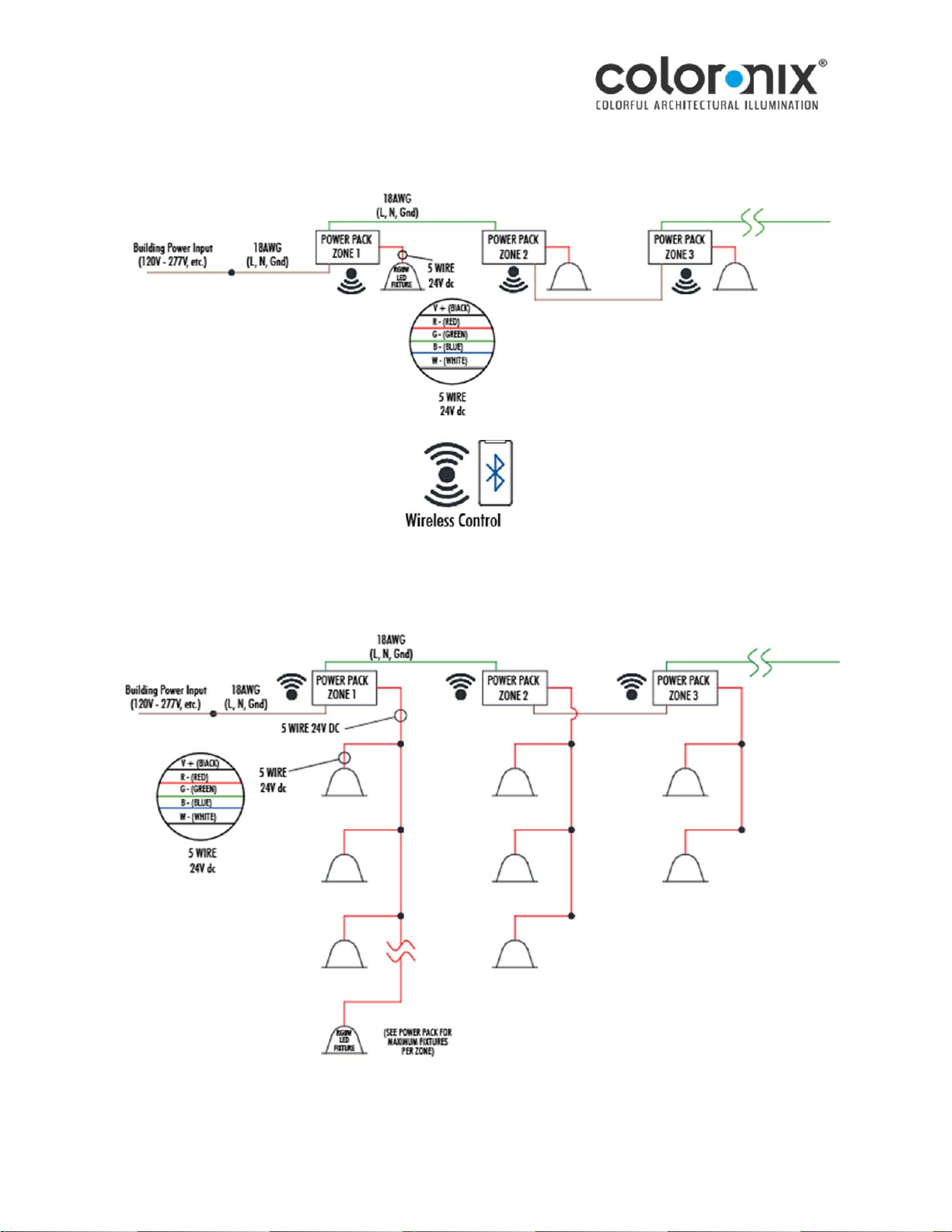
V+ (BLACK)
R - CH1 (RED)
G - CH2 (GREEN)
B - CH3 (BLUE)
W - CH4 (WHITE)
5 WIRE
(24V DC, RGBW)