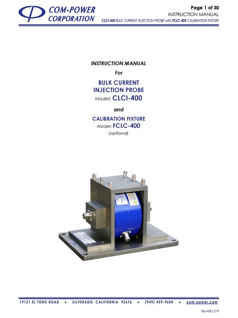
COM-power corporation CLCE-452 User manual

Page 1 of 18
INSTRUCTION MANUAL
Rev090519
INSTRUCTION MANUAL
for
RF CURRENT
PROBE
Model: CLCE-452
and
CALIBRATION
FIXTURE
Model: FCLCE-452
(optional)

Page 4 of 18
INSTRUCTION MANUAL
S E C T I O N 1 - I N T R O D U C T I O N
Rev090519
This manual includes description of product features, typical electrical performance
parameters, product specifications and instructions for use. Also included are important
safety precautions, warranty and maintenance information.
The test procedures and guidance provided herein is for general guidance and is correct
based on our understanding of the current, relevant standards at the time that this manual
was written. However, the information may become dated or may be inappropriate for
some applications.
The user is cautioned to refer and adhere to the appropriate standards, rules, procedures,
practices, and/or relevant interpretations thereof for your application in order to ensure
proper application of the test.
Information contained in this manual is the property of Com-Power Corporation. It is issued
with the understanding that the material may not be reproduced or copied without the
express written permission of Com-Power.

Page 6 of 18
INSTRUCTION MANUAL
S E C T I O N 3 -P RO D UC T I N F O RM A T IO N
Rev090519
If shipping damage to the product or any of the accessories is suspected, or if the
package contents are not complete, contact Com-Power or your Com-Power
distributor.
Please check the contents of the shipment against the package inventory in
section 3.2 to ensure that you have received all applicable items.
STANDARD ITEMS:
✓CLCE-452 RF Current Probe
✓Calibration Certificate and Associated Data
OTIONAL ITEMS:
✓FCLCE-452 Calibration Fixture

Page 7 of 18
INSTRUCTION MANUAL
S E C T I O N 3 -P RO D UC T I N F O RM A T IO N
Rev090519
The hazard symbols appearing on the product exterior are defined below.
The yellow triangle with an exclamation mark indicates the presence of
important operating and/or maintenance (servicing) instructions in the
literature accompanying the product.
The following warnings/caution statements must be adhered to in order to
ensure safe operation of the product.
CAUTION:
Hazardous Voltages present during operation. Do not handle probe
while test is in progress.
The following safety instructions have been included in compliance with
safety standard regulations. Please read them carefully.
•READ AND RETAIN INSTRUCTIONS - Read all safety and operating instructions
before operating the instrument. Retain all instructions for future reference.
•HEED WARNINGS - Adhere to all warnings on the instrument and operating
instructions.
•FOLLOW INSTRUCTIONS - Follow all operating and use instructions.
•WATER AND MOISTURE - Do not use the instrument near water.
•HEAT - The instrument should be situated away from heat sources such as heat
registers or other instruments which produce heat.
•CLEANING –Clean the instrument outside surfaces of the device with a soft, lint-
free cloth. If necessary, a mild detergent may be used.
•NON-USE PERIODS - Unplug the power cords of the instrument when it will be left
unused for a long period of time.
•OBJECT AND LIQUID ENTRY - Take care that objects do not fall into the instruments
and that liquids are not spilled into the enclosure through openings.
•DEFECTS AND ABNORMAL STRESS - Whenever it is likely that the normal operation
has been impaired, make the equipment inoperable and secure it against further
operation.
•SITTING OR CLIMBING - Do not sit or climb upon the instrument or use it as a step
or ladder.
•ENVIRONMENTAL CONDITIONS -This equipment is designed for indoor use.
Ambient temperature range during operation should be between 5° C to 40° C.
•STORAGE AND PACKAGING - The device should only be stored at a temperature
between –25 and +70 °C. During extended periods of storage, protect the device
from dust accumulation. The original packaging should be used if the device is
transported or shipped again. If the original packaging is no longer available, the
device should be packed carefully to prevent mechanical damage.

Page 8 of 18
INSTRUCTION MANUAL
S E C T I O N 3 -P RO D UC T I N F O RM A T IO N
Rev090519
Input/Output Port
This is the probe’s output port. It is fitted with an N-type (female) coaxial connector.
Spring-loaded Clasps
These two (2) clasps, when secured over their respective brackets, lock the clamp into its
closed position
Clasp Brackets
These two (2) brackets anchor the respective clasps in order to lock the clamp into its closed
position.
Clamp Window
This clamp window is the aperture in the center of the clamp through which the wire(s),
cable(s) or cable bundle(s) to be tested are passed through.

Page 9 of 18
INSTRUCTION MANUAL
S E C T I O N 3 -P RO D UC T I N F O RM A T IO N
Rev090519
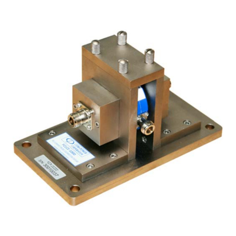
Fixture Opening
The CLCE-452 is installed within this opening so that the center conductor rod of the fixture
passes through the approximate center of the probe aperture.
Center Conductor Rod
This is the fixture’s center conductor.
Calibration Fixture Coaxial Ports
These are female N-type coaxial connectors providing input/output connections to the
fixture.
Thumb Screws for Removable Top Plate
These (4) screws secure the fixture’s top plate to the fixture assembly.
Removable Top Plate of Fixture
In order to install/remove the clamp into/from the calibration fixture, the top plate must be
removed by removing the six (6) thumb screws. The top cover and thumb screws must be
replaced prior to the performance of tests.
Teflon Spacers
These spacers help in centering the clamp within the fixture; and thereby aligning the center
conductor through the center of the probe window.

Page 10 of 18
INSTRUCTION MANUAL
S E C T I O N 3 -P RO D UC T I N F O RM A T IO N
Rev090519
Product
RF Current Probe
Model
CLCE-452
Frequency Range
10 kHz to 400 MHz
Transfer Impedance
0.25 to 3 ohms (-12 to 8 dBΩ)
Standard(s)
MIL-STD 461, RTCA-DO-160, CISPR 22, CISPR 32, etc.
Impedance
50Ω (nominal)
Coaxial RF Connector
N-type (female)
Dimensions (H)x(W)x(D)
4.9” x 1.4” x 5.9” (125 x 36 x 150 mm)
Probe Window Diameter
2” (52 mm)
Weight
1.5 lbs. (0.68 kg)
Operating Temperature
40° F to 104° F (5° C to 40° C)
All values are typical, unless specified.
All specifications are subject to change without notice.
Product
Calibration Fixture
Model
FCLCE-452
Frequency Range
10 kHz to 400 MHz
Standard(s)
MIL-STD 461, RTCA-DO-160, CISPR 22, CISPR 32, etc.
Impedance
50Ω (nominal)
VSWR
(empty fixture –
no probe installed)
0.01-50 MHz
≤1.05 : 1
50-150 MHz
≤1.1 : 1
150-200 MHz
≤1.15 : 1
200-400 MHz
≤1.3 : 1
Coaxial RF Connectors
(2) N-type (female)
Dimensions (H)x(W)x(L)
6.7” x 6.3” x 9.1” (170 x 160 x 230 mm)
Weight (empty fixture)
7.5 lbs. (3.4 kg)
Max. Probe Diameter
5.2” (132 mm)
Min. Probe Aperture Diameter
0.94” (24 mm)
Max. Probe Width
1.57” (40 mm)
Operating Temperature
40°F to 104°F (5°C to 40°C)

Page 11 of 18
INSTRUCTION MANUAL
S E C T I O N 3 -P RO D UC T I N F O RM A T IO N
Rev090519

Page 12 of 18
INSTRUCTION MANUAL
S E C T I O N 3 -P RO D UC T I N F O RM A T IO N
Rev090519

Page 13 of 18
INSTRUCTION MANUAL
S E C T I O N 3 -P RO D UC T I N F O RM A T IO N
Rev090519

Page 14 of 18
INSTRUCTION MANUAL
S E C T I O N 4 -C AL IB R A TI O N
Rev090519
Calibration fixtures provide a means by which current probes can be calibrated to
determine the insertion loss and transfer impedance factors for the probe. Fixtures are also
used when establishing or calibrating, drive levels for conducted susceptibility tests. These
applications are discussed in more detail in the following sections.
The FCLCE-452 Fixture is specifically designed for use with the CLCE-452.
The intent of the fixture is to maintain the coaxial structure of the transmission line, while
allowing the probe to be installed around the center conductor of the coaxial line.
Illustrated in Figure 8 is the procedure to be followed for installing the CLCE-452 BCI
Probe into the FCLCE-452 Calibration Fixture.

Page 15 of 18
INSTRUCTION MANUAL
S E C T I O N 4 -C AL IB R A TI O N
Rev090519
The insertion loss of a current probe, at any given frequency, quantifies the
difference between the voltage quantity present on the center conductor
of the test fixture into which the probe is installed and the voltage quantity
present at the output connector of the probe.
To determine the insertion loss of the probe, a known voltage is applied into
one side of the calibration fixture, with the opposite side terminated into 50
ohms; while measuring the voltage present at the output of the probe. The
difference between the applied voltage and the measured voltage, at
any given frequency, is the insertion loss of the probe.
Shown in Figure 9 is the equivalent schematic circuit for the calibration. The
physical test setup showing the equipment and connections is illustrated in
Figure 10.
As measured in either of the circuits shown in Figure 9, the following
equation defines the insertion loss of the probe, at any given frequency:
NOTE: Typical Insertion Loss Values for the CLCE-452 are represented in Figure 5
(Section 3.7).

Page 16 of 18
INSTRUCTION MANUAL
S E C T I O N 4 -C AL IB R A TI O N
Rev090519
When the probe is used to measure current, the transfer impedance factors
convert the [measured] voltage quantity present at the probe’s output port
into a current quantity corresponding to the actual current through the
conductor(s) passing through the probe aperture.
The transfer impedance factors include the insertion loss of the probe, and
also perform the function of converting the measured voltage quantity into
a current quantity. Based on the assumption that the probe is connected
to a measuring instrument having a nominal input impedance of 50 ohms,
this conversion is simple Ohm’s Law:
The transfer impedance factors are determined by combining the
conversion described above with the insertion loss calibration data (Lins), as
shown below:
The transfer impedance factors can be applied in practice, as follows:

Page 17 of 18
INSTRUCTION MANUAL
S E C T I O N 5 -WA RRA N T Y
Rev090519
Com-Power warrants to its Customers that the products it manufactures will be free from
defects in materials and workmanship for a period of three (3) years. This warranty shall not
apply to:
•Transport damages during shipment from your plant.
•Damages due to poor packaging.
•Products operated outside their specifications.
•Products Improperly maintained or modified.
•Consumable items such as fuses, power cords, cables, etc.
•Normal wear
•Calibration
•Products shipped outside the United States without the prior knowlege of Com-
Power.
In addition, Com-Power shall not be obliged to provide service under this warranty to
repair damage resulting from attempts to install, repair, service or modify the instrument by
personnel other than Com-Power service representatives.
Under no circumstances does Com-Power recognize or assume liability for any loss,
damage or expense arising, either directly or indirectly, from the use or handling of this
product, or any inability to use this product separately or in combination with any other
equipment.
When requesting warranty services, it is recommended that the original packaging
material be used for shipping. Damage due to improper packaging will void warranty.
In the case of repair or complaint, Please visit our website www.com-power.com and fill
out the service request form (http://com-power.com/repairservicereq.asp). Our technical
assistance personnel will contact you with an RMA number. The RMA number should be
displayed in a prominent location on the packaging and on the product, along with a
description of the problem, and your contact information.

Page 18 of 18
INSTRUCTION MANUAL
S E C T I O N 6 -MAI N T E N ANC E
Rev090519
This product contains no user serviceable parts. If the unit does not operate or needs
calibration, please contact Com-Power Corporation. Any modifications or repairs
performed on the unit by someone other than an authorized factory trained technician
will void warranty.
The exterior surface may be cleaned with mild detergent and then be wiped with a dry,
clean, lint-free cloth. Use care to avoid liquids or other foreign objects entering the chassis.
This manual suits for next models
1
Table of contents
Other COM-power corporation Measuring Instrument manuals