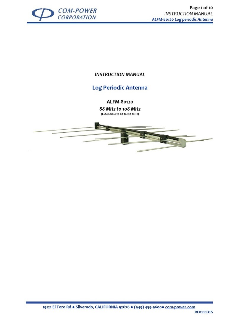
Com-Power AD-100 User manual

TUNED
DIPOLE ANTENNA
MODEL AD-100

WARRANTY
All equipment manufactured by Com-Power Corporation is warranted against defects in material
and workmanship for a period of two years from the date of shipment. Com-Power Corporation
will repair or replace any defective item or material if notified within the warranty period.
You will not be charged for warranty service performed at our factory. You must, however, pre-
pay inbound shipping costs and have a return authorization.
This warranty does not apply to:
a) products damaged during shipment from your plant or ours.
b) improperly installed products.
c) products operated outside their specifications.
d) improperly maintained products.
e) products which have been modified.
f) normal wear of material.
g) calibration.
Any warranties or guarantees, whether expressed or implied, that are not specified set forth
herein, will not be considered applicable to any equipment sold or otherwise furnished by Com-
Power Corporation. Under no circumstances does Com-Power Corporation recognize or assume
any liability for any loss, damage or expense arising either directly or indirectly from the use or
handling of products manufactured by Com-Power Corporation, or any inability to use them sepa-
rately or in combination with other equipment or material.
The warranty is void if items are shipped outside the United States, without prior approval of
Com-Power Corporation.
Warranty Limitations
The above warranty shall not apply to defects resulting from improper or inadequate maintenance
by the buyer, unauthorized modification or misuse, operation exceeding specifications, or improp-
er site preparation.

AD-100 Dipole Antenna
About this Manual
This manual provides instructions for setting up and using the Tuned Di-
pole Antenna model AD-100.
Information contained in this manual is the property of Com-Power Corpo-
ration. It is issued with the understanding that none of this material may be
reproduced or copied without written permission from Com-Power.
If you encounter problems while using the Model AD-100 Dipole antenna, con-
tact Com-Power Corporation at (949) 459-9600.
If You Need
Assistance
i

AD-100 Dipole Antenna
Contents
ii
List of Figures
Section Page
1 General Information..........................................................................1-1
1.1 Introduction..............................................................................................1-1
1.2 General Description.................................................................................1-1
1.3 Equipment Specifications.........................................................................1-1
1.4 Equipment, Accessories, and Documents Supplied................................. 1-1
2 Operating Procedures........................................................................2-1
2.0 Introduction..............................................................................................2-1
2.1 Setup ........................................................................................................2-1
.
3 Theory of Operation..........................................................................3-1
3.0 Overview..................................................................................................3-1
3.1 Theory of Operation.................................................................................3-1
1.1 Antenna Factors.......................................................................................1-3
1.2 Balun Loss ...............................................................................................1-3
1.1 Equipment Specifications.........................................................................1-2
2.1 Element type & collapsed length.............................................................2-1
3.1 Dipole typical tuned lengths, factors & balun loss..................................3-2
List of Tables

AD-100 Dipole Antenna
General Information 1
This section includes the following:
a) Introduction
b) General Description
c) Specifications
d) Equipment Supplied
1-1
1.1 Introduction
This section contains general description of the Model AD-100 dipole an-
tenna. This section also contains general performance and technical infor-
mation about the antenna.
1.2 General Description
The Model AD-100 dipole is a the standard antenna for EMC measure-
ments, site calibration and as a reference antenna for calibrating other
antennas over the frequency range of 30 to 1000 MHz.
1.3 Equipment Specifications
The Table 1-1 list the characteristics of the Model AD-100 dipole antenna.
1.4 Equipment, Accessories, and Documents Supplied
a) Four antenna baluns
b) Two pairs of fixed extension elements
c) Two pairs of collapsible extension elements
d) User's guide, Typical antenna factors
e) Individual calibration, upon request
f) Carrying case

AD-100 Dipole Antenna
1-2
Table 1-1. Equipment Specifications
Model:Dipole Antenna model AD-100
Frequency range: 30 MHz -1000 MHz Overall
Balun1 (DB-1) 30 MHz - 65 MHz
Balun 2 (DB-2) 65 MHz - 180 MHz
Balun 3 (DB-3) 180 MHz - 400 MHz
Balun 4 (DB-4) 400 MHz - 1000 MHz
Impedance: 50 Ohm
Connector Type: BNC
Weight: 18 lb. (Max)
Length: 17.5 feet maximum

AD-100 Dipole Antenna
1-3
Figure 1.1 Antenna Factors for Tuned Dipole Antenna
Figure 1.2 Typical Balun Loss

AD-100 Dipole Antenna
This section explains the following:
a) Introduction
b) Setup
Operating Procedure 22-1
2.0 Introduction
This section describes antenna setup for use.
2.1 Setup
2.1.1 Setting up and using the antenna.
Tuned dipole antennas operate over the frequency range of 30 MHz to 1000
MHz. There are four baluns to cover the entire frequency range. Each balun
has a specific frequency range. It is possible to extend the element length above
and below the specified frequency range of each balun. To prevent errors in
measurement, the element lengths should not be adjusted beyond frequency range
of each balun. Use the appropriate balun and elements for the frequency to be
measured.
Table 3.1 gives tuning lengths at selected frequencies for each balun. The tuning
length is measured from the center of the balun head. The collapsed length of
each of the element set is given in table 2.1. The lowest frequency balun DB-1
requires the use of two fixed elements and the longer (II) collapsible elements
on each side of the balun up to 45 MHz. Beyond 45 MHz, the DB-1 balun uses
one fixed length element and collapsible element (II) on each side. The DB-2
balun uses the longer collapsible elements (II) up to 125 MHz and the two
shorter collapsible elements (III) beyond it. The DB-3 balun uses only the shorter
collapsible elements (III). The DB-4 balun elements are already inserted and
fixed. Table 2.1, Tunable dipole antenna elements
Element Type Length (in.)
I Fixed 27.5
II Collapsible 8.5
III Collapsible 4.25

AD-100 Dipole Antenna
2.1.2 Setup for receiving signals
The Model AD-100 dipole antenna can be used to measure EMI from an equip-
ment under test (EUT). The antenna is mounted on either an antenna mast (such
Model AM-400) or an antenna tripod. The coax cable is used to connect the
antenna to the a measuring instrument. If a long cable is used, cable loss must be
measured and used in calculating the field strength.
2-2

AD-100 Dipole Antenna
Theory of Operation 3
This chapter explains the following:
a) Overview
b) Theory of Operation
c) Functional Block Diagram
3-1
3.0 Overview
This section describes the theory of operation of AD-100 DipoleAntenna.
3.1 Theory of Operation
The tuned dipoles are standard antennas used for calibrating Open Area Test Sites
(OATS), EMC measurement and as a reference antenna for calibrating other antennas.
These antennas are constructed according to ANSI standard C63.5 requirements.
For site attenuation measurement for the range of 30 MHz 1000 MHz, ANSI C63.5
recommends to using half wave tuned dipoles. Broadband antennas such as biconical
and log periodic antennas can also be used for site attenuation measurements. However,
use of dipole antennas are preferred because they are precise and reduce measurement
uncertainty. The broadband antennas are desirable for EMC testing because they do not
have be tuned to each frequency before making the measurement. To tune the dipole, the
wavelength of the frequency that is being measured must be calculated. The elements of
the dipole must be then adjusted to the half wavelength for that frequency before taking
measurements.
The wavelength for any frequency F the equation: Wavelength = C / Frequency in MHz
where C is the velocity of light, 3 x 10⁸meters /sec.
Using this formula the wavelength of 30 MHz is 3 x 10⁸m/sec divided by 30 x 106 Hz or
300/30 = 10 meter. Therefore, half wavelength is 10/2= 5 meters. This is the total dipole
length tip to tip. Since the balun has two sides, the elements of on both sides of the balun
head must be adjusted quarter wave length. That is 10/4 = 2.5 meters per side measured
from the center of the balun head.
It must be noted however, that these calculations are theoretical. The tuned dipole is
typically 4% smaller than this theoretical length. Table 3.1 lists the typical quarter
wavelength for adjusting the tuned dipole elements.

AD-100 Dipole Antenna
3-2
Note: L/4 is the quarter wave length of the tunable dipole at the given frequency. This is the
length measured from the notch at the center of the antenna to each tip of the two ele-
ments. Due to the finite diameter of the elements, the optimum or tuned length of the
dipole is found to be slightly less (approx. 4%) than determined by calculations.
Balun Frequency L/4 Length Balun Loss Antenna Factor
Number MHz mm dB dB
DB-1 30 2413 0.2 -1.8
35 2080 0.2 -0.5
40 1803 0.2 0.6
45 1600 0.2 1.7
50 1438 0.2 2.5
60 1197 0.2 4.2
DB-2 70 1026 0.3 5.5
80 889 0.3 6.7
90 791 0.3 7.7
100 714 0.3 8.8
120 589 0.3 10.2
125 565 0.3 10.3
140 500 0.4 11.5
150 467 0.4 11.7
160 438 0.4 12.7
175 400 0.4 12.9
180 389 0.4 13.7
DB-3 180 389 0.4 13.7
200 352 0.4 14.6
250 283 0.4 16.6
300 235 0.4 18.1
400 175 0.5 20.8
DB-4 400 175 0.5 20.6
500 143 0.5 22.6
600 117 0.5 24.2
700 102 0.5 25.5
800 89 0.5 26.7
900 79 0.5 27.7
1000 76 0.5 28.6
Table 3.1 Dipole element lengths, typical factors, typical balun loss
Table of contents
Other Com-Power Antenna manuals
Popular Antenna manuals by other brands

Avocent
Avocent Emerge HGA51G-DIR30 Quick installation guide

BAS
BAS OMNI Digital BAS-1118 Quick user guide

Light Beam Antenna
Light Beam Antenna MaxRange Series Assembly instructions

Atomic
Atomic ANTENNAE CHANDELIER installation instructions

Ubiquiti
Ubiquiti airFiber X quick start guide

HME
HME EC20 installation instructions