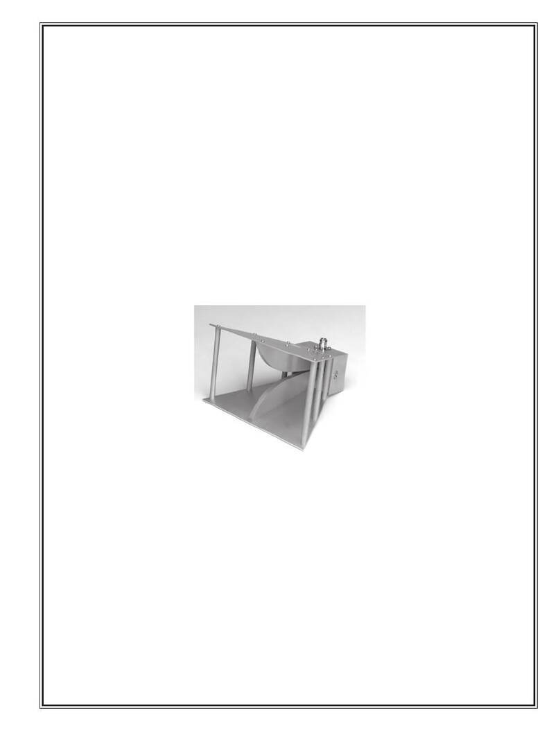
Com-Power ALC-100 User manual

LOG PERIODIC ANTENNA
300 - 1000 MHz
MODEL ALC-100
rev: 120103

WARRANTY
All equipment manufactured by Com-Power Corporation is warranted against defects in material
and workmanship for a period of two (2) years from the date of shipment. Com-Power Corpora-
tion will repair or replace any defective item or material if notified within the warranty period.
You will not be charged for warranty service performed at our factory. You must, however, pre-
pay inbound shipping costs and have a return authorization.
This warranty does not apply to:
a) products damaged during shipment from your plant or ours.
b) improperly installed products.
c) products operated outside their specifications.
d) improperly maintained products.
e) products which have been modified.
f) normal wear of material.
g) calibration.
Any warranties or guarantees, whether expressed or implied, that are not specified set forth
herein, will not be considered applicable to any equipment sold or otherwise furnished by Com-
Power Corporation. Under no circumstances does Com-Power Corporation recognize or assume
any liability for any loss, damage or expense arising either directly or indirectly from the use or
handling of products manufactured by Com-Power Corporation, or any inability to use them sepa-
rately or in combination with other equipment or material.
The warranty is void if items are shipped outside the United States, without prior approval of
Com-Power Corporation.
Warranty Limitations
The above warranty shall not apply to defects resulting from improper or inadequate maintenance
by the buyer, unauthorized modification or misuse, operation exceeding specifications, or improp-
er site preparation.

ALP-100 Log Periodic Antenna
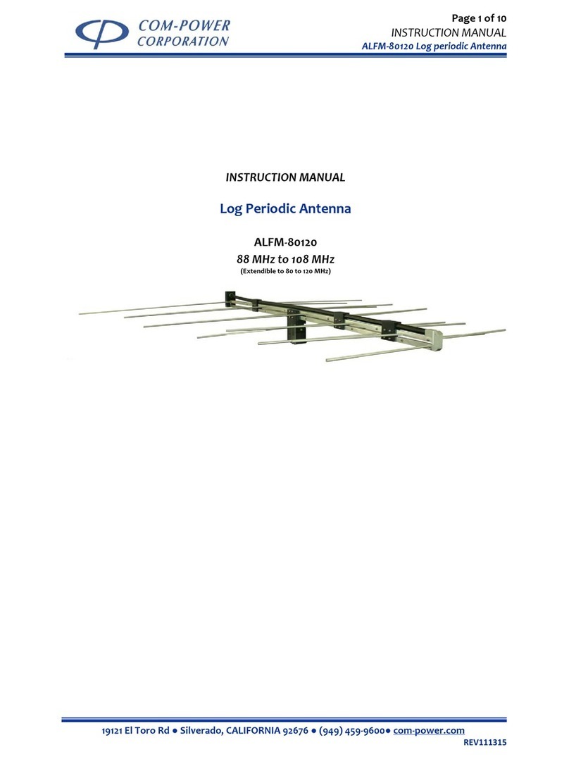
The modelALC-100 Log Periodic antenna were designed for use in an EMI labora-
tory to measure and / or generate electric (E) field strength.
Test Operator and Test Location:
The Model ALC-100 antenna should be operated by trained personnel in the
field of EMC for the purpose of generating electromagnetic fields. The Test lo-
cation should be selected to avoid interference to other equipment and exposure
of personnel to high electromagnetic fields.
Maintenance and Service:
There are no user serviceable parts inside the balun. Do not remove the instrument
cover. Com-Power provides calibration service for all equipment sold. Call the
factory if calibration or other service is required.
SAFETY PRECAUTIONS

ALP-100 Log Periodic Antenna
About this Manual
This manual provides instructions for testing and using the Log Periodic
Antenna model ALC-100.
Information contained in this manual is the property of Com-Power Cor-
poration. It is issued with the understanding that none of this material may
be reproduced or copied without written permission from Com-Power.
If you encounter problems while using the Model ALC-100, contact Com-Power
Corporation at (714) 528-8800.
If You Need
Assistance
iv

ALP-100 Log Periodic Antenna
Contents
v
List of Figures
Section Page
1 General Information..........................................................................1-1
1.1 Introduction..............................................................................................1-1
1.2 General Description.................................................................................1-1
1.3 Equipment Specifications.........................................................................1-1
1.4 Equipment, Accessories, and Documents Supplied.................................1-3
2 Connecting Procedures......................................................................2-1
2.0 Introduction..............................................................................................2-1
2.1 Antenna Setup..........................................................................................2-1
.
3 Theory of Operation..........................................................................3-1
3.0 Overview..................................................................................................3-1
3.1 Theory of Operation.................................................................................3-1
1.1 Log Periodic Antenna w/ tripod (picture)................................................1-2
1.2 Antenna Factors (typical).........................................................................1-5
1.1 Equipment Specifications.........................................................................1-4
List of Tables

ALP-100 Log Periodic Antenna
General Information 1
This section includes the following:
a) Introduction
b) General Description
c) Specifications
d) Equipment Supplied
1-1
1.1 Introduction
This section contains general description of the Log Periodic Antenna
Model ALC-100. This section also contains general performance, back-
ground information and technical information about the antennas.
1.2 General Description
The Model ALC-100 Log Periodic antennna was specifically designed
for radiated EMI measurement over a wide frequency range. This antenna
was designed to receive radiated EMI signals or transmit signals during
susceptiblity testing for various agency specifications.
The Log Periodic Antenna is a broadband transducer which converts
Electric field strength in dBuV/m to Volts that can be displayed on a
spectrum analyzer or EMI meter.
Further information on the Log Periodic Antenna is given in Section 3.
1.3 Equipment Specifications
The functional and operational characteristics of the and ALC-100 Log
Periodic antenna are listed in Table 1.1

ALP-100 Log Periodic Antenna
1-2
Figure 1.1 ALC-100 Log Periodic Antenna

ALP-100 Log Periodic Antenna
1-3
1.4 Equipment, Accessories, and Documents Supplied
Equipment, accessories, and documents supplied with the ALC-100 Log
Periodic Antennas are as follows:
a) One (1) Log Periodic Antenna
c) User's Guide
d) Calibration information

ALP-100 Log Periodic Antenna
1-4
Model: ALC-100
Frequency Range: 300 - 1000 MHz
VSWR (typ.) 1.2: :1
Impedance: 50 ohms (nominal)
Power Handling: 500 Watts CW
Connector: N (f)
Weight: 4.5 lbs.
Mounting: Center Pivoting joint for Hori-
zontal . / Vertical polarization.
Dimensions:
Length 30 inches
Width 30 inches
Table 1.1 Equipment Specifications

ALP-100 Log Periodic Antenna
Figure 1.2 - Typical Antenna Factors for ALC-100 Log Periodic Antenna
1-5

ALP-100 Log Periodic Antenna
This section explains the following:
a) Introduction
b) Setup
Setup Procedure 22-1
2.0 Introduction
This section describes antenna setup and mounting for EMI measurement.
2.1 Antenna Setup
2.1.1 Connecting
The and Model ALC-100 Log Periodic Antennas have N type (f) connectors. The
same connector is used for both signal input and output.
2.1.2 Antenna setup for receiving signals
The or Model ALC-100 antenna can be used to measure EMI from an equipment
under test (EUT). The antenna is mounted on either an antenna mast (Model AM-
400) or an antenna tripod. A cable is used to connect the antenna to the a measu-
reing instrument. If a long cable is used, cable loss must be measured and used in
calculating the field strength.
2.1.3 Antenna setup for transmitting signals
The Model ALC-100 antenna can be used to receive and transmit signals. The an-
tenna is mounted on either on an antenna mast (Model AM-400 antenna mast ) or
antenna tripod (Model AT-100). To transmit signals, the antenna is connected to a
signal generator and power amplifier. The Model ALC-100 Log Periodic Antenna
can transmit up to 500 Watts continious power. The field generated by the antenna
can be measured by using a field strength meter.
2.1.3 Test location

ALP-100 Log Periodic Antenna
The Log Periodic Antenna must be mounted and placed in area away from other
conductive objects or materials when in use. Large conductive building, struc-
tures and electrical cables, can reflect emissions of the equipment under test,
causing errors in the test data. In addition, care should be taken to keep measuring
intruments and test personnel away from the test area to avoid interference to the
test, and exposure of test personnel to electromagnetic fields.
2-2

ALP-100 Log Periodic Antenna
Theory of Operation 3
This chapter explains the following:
a) Overview
b) Theory of Operation
Functional Block Diagram
3-1
3.0 OverviewThis section describes the theory of operation of the ALC-100 Log Peri-
odic Antenna.
3.1 Theory of Operation
Broadband antennas allow measurement of signals over a wide frequency
range. These antennas do not require any tuning or balun switching
during measurement. It is very useful for sweep measurement over the
frequency range of operation. Model ALC-100 Log Periodic Antenna is
a broadband antenna that operate in the frequency range of 300 MHz to
1000 MHz.
antenna is a receive only antenna. It cannot transmit signals. However,
Model ALC-100 antenna can both receive and transmit signals over the
frequency range of operation. Model ALC-100 antennas are used for
susceptibility and emissions testing in EMC Laboratories.
Before the Log Periodic Antennas are used for measurement they have to
be calibrated. Typically antenna calibration is performed in an open field
test site( OATS). During calibration a known field strength (dBuV/m) is
generated around the antenna at each frequency (300 -1000 MHz). The
difference between field strength (dBuV) received by the antenna and
known field strength generated ( dBuV) is the antenna factor (dB) for that
frequency. During EMC testing the antenna factor for the frequency of
interest is added back to reading on the EMI meter or spectrum analyzer
to measure field strength.
dBuV/m (field strength) = dBuV (output measured) + Antenna Factor
Table of contents
Other Com-Power Antenna manuals