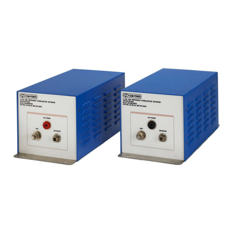
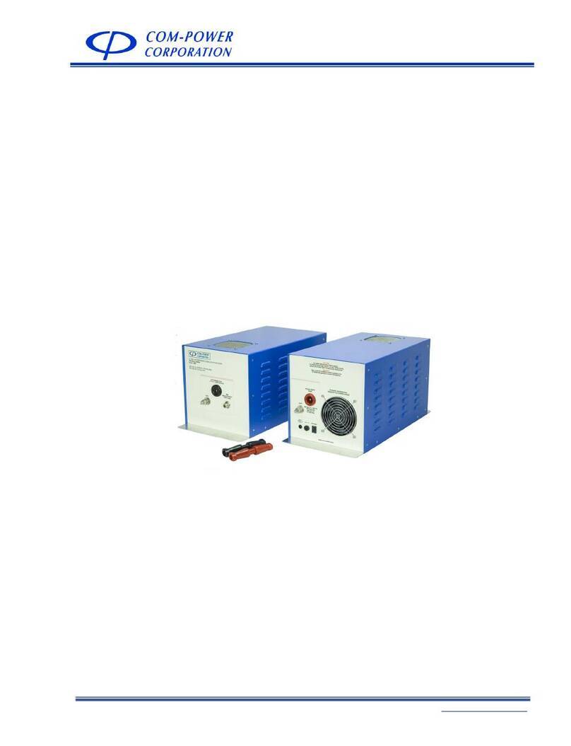
Com-Power ISN T8 User manual

Page 1 of 24
INSTRUCTION MANUAL
ISN T8 IMPEDANCE STABILIZATION NETWORK (ISN)
19121 El Toro Rd ●Silverado, California 92676 ●(949) 459-9600 ●com-power.com
REV080515
INSTRUCTION MANUAL
for
IMPEDANCE STABILIZATION
NETWORK (ISN)
Model: ISN T8
150 kHz to 30 MHz

Page 2 of 24
INSTRUCTION MANUAL
ISN T8 IMPEDANCE STABILIZATION NETWORK (ISN)
19121 El Toro Rd ●Silverado, California 92676 ●(949) 459-9600 ●com-power.com
REV080515
Table of Contents
1.0 Introduction........................................................................................................................... 4
2.0 ProductInformation ..............................................................................................................5
2.1 Overview ..................................................................................................................................... 5
2.2 StandardISNT8Items(included).............................................................................................. 5
2.3 AdditionalISNT8TestAccessories(optional).......................................................................... 5
2.4 ISNCalibrationKit....................................................................................................................... 6
2.5 OtherequipmentavailablefromCom‐Power........................................................................... 7
3.0 ProductSpecifications .......................................................................................................... 8
4.0 ProductImplementation ...................................................................................................... 9
4.1 ProductApplication.................................................................................................................... 9
4.1.1 WhencantheISNT8beused?...................................................................................................9
4.1.2 HowdoIchoosewhichLCLAdaptertouse?............................................................................ 9
4.1.3 WhatisLCL? ...............................................................................................................................10
4.2 ProductConnectionDetails ...................................................................................................... 11
Figure1–Equipmentsetupforstandardpinarrangements ..................................................... 11
Figure2–Equipmentsetupfornon‐standardpinarrangements.............................................. 11
4.2.1 ConnectorPin‐outs.................................................................................................................... 11
Figure3–ISNT8ConnectorPinArrangements/PairDesignations ............................................ 11
Figure4–RJ45LCLAdapterPinArrangements .........................................................................12
Figure5–RJ45ConnectingAdapterPinArrangements.............................................................12
Figure6–RJ11LCLAdapterPinArrangements ..........................................................................12
Figure7–RJ11ConnectingAdapterPinArrangements..............................................................12
Figure8–(8)1mmbananajackLCLAdapterPinArrangements...............................................12
Figure9–(8)1mmbananajackConnectingAdapterPinArrangements ..................................12
4.2.2 RJ45ConnectorWiring–Commonethernetcables ...............................................................13
Figure10–StandardPatchCable–ConnectorWiringDiagram ................................................13
Figure11–10/100Mb/sCross‐overCable–ConnectorWiringDiagram......................................13
Figure12–1Gb/sCross‐overCable–ConnectorWiringDiagram...............................................13
4.3 TestSetupDetails......................................................................................................................14
Figure13–AcceptableEquipmentArrangementsforTestSetup ............................................ 14
4.4 Measurement ............................................................................................................................15
4.4.1 WhatTypeofCoaxialCablingShouldBeUsedwiththeISNT8?............................................15
4.4.2 UseofAttenuatororTransientLimiterforInputProtection .................................................15
4.4.3 CorrectionFactors.....................................................................................................................17

Page 3 of 24
INSTRUCTION MANUAL
ISN T8 IMPEDANCE STABILIZATION NETWORK (ISN)
19121 El Toro Rd ●Silverado, California 92676 ●(949) 459-9600 ●com-power.com
REV080515
5.0ImportantSafetyPrecautions .............................................................................................18
5.1 Maintenance ..............................................................................................................................18
5.2 EnvironmentalConditions.........................................................................................................18
6.0Warranty ..............................................................................................................................19
7.0 ISNTheory ............................................................................................................................20
Figure14–CircuitConceptofISNT8(CISPR22,FigureD.3) ......................................................20
8.0 TypicalPerformanceData ................................................................................................... 21
Figure15–TypicalAsymmetricImpedanceCharacteristics.......................................................21
Figure16–TypicalAsymmetricPhaseCharacteristics ...............................................................21
Figure17–TypicalLongitudinalConversionLoss(LCL)Characteristics(Cat.3) ........................ 22
Figure18–TypicalLongitudinalConversionLoss(LCL)Characteristics(Cat.5)........................ 22
Figure19–TypicalVoltageDivisionFactor(VDF)Characteristics............................................. 23
Figure20–TypicalIsolationCharacteristics.............................................................................. 23
Figure21–TypicalSymmetricInsertionLossCharacteristics.................................................... 24

Page 4 of 24
INSTRUCTION MANUAL
ISN T8 IMPEDANCE STABILIZATION NETWORK (ISN)
19121 El Toro Rd ●Silverado, California 92676 ●(949) 459-9600 ●com-power.com
REV080515
1.0 Introduction
This manual includes product specifications, safety precautions, product
maintenance and warranty information. It also includes instructions for
connection of the ISN and associated accessories to the Equipment Under Test
(EUT) and Ancilliary Equipment (AE) and testing guidelines.
Information contained in this manual is the property of Com-Power Corporation.
It is issued with the understanding that none of the material may be reproduced
or copied without permission from Com-Power.

Page 5 of 24
INSTRUCTION MANUAL
ISN T8 IMPEDANCE STABILIZATION NETWORK (ISN)
19121 El Toro Rd ●Silverado, California 92676 ●(949) 459-9600 ●com-power.com
REV080515
2.0 Product Information
2.1 Overview
The ISN T8 Impedance Stabilization Network (ISN) is designed based on the
circuit illustrated in Figure D.3 of CISPR 22. It is used for common mode
conducted disturbance measurements on telecommunication ports
intended for connection to Cat. 3 or Cat. 5 networks utilizing one, two,
three or four unshielded, balanced, twisted pairs.
2.2 Standard ISN T8 Items (included)
9RJ45 Adapter Set (wiring arrangement per ANSI/TIA/EIA-568-B)
Adapter Type Interface
Connector(s)
Wiring
Diagram Part Number
Cat. 3 LCL Adapter RJ45 Figure 4 ISN-LCL-CAT3-T8-RJ45
Cat. 5 LCL Adapter RJ45 Figure 4 ISN-LCL-CAT5-T8-RJ45
Connecting Adapter RJ45 Figure 5 ISN-ADA-T8-RJ45
9Instruction Manual
9Calibration data and Certificate traceable to NIST
(ISO 17025 accredited calibration also available)
2.3 Additional ISN T8 Test Accessories (optional)
9RJ11 Adapter Set (wiring arrangement per ANSI/TIA/EIA-568-B)
Adapter Type Interface
Connector(s)
Wiring
Diagram Part Number
Cat. 3 LCL Adapter RJ11 Figure 6 ISN-LCL-CAT3-T8-RJ11
Cat. 5 LCL Adapter RJ11 Figure 6 ISN-LCL-CAT5-T8-RJ11
Connecting Adapter RJ11 Figure 7 ISN-ADA-T8-RJ11
9(8x) 1mm Banana Jack Adapter Set (for non-standard pin arrangements)
Adapter Type Interface
Connector(s)
Wiring
Diagram Part Number
Cat. 3 LCL Adapter (8x)1mm banana Figure 8 ISN-LCL-CAT3-T8-1mm
Cat. 5 LCL Adapter (8x)1mm banana Figure 8 ISN-LCL-CAT5-T8-1mm
Connecting Adapter (8x)1mm banana Figure 9 ISN-ADA-T8-1mm
(4) UTP Adapter Cable RJ45 ISN-T8-CBL-1mm-RJ45
(2) Pair Adapter Cable RJ11 ISN-T8-CBL-1mm-RJ11

Page 6 of 24
INSTRUCTION MANUAL
ISN T8 IMPEDANCE STABILIZATION NETWORK (ISN)
19121 El Toro Rd ●Silverado, California 92676 ●(949) 459-9600 ●com-power.com
REV080515
2.4 ISN Calibration Kit
Com-Power’s ISN Calibration Kit provides all of the needed calibration
adapters/accessories. Also provided are detailed, step-by-step
instructions to intuitively guide you through the calibration of the following
electrical parameters:
9Impedance - [asymmetric - common-mode]
9Phase [asymmetric - common-mode]
9Voltage Division Factor (VDF)
9Decoupling Attenuation (Isolation)
9Longitudinal Conversion Loss (LCL)
Generally, any of the folliowing combinations of test & measurement
equipment may be employed for the calibration:
Network Analyzer with [2-port] S-parameter capabilities
Spectrum Analyzer or EMI Receiver with Tracking Generator,
and Impedance Analyzer (or equivalent)
Spectrum Analyzer or EMI Receiver, Synthesized Signal Generator,
and Impedance Analyzer (or equivalent)
Gain-Phase Analyzer with Impedance measurement capabilities
The ISN calibration kit is available with the following items:
Part Description Part Number
Balance Transformer (LCL Probe) ISN-BT-T248
Balance Transformer Calibration Load Block ISN-CLB-BT
(2x) 10 dB Attenuators ATTN-10-T248
(2x) 150Ωto 50ΩAdapters ADA-515-T248
BNC Short Adapter ADA-0-BNC
BNC 50 ΩTerminator BNC-50-BNC
8 cm Twisted Pair with 1mm banana plugs ISN-CBL-1mm
(2x) RJ45 (or RJ11) Common Mode Adapter ISN-ADA-T248-RJxx
(4x) 1x100ΩPair Termination for LCL Adapter w/1mm ISN-100x1-T248-1mm
4x100ΩTermination Block for Conn. Adapter w/1mm ISN-100x4-T8-1mm
Adapters/Terminations for LCL measurement of individual pairs
Sin
gle Pair
RJ
11
or
RJ
45
Two Pairs
RJ
11
or
RJ
45
Three or Four Pairs
RJ45
Part Number for
Pair Adapter or
100ΩAE Terminator
P1
100Ω
P1 P2
100Ω
P1 P2 P3 P4
100Ω
ISN-T2-xxx-RJyy X X
ISN-T4-xxx-RJyy X X X
ISN-T8-xxx-RJyy X X X X X

Page 7 of 24
INSTRUCTION MANUAL
ISN T8 IMPEDANCE STABILIZATION NETWORK (ISN)
19121 El Toro Rd ●Silverado, California 92676 ●(949) 459-9600 ●com-power.com
REV080515
AntennasAntennaKits AbsorbingClamps Coupling/Decoupling
Networks(CDN)
CombGeneratorsCurrentProbes EmissionsTest
Systems
ConductedImmunity
TestSystems
ImpedanceStabilization
Networks(ISN)
LineImpedanceStabilization
Networks(LISN)
AntennaMasts Near‐Fiel
d
ProbeSets
PreamplifiersPowerAmplifiers
S
pectrumAnalyzers ProductSafetyTest
Equipment
TransientLimitersTurntablesAntennaTripods TelecomTest
Systems
2.5 Other equipment available from Com-Power
www.com-power.com

Page 8 of 24
INSTRUCTION MANUAL
ISN T8 IMPEDANCE STABILIZATION NETWORK (ISN)
19121 El Toro Rd ●Silverado, California 92676 ●(949) 459-9600 ●com-power.com
REV080515
3.0 Product Specifications
Technical
Frequency Range: 150 kHz to 30 MHz
Compliant Standards: CISPR 16-1-2, CISPR 22, EN 55022
ISN Type: Figure D.3 of CISPR 22 / EN 55022
Impedance/Phase (EUT Port): 150Ω±20Ω/ 0° ±20°
Longitudinal Conversion Loss
ISN T8 w/Cat. 3 LCL Adapter: 55-10*log[1+(f/5)2] dB ±3 dB 150 kHz to 30 MHz
ISN T8 w/Cat. 5 LCL Adapter: 65-10*log[1+(f/5)2] dB ±3 dB 150 kHz to 2 MHz
where: -3 dB
f = frequency in MHz +4.5 dB 2 MHz to 30 MHz
Voltage Division Factor
(EUT Port to RF Port): 10.5 dB ±1 dB
Isolation (decoupling >35 dB @ 150 kHz
(AE Port to EUT Port): >55 dB @ 1.5 MHz
(increasing linearly with logarithm of
frequency from 150 kHz to 1.5 MHz)
>55 dB, 1.5 MHz to 30 MHz
Symmetric Insertion Loss
(AE Port to EUT Port):Max: 3 dB ±0.25 dB
Symmetric Load Impedance: 100Ω
Transmission Bandwidth: >100 MHz
Electrical
Max. Current Rating: 800 mA (per line), 1.6 A (per pair)
Max. Voltage Ratings: 50 VDC / 32 VAC (line to ground @ 50/60 Hz)
Mechanical
Total Conductors / (Pairs) 8 conductors / (4 unshielded twisted pairs)
RF & I/O Connectors
ISN T8 EUT/AE Port: DB-25 (female - non-metallic D-shell)
RF Port:
Coaxial BNC (female - 50Ω)
LCL Adapters ISN Port: DB-25 (male – metallic D-shell)
EUT Port:
RJ45 Jack (also available with RJ11 or (8) 1mm banana jacks)
ISN Port: DB-25 (male – metallic D-shell)
Connecting
Adapters EUT Port: RJ45 Jack (also available with RJ11 or (8) 1mm banana jacks)
Dimensions (L x W x H)
ISN T8: 6.5” x 4.125” x 3” (16.5 cm x 10.5 cm x 7.6 cm)
LCL & Connecting Adapters: 2.2” x 2.4” x 1.6” (5.6 cm x 6.1 cm x 4.1 cm)
Weight
ISN T8: 1 lb., 1.7 oz. (502 grams)
Cat. 3 LCL Adapters: 2.1 oz. (60 grams)
Cat. 5 LCL Adapters: 2.2 oz. (62 grams)
Connecting Adapters: 2 oz. (57 grams)
Environmental
Operating Temperature: 40°F to 104°F (5°C to 40°C) - INDOOR USE ONLY -

Page 9 of 24
INSTRUCTION MANUAL
ISN T8 IMPEDANCE STABILIZATION NETWORK (ISN)
19121 El Toro Rd ●Silverado, California 92676 ●(949) 459-9600 ●com-power.com
REV080515
4.0 Product Implementation
The following sections contain useful information about your ISN T8. Guidance is
provided for; determining when use of an ISN is appropriate; how to use the ISN,
including application of correction factors. Also, detailed connection and wiring
diagrams are provided for proper connection of the Equipment Under Test (EUT)
and Accessory (or ancilliary) Equipment (AE) to the ISN.
Notwithstanding the information provided herein, the user is encouraged to refer
to the appropriate test specification and/or applicable test procedures for test
requirements, which hold precedence over any conflicting information provided
here. This information is provided for guidance purposes only, and may or may
not be appropriate for your specific test requirements, and may become
outdated or obsolete. The following information is based on a current
understanding of general test requirements, and may not be complete.
4.1 Product Application
4.1.1 When can the ISN T8 be used?
The ISN T8 is appropriate for measurements on unshielded lines
containing one, two, three or four balanced pairs, intended for
connection to Cat. 3 or Cat. 5 networks.
The user should ensure that the maximum ratings (voltage, current),
declared in Section 3 of this document, are not exceeded.
4.1.2 How do I choose which LCL Adapter to use?
The Cat. 3 LCL adapter simulates a network employing Cat. 3
compliant cabling, and the Cat. 5 LCL adapter simulates a network
employing Cat. 5 compliant cabling.
If the EUT is intended to be connected to Cat. 3 networks, then the
Cat. 3 LCL adapter should be used. If the EUT is intended to be
connected to Cat. 5 networks, then the Cat. 5 LCL adapter should
be used. If the EUT is intended to be connected to either network
category, then the test should be performed with the Cat. 3 LCL
adapter and again with the Cat. 5 adapter. The emission levels
measured using the Cat. 3 LCL adapter are likely to be slightly
higher than the emission levels measured using the Cat. 5 LCL
adapter.

Page 10 of 24
INSTRUCTION MANUAL
ISN T8 IMPEDANCE STABILIZATION NETWORK (ISN)
19121 El Toro Rd ●Silverado, California 92676 ●(949) 459-9600 ●com-power.com
REV080515
The pin arrangements of the LCL/Connecting adapters equipped
with RJ45 and RJ11 jacks [ISN-LCL-CATx-T8-RJxx] are consistent with
the respective arrangements specified in ANSI/TIA/EIA-568-B, and
are illustrated in Section 4.2.1 of the present document.
For non-standard pin arrangements, use of the following
accessories is recommended:
LCL Adapter: P/N: ISN-LCL-CATx-T8-1mm
Connecting Adapter: P/N: ISN-LCL-CATx-T8-1mm
RJ45 Wiring Adapter: P/N: ISN-T8-CBL-1mm-RJ45
RJ11 Wiring Adapter: P/N: ISN-T4-CBL-1mm-RJ11
The LCL adapter connects to the EUT port of the ISN. The network
cable to be tested connects directly to the LCL adapter.
The connecting adapter connects to the AE port of the ISN. The
network cable which is connected to the accessory equipment
connects directly to the connecting adapter. See Figures 1 and 2
in Section 4.2.
4.1.3 What is LCL?
Longitudinal Conversion Loss (LCL) is an electrical parameter by
which the state of electrical balance is guaged, as it relates to the
physical geometry and the dielectric properties of a twisted pair of
conductors. A balanced transmission line (with respect to its
surroundings) is one whose two insulated conductors are perfectly
symmetrical, in that they are physically identical to one another in
diameter, concentricity, dielectric material, and are uniformly
twisted with equal length conductors
Specifically, LCL is the ratio between the [wanted] differential
voltage magnitude and the [unwanted] common-mode voltage
magnitude. The latter refers to the voltage quantity that has been
converted from differential mode to common-mode, occurring
due to [and in direct proportion to] the quantity or state of
imbalance which exists between the twisted pair conductors in the
cable.
The LCL of an ideally balanced transmission line is infinite; and,
conversely, the LCL of an ideal unbalanced transmission line (i.e.:
coaxial) is zero. The LCL for a Cat. 6 cable is 10 dB greater (more
balanced) than that of a Cat. 5 cable, which is 10 dB greater than
that of a Cat. 3 cable.

Page 11 of 24
INSTRUCTION MANUAL
ISN T8 IMPEDANCE STABILIZATION NETWORK (ISN)
19121 El Toro Rd ●Silverado, California 92676 ●(949) 459-9600 ●com-power.com
REV080515
4.2 Product Connection Details
Figure 1 – Equipment setup for standard pin arrangements
Figure 2 – Equipment setup for non-standard pin arrangements
4.2.1 Connector Pin-outs
Figure 3 – ISN T8 Connector Pin Arrangements/Pair Designations
Equipment
UnderTest
(EUT)
Ancilliary
(accessory)
Equipment
(
AE
)
AE
EUT
Impedance
Stabilization Network
ISN Tx
RF PORT
Connecting
Adapter
ISN-ADA-Tx-RJxx
LCL Adapter
ISN-LCL-CATx
-Tx-RJxx
AE
EUT
Impedance
Stabilization Network
ISN Tx
RF PORT
Connecting
Adapter
ISN-ADA-Tx-1mm
LCL Adapter
ISN-LCL-CATx
-Tx-1mm
RJ45
Jack
RJ45
Jack
Equipment
UnderTest
(EUT)
Ancilliary
(accessory)
Equipment
(AE)
ISN T8
CONNECTOR
PIN-OUTS
Pair 1
Pair 2
Pair 3
Pair 4
21
18
19
20
7
5
6
8
Pair 3
Pair 4
Pair 1
Pair 2
18
21
20
19
6
8
7
5

Page 12 of 24
INSTRUCTION MANUAL
ISN T8 IMPEDANCE STABILIZATION NETWORK (ISN)
19121 El Toro Rd ●Silverado, California 92676 ●(949) 459-9600 ●com-power.com
REV080515
ISN-LCL-CATx-T8-RJ11
LCL ADAPTER
PIN-OUTS
19
7
6
20
RJ11
JACK
1
3
4
2
ISN-ADA-T8-RJ11
CONNECTING
ADAPTER PIN-OUTS
RJ11
JACK
20
19
6
7
1
3
4
2
ISN-LCL-CATx-T8-RJ11
LCL ADAPTER
PIN-OUTS
19
7
6
20
RJ11
JACK
1
3
4
2
ISN-ADA-T8-RJ11
CONNECTING
ADAPTER PIN-OUTS
RJ11
JACK
20
19
6
7
1
3
4
2
Figure 4 – RJ45 LCL Adapter Pin Arrangements
Figure 5 – RJ45 Connecting Adapter Pin Arrangements
Figure 6 – RJ11 LCL Adapter Pin Arrangements
Figure 7 – RJ11 Connecting Adapter Pin Arrangements
Figure 8 – (8) 1mm banana jack LCL Adapter Pin Arrangements
Figure 9 – (8) 1mm banana jack Connecting Adapter Pin Arrangements
Figure 4 – RJ45 LCL Adapter
Pin Arrangements
Figure 5 – RJ45 Connecting
Adapter
Pin Arrangements
Figure 6 – RJ11 LCL Adapter
Pin Arrangements
Figure 7 – RJ11 Connecting
Adapter
Pin Arrangements
ISN-ADA-T8-RJ45
CONNECTING
ADAPTER PIN-OUTS
18
21
20
19
6
8
7
5
RJ45
JACK
8
2
4
6
5
1
3
7
RJ45
JACK
ISN-LCL-CATx-T8-RJ45
LCL ADAPTER
PIN-OUTS
21
7
18
19
5
6
20
8
2
8
6
4
3
7
5
1

Page 13 of 24
INSTRUCTION MANUAL
ISN T8 IMPEDANCE STABILIZATION NETWORK (ISN)
19121 El Toro Rd ●Silverado, California 92676 ●(949) 459-9600 ●com-power.com
REV080515
Figure 8 – (8) 1mm banana jack
LCL Adapter
Pin Arrangements
Figure 9 – (8) 1mm banana jack
Connecting Adapter
Pin Arrangements
4.2.2 RJ45 Connector Wiring – Common ethernet cables
Figure 10 – Standard Patch Cable – Connector Wiring Diagram
Figure 11 – 10/100 Mb/s Cross-over Cable – Connector Wiring Diagram
Figure 12 – 1 Gb/s Cross-over Cable – Connector Wiring Diagram
ISN-ADA-T8-1mm
CONNECTING
ADAPTER PIN-OUTS
18
21
20
19
6
8
7
5
ISN-LCL-CATx-T8-1mm
LCL ADAPTER
PIN-OUTS
21
7
18
19
5
6
20
8

Page 14 of 24
INSTRUCTION MANUAL
ISN T8 IMPEDANCE STABILIZATION NETWORK (ISN)
19121 El Toro Rd ●Silverado, California 92676 ●(949) 459-9600 ●com-power.com
REV080515
4.3 Test Setup Details
Figure 13 – Acceptable Equipment Arrangements for Test Setup

Page 15 of 24
INSTRUCTION MANUAL
ISN T8 IMPEDANCE STABILIZATION NETWORK (ISN)
19121 El Toro Rd ●Silverado, California 92676 ●(949) 459-9600 ●com-power.com
REV080515
4.4 Measurement
This section provides essential information for using your ISN for accurate
measurements of common mode disturbance voltages from the EUT
which are present on the lines to which it is connected.
4.4.1 What Type of Coaxial Cabling Should Be Used with the ISN T8?
For EMI measurements, connections should always be made with a
high quality, coaxial cable having a nominal impedance of fifty
ohms.
Double-shielded coax, such as RG-223 (approx. Ø1/4”) or RG-214
(approx. Ø 1/2”) is recommended. These types of coax cable
feature two silver-plated copper braid shields. The silver plating
increases the life of the cable, among other advantages.
Lower quality cables have shields comprised of unplated copper or
even foil, which tend to break easily, and degrade or corrode over
time. Once the shield has been compromised, the impedance
and insertion loss can be affected, leading to measurement
inaccuracies, as well as increasing the likelyhood of picking up
ambient radio signals that can interfere with your measurements.
Good to high quality connectors should be used on the coax
cables. Lower quality connectors tend to break easily, and may
not terminate the shield properly.
If you are installing, or if you have installed, your own connectors,
make sure that the connectors are designed to fit your specific
cable dimensions. The individual diameters of the center
conductor, dielectric material, and outer conductor can vary from
cable to cable (even when the overall diameter of the cables are
the same or similar).
4.4.2 Use of Attenuator or Transient Limiter for Input Protection
It is highly recommend that an external attenuator or transient
limiter be used between the RF port of the ISN T8 and the input of
the measuring instrument for all conducted measurements.
The attenuator or transient limiter should have at least 10 dB
attenuation, and be capable of withstanding no more than about
four times the maximum input power of your measuring instrument.
Typically, measuring instruments have a maximum input of one
watt, so a four watt attenuator or transient limiter is ideal.
Using an external attenuator or transient limiter accomplishes the
following:

Page 16 of 24
INSTRUCTION MANUAL
ISN T8 IMPEDANCE STABILIZATION NETWORK (ISN)
19121 El Toro Rd ●Silverado, California 92676 ●(949) 459-9600 ●com-power.com
REV080515
9Adds a barrier of protection for the highly sensitive RF input
of your spectrum analyzer or EMI receiver, as described
below. The following assumes a 10 dB/4W attenuator or
limiter.
If a high amplitude signal is present [1W to 4W], its amplitude
will be reduced by 10 dB [0.1W to 0.4], which the instrument
is capable of withstanding.
If a higher amplitude signal is present [>4W], then the
attenuator or limiter will blow, and become an open circuit,
protecting the analyzer input from exposure to the signal.
The pervailing logic here is that it is cheaper to replace an
attenuator than to replace/repair the RF input of your
instrument.
9Provides impedance matching in order to reduce RF
reflections.
In addition to the above, a transient limiter offers the following
additional advantages when compared to the attenuator alone:
9Provides protection against incidental transients.
9Provides DC blocking protection.
Due to the nature of the ISN T8, transient or DC voltages are not
likely to be present at the RF port, and is more likely to occur due to
human error, or when performing measurements on power lines.

Page 17 of 24
INSTRUCTION MANUAL
ISN T8 IMPEDANCE STABILIZATION NETWORK (ISN)
19121 El Toro Rd ●Silverado, California 92676 ●(949) 459-9600 ●com-power.com
REV080515
4.4.3 Correction Factors
As with all ISN’s, the impedance of the ISN T8 is 150Ω. Since the
input impedance of your measuring instrument is 50Ω, it will
measure one-third of the voltage that is present at the RF port. This
is what is referred to as the Voltage Division Factor (VDF).
where:
Additionally, other nominal losses occur within the ISN and LCL
adapters, which must also be accounted for in order to accurately
correct the measured voltage levels present at the RF port of the
ISN. The voltage division factors supplied with your ISN T8 include all
such losses, ranging from 9.5 to 11.5 dB over the frequency range.
There are two sets of factors included, corresponding to the
calibration of the ISN T8 with the Cat. 3 LCL Adapter and the ISN T8
with the Cat. 5 LCL Adapter. Make sure that the appropriate set of
factors are used, depending on which LCL adapter you are using.
These frequency-specific correction factors are added to the
values measured on the spectrum analyzer or EMI receiver:
Keep in mind that if you are If you are using an external attenuator
or transient limiter, that must also be taken into account. And, if
significant, you should also correct your data for the insertion loss of
the cable you are using to connect the ISN T8 to your measuring
instrument. These are all losses, so they must be added to your
measured value.
NOTE: Some [attenuator/cable] manufacturers may report loss as a negative value. If this is
the case, they should be entered into your software, or applied into your calculations, as
absolute values for purposes of measurement correction.
-or-
=
= 3
V
(150Ω)
V
(50Ω)
VDF
(linear)
= 20 x log
= 9.5 dB
V
(150Ω)
V
(50Ω)
VDF
(dB)
V
(50
Ω
)
Voltage measured across 50Ω
Voltage measured with 50Ωinput impedance
Measured Value
=
=
=
V
(150
Ω
)
Voltage present across 150Ω
Voltage present across an ISN/CDN network
Corrected Value
=
=
=
=
V
(50Ω)
V
(150Ω)
VDF
(linear)
-or-
V
(150Ω)
=
+
VDF
(d
B)
V
(50Ω)
x
=
+
VDF
(dB)
V
(50Ω)
V
(150Ω)
+
Cable
Lo ss (dB )
External
Atten. (dB)
+

Page 18 of 24
INSTRUCTION MANUAL
ISN T8 IMPEDANCE STABILIZATION NETWORK (ISN)
19121 El Toro Rd ●Silverado, California 92676 ●(949) 459-9600 ●com-power.com
REV080515
5.0 Important Safety Precautions
The ISN must be securely fastened to the earth ground before making any connections
to external power. Proper grounding of the ISN is essensial for accurate measurements,
as well as preventing potentially high leakage currents from presenting a hazard to test
personnel. To help establish proper grounding the base of the ISN is an unpainted,
conductive plate with mounting holes which can be utilized for securely bolting it to the
ground plane.
5.1 Maintenance
There are no user serviceable parts inside the unit. User modifications to
the ISN or its accessories will void the warranty and may also invalidate
the calibration. If you feel the ISN is not functioning properly, discontinue
use and contact us for assistance. If we ask that you return the ISN for
service, you will be provided with a Return Merchandise Authorization
(RMA) number. The RMA number should be displayed in a prominent
location on the packaging and on the product.
5.2 Environmental Conditions
This equipment is designed for indoor use to be safe under the following
environmental conditions:
•Temperature: 5° C to 40° C
•Maximum relative humidity: 80%

Page 19 of 24
INSTRUCTION MANUAL
ISN T8 IMPEDANCE STABILIZATION NETWORK (ISN)
19121 El Toro Rd ●Silverado, California 92676 ●(949) 459-9600 ●com-power.com
REV080515
6.0 Warranty
Com-Power warrants to its Customers that the products it manufactures will be free
from defects in materials and workmanship for a period of three (3) years. This warranty
shall not apply to:
•Transport damages during shipment from your plant.
•Damages due to poor packaging.
•Products operated outside their specifications.
•Products Improperly maintained or modified.
•Consumable items such as fuses, power cords, cables, etc.
•Normal wear
•Calibration
•Products shipped outside the United States without the prior knowlege of Com-
Power.
In addition, Com-Power shall not be obliged to provide service under this warranty to
repair damage resulting from attempts to install, repair, service or modify the instrument
by personnel other than Com-Power service representatives.
Under no circumstances does Com-Power recognize or assume liability for any loss,
damage or expense arising, either directly or indirectly, from the use or handling of this
product, or any inability to use this product separately or in combination with any other
equipment.
When requesting warranty services, it is recommended that the original packaging
material be used for shipping. Damage due to improper packaging will void warranty.
If you feel that the product is not working as intended, or is malfunctioning, please
contact Com-Power for assistance. If the product must be returned to Com-Power, a
Return Merchandise Authorization (RMA) number will be supplied to you. The RMA
number should be displayed in a prominent location on the packaging and on the
product, along with a description of the problem, and your contact information.
.

Page 20 of 24
INSTRUCTION MANUAL
ISN T8 IMPEDANCE STABILIZATION NETWORK (ISN)
19121 El Toro Rd ●Silverado, California 92676 ●(949) 459-9600 ●com-power.com
REV080515
7.0 ISN Theory
Impedance Stabilization Networks (ISN) provide a means by which to measure common-
mode disturbance voltages (conducted emissions) on telecommunication ports. The ISN
T8 is used for measurements on unshielded telecommunication ports intended for
connection to Cat. 3 or Cat. 5 wired networks. It is suitable for cables with one, two,
three or four balanced pairs. The design of the ISN T8 is based on Figure D.3 of CISPR 22
(EN 55022).
Figure 14 – Circuit Concept of ISN T8 (CISPR 22, Figure D.3)
The basic concept of the ISN is similar to that of an LISN (Line Impedance Stabilization
Network) for disturbance voltage measurements on power lines, insofar as they both:
•connect in series with, and impose a defined impedance on, the lines under test;
thereby providing a distinct advantage over current or voltage probe
measurements, where the impedance of the lines is largely uncontrolled.
•provide isolation between the input and output ports, which:
9minimizes influence of the input impedance on the impedance of the
network.
9reduces the contribution of unwanted signals to the measurement results.
The ISN is used for measurements on lines which host various types of high-speed,
symmetric (differential-mode) communications, often operating within the same
frequency band over which the measurements are performed. It is for this reason that,
from a differential-mode perspective, the ISN should not impede the wanted signal path
[thru-put], but should impede the path to the measurement port, as the intent of the test
is not to limit the level of the wanted signals. In addition, the ISN measures all conductors
of the line simultaneously with respect to ground, thereby measuring only the common-
mode voltages, and not the differential.
In contrast, the LISN is used to measure each current carrying conductor individually, with
reference to ground, making no distinction between, and therefore measuring, both
differential and common mode voltages. In most cases, it need only pass the power
frequencies (50 or 60 Hz), far below those frequencies over which measurements are
performed.
Table of contents
Other Com-Power Network Hardware manuals