manuals.online logo
Brands
  1. Home
  2. •
  3. Brands
  4. •
  5. CommScope
  6. •
  7. Network Hardware
  8. •
  9. CommScope FDC-W8-FAT User manual

CommScope FDC-W8-FAT User manual

Fiber Drop Closure for Fiber Access Terminal
Contents 1 General
2 Sizing and product kit
information
3 Installation conditions
precautions
4 Closure preparation
5 Cable installation
6 Fiber preparation
7 Splicing and fiber storage
8 Pole mount installation
9 Wall mount installation
10 Re-entry and drop cable installation
1 General
1.1 Installation Instruction description
The installation instruction describes the necessary steps to install the FDC-W8. The installation
instruction illustrates the use on loose tube cables. If other cable types are used, please contact
the local agent for relevant accessories and instructions.
1.2 Product description
The FDC-W8-FAT is a butt type gel sealed fiber optic splicing and patching closures designed for
fiber access point applications in the telecom outside plant network. FDC-W8 FAT has 4 main
cable ports and 8 drop cable ports. Loop storage of 6m loose tubes allows 2 main cables loop
through at the same time. The closure accommodates up to 24 fusion splices (or 8 mechanical
splices), two PLC splitters and 8 SC adapters. Sealing is achieved visa built-in gel technology,
resulting in extremely convenient re-entry and re-sealing.
2 Sizing and product kit information
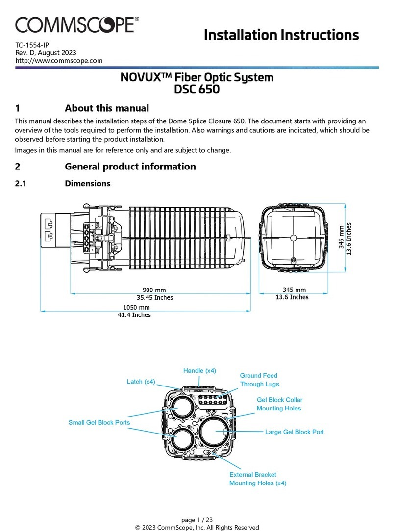
2.1 Dimensions
Main Cable diameter range 8-14 mm
Drop Cable diameter: 3mm round cable or 2 X3mm fig.8 cable
Closure outer dimensions 266 x 237 x 76.5 mm
FDC-
W
8-FAT
INSTALLATION INSTRUCTIO N
TC-2164-IP
Rev. A, May 2018
www.commScope.com
CZ2416-000 Rev B
2
2.2 Kit content
* Below listed is a standard kit, alternative kits and accessories
are available.
1. Cover and base with latch
2.
Tray
kits 1
pc
3.Splitter 1
pc
4. Cable bracket and screws 4 sets
5.
Adaptors 8
pcs
6. Transportation
tubs 4
pcs
7. Twist wrap and screw2 sets
8. Big head screw 4
pcs
9.Smouv
10. Ring tree 2
pcs
11. Dummy rod (small) 2 pcs
12. Dummy rod (8mm) &snap block 4 pcs
13. White tie wraps 12
pcs
14. Black tie wraps4
pc
15. Clean tissue 1
pc
16. Installation instruction
3 Installation conditions precautions
3.1 The closures should be installed at temperature
between -5°C and 45°C.
3.2 Follow the installation instruction steps to ensure the
performance of the closure.
3.3 It is necessary to take precautions and keep the
working space clean to protect the closure sealing
materials and splices.
4 Closures preparation
4.1 Open the closures by unscrew the all screws on the
closure cover, as shown in left below. Then
unlatched two sides, as shown, in right below.
4.2 Open the cover. Then open the tray by press-in the
tray latch, as shown.
4.3 Unscrew the upper clamps where you will install the
cable.
Note: Prefer to use manual screwdriver or electric
screwdriver in low speed.
3
4.4 Take out upper clamp and the dummy rods.
4.5 Separate the dummy rod and the blocking ring, as
shown
4.6 According to the cable range choose the appropriate
side of the cable clamp and remove the white sleeve
layer installed on the lower clamp if necessary (refer
to Table 1).
Cable
range
(mm)
Cable
clamp
White snap
block
Blocking
ring
8-9.3 Small Yes Yes
9.3-12 Small Remove Remove
12-14 Large Remove Remove
Table 1, Cable clamp selection
Clamp type
White snap block
5 Cable Installation
5.1 Make a window cut of 1500mm and cut the strength
member up to 50mm from the cable jacket end.
Note: If the cable has jacket covered on strength
member, Please remove the jacket before
installation.
5.2 Clean the cable sheath, where it contacts gel, with
cleaning tissue provided.
50mm
1500mm
Large
Small
4
5.3 Fix the strength member underneath the metal screw
as shown in Step 5.4. Tighten the screw to secure the
strength member. Cut the excess off.
5.4 Fit the cable onto the designated cable port and
make sure the blocking ring is in the slot, as shown.
5.5 Screw tight the upper clamps
Note: After slightly tighten the first screw, firmly
tighten the second screw. Then, firmly tighten the first
screw.
Note: leave 10mm from the clamp end to the tip end
for each cable, as shown below.
5.6 Secure cables with tie wraps, as shown. Cut the
excess off.
6 Fiber preparation
6.1 Loop the pass-through cable slack, as shown.
Note:
Use Port 1, Port 4 for one loop cable
Use Port 2, Port 3 for second loop cable
10mm
1 2 3 4
5
6.2 Secure the pass-through cable slack, as shown.
6.3 Strip the input fiber cable
6.4 Degrease the fiber bundle and slide the
transportation tubes over the fibers with overlap
50mm
6.5 Route the transparent tubes to the tray entrance, as
shown
6.6 Secure the transportation tube at the tray entrance
with two tie wraps.
Note: Maximum two transportation tubes per tray
entrance.
7 Splicing and fiber storage
7.1 Position the closure close to the splicing machine in a
convenient location and secure the closure
7.2 Slide the heat-shrinkable splice protection over one
fiber and fuse fibers according to local
recommendations and procedures. After the fusion
splice is made, install the heat-shrinkable splice
protection (e.g. SMOUV) with an appropriate heating
source. Allow the splice protection to cool down to
ambient temperature.
# 1
#4
#4 # 1
100 mm
50 mm
6
7.3 After each splice is made, the splice should be stored
in the splice holder in the appropriate position, as
shown. Do not deform the splice protector during
insertion
7.4 Put on the tray lid.
7.5 Put back the drop cable tray..
7.6 Close the closure
8 Pole mount installation
8.1 Insert the two pole strips onto the closure, as shown
8.2 Screw tight on the pole
9 Wall mount installation
9.1 Holes dimensions:
219 mm
194mm
7
10 Re-entry and drop cable installation
10.1 Unscrew the center screw and unlatch the top
cover, as shown.
10.2 Fully open the cover, as shown.
10.3 For easy FIC insertion, tilt the adapter, as shown.
10.4 Complete FIC connector assembly.
10.5 Remove the dust cap and insert the FIC.
10.6 Remove the drop cable dummy rods
10.7 Horizontally place the Fig.8 cable and use cable
tie to fix the cable as shown.
10.8 Remove the excessive dummy rod and place the
remaining dummy rods back into its original
position.
10.9 Close the lid, screw the center screw and latch the
top cover, as shown.
Visit our website or contact your local CommScope ® representative for more information. www.commscope.com
FOSC, SMOUV, CommScope and all trademarks identified by ® or ™ are registered trademarks or trademarks, respectively, of CommScope,
Inc. © 2018 CommScope, Inc. All Rights Reserved
This product may be covered by one or more U.S. patents or their foreign equivalents. For patents, see www.cs-pat.com
For technical assistance, customer service, or to report any missing/damaged parts, visit us at: http://www.commscope.com/SupportCenter.

This manual suits for next models

4

Other CommScope Network Hardware manuals
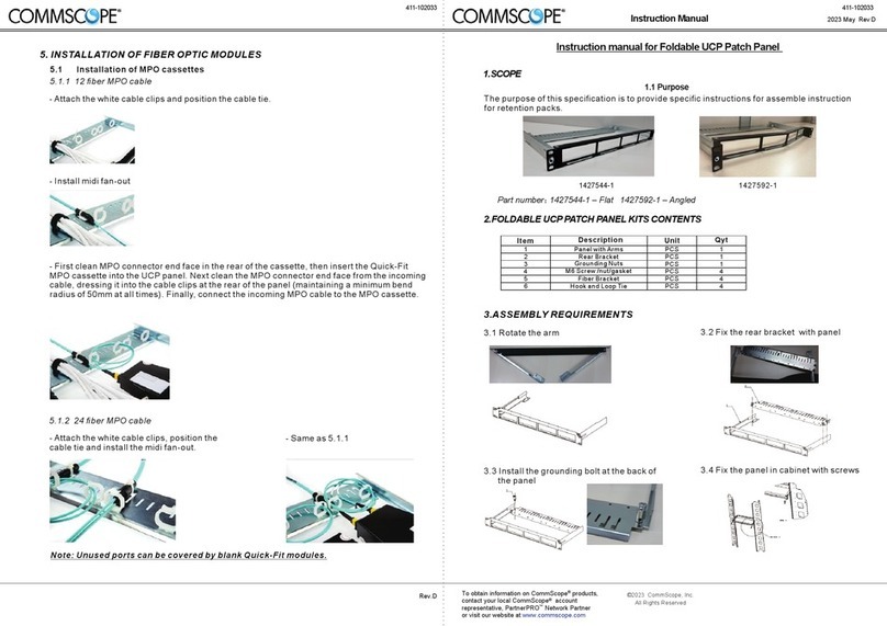
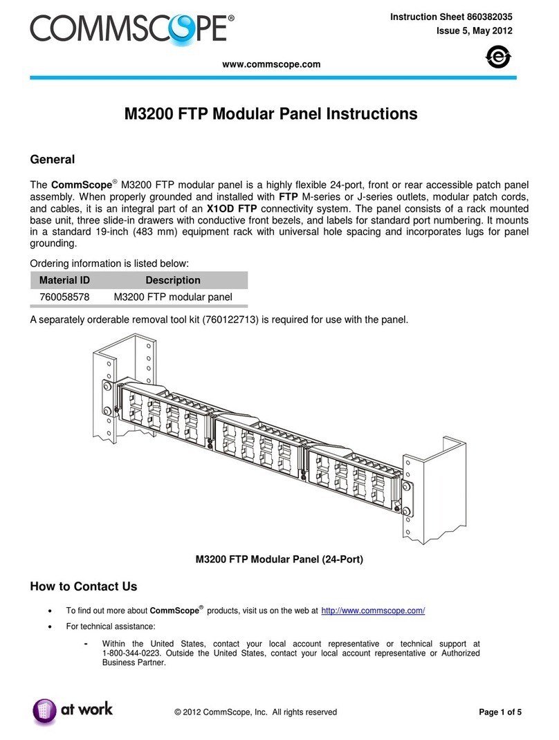
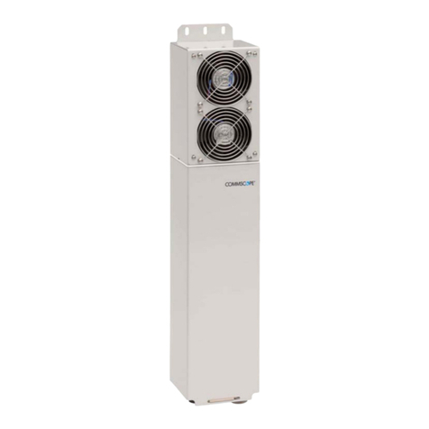
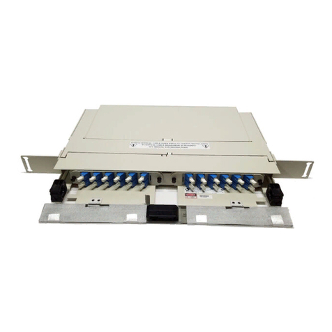
CommScope FPX Series User manual

CommScope

CommScope FPX Series User manual

CommScope ION-M23 SDARS User manual

CommScope

CommScope ION-M23 SDARS User manual

CommScope LSX User manual

CommScope

CommScope LSX User manual

CommScope MRJ21 Quick Fit Cassette User manual

CommScope

CommScope MRJ21 Quick Fit Cassette User manual

CommScope EHD User manual

CommScope

CommScope EHD User manual

CommScope SYSTIMAX 360 iPatch G2 MPO User manual

CommScope

CommScope SYSTIMAX 360 iPatch G2 MPO User manual

CommScope Uniprise Solutions HFTP-HD6B-1U-24 User manual

CommScope

CommScope Uniprise Solutions HFTP-HD6B-1U-24 User manual

CommScope ST-BSP60 User manual

CommScope

CommScope ST-BSP60 User manual

CommScope FPX Series User manual

CommScope

CommScope FPX Series User manual

CommScope ION-U EU H 23/23 User manual

CommScope

CommScope ION-U EU H 23/23 User manual

CommScope ION-M7P User manual

CommScope

CommScope ION-M7P User manual

CommScope RUCKUS SmartZone 300 User manual

CommScope

CommScope RUCKUS SmartZone 300 User manual

CommScope RUCKUS SmartZone 100 User manual
CommScope

CommScope RUCKUS SmartZone 100 User manual

CommScope TC-96370-IP User manual

CommScope

CommScope TC-96370-IP User manual

CommScope NG4access ODF Platform Value-Added Module User manual
CommScope

CommScope NG4access ODF Platform Value-Added Module User manual

CommScope Constellation CPT-PP-48C User manual

CommScope

CommScope Constellation CPT-PP-48C User manual

CommScope FPX Series User manual

CommScope

CommScope FPX Series User manual

CommScope SYSTIMAX 100BASE-T User manual

CommScope

CommScope SYSTIMAX 100BASE-T User manual

CommScope SD-4U-SPLICE PANEL User manual

CommScope

CommScope SD-4U-SPLICE PANEL User manual

CommScope NOVUX SEC 100 User manual

CommScope

CommScope NOVUX SEC 100 User manual

CommScope CPPR-QF-F-1U-E User manual

CommScope

CommScope CPPR-QF-F-1U-E User manual
CommScope Mini-OTE 300 User manual

CommScope

CommScope Mini-OTE 300 User manual

CommScope NG4access ODF Platform Value-Added Module User manual
CommScope

CommScope NG4access ODF Platform Value-Added Module User manual

CommScope FOSC-OC-6 User manual

CommScope

CommScope FOSC-OC-6 User manual

Popular Network Hardware manuals by other brands

D-Link DWL-3150 user manual

D-Link

D-Link DWL-3150 user manual

Cabletron Systems ELS10-26 reference guide

Cabletron Systems

Cabletron Systems ELS10-26 reference guide

ICP DAS USA WF-2572M user manual

ICP DAS USA

ICP DAS USA WF-2572M user manual

ENS ED9732H5NV-16P-A user manual

ENS

ENS ED9732H5NV-16P-A user manual

DivioTec SRA212N-004P4 user manual

DivioTec

DivioTec SRA212N-004P4 user manual

ZPE Nodegrid Gate SR quick start guide

ZPE

ZPE Nodegrid Gate SR quick start guide

Valcom VIP-814B manual

Valcom

Valcom VIP-814B manual

Axis C8110 installation guide

Axis

Axis C8110 installation guide

Rohde & Schwarz ENV4200 user manual

Rohde & Schwarz

Rohde & Schwarz ENV4200 user manual

Cyclades AlterPath ACS User, installation and servicing instructions

Cyclades

Cyclades AlterPath ACS User, installation and servicing instructions

Asus AAEON BOXER-8651AI user manual

Asus

Asus AAEON BOXER-8651AI user manual

Encore Networks BANDIT III quick start guide

Encore Networks

Encore Networks BANDIT III quick start guide

Inter-m AOE-212N Operation manual

Inter-m

Inter-m AOE-212N Operation manual

LG N2A2DD2 features and benefits

LG

LG N2A2DD2 features and benefits

Huawei RRU3908 V1 installation guide

Huawei

Huawei RRU3908 V1 installation guide

Paradyne Hotwire 8785 installation instructions

Paradyne

Paradyne Hotwire 8785 installation instructions

THOMSON 512320 manual

THOMSON

THOMSON 512320 manual

evertz 2400ODU instruction manual

evertz

evertz 2400ODU instruction manual

manuals.online logo
manuals.online logoBrands
  • About & Mission
  • Contact us
  • Privacy Policy
  • Terms and Conditions

Copyright 2025 Manuals.Online. All Rights Reserved.